PVGVICDSMDSR497Tablet PC
VIC LLC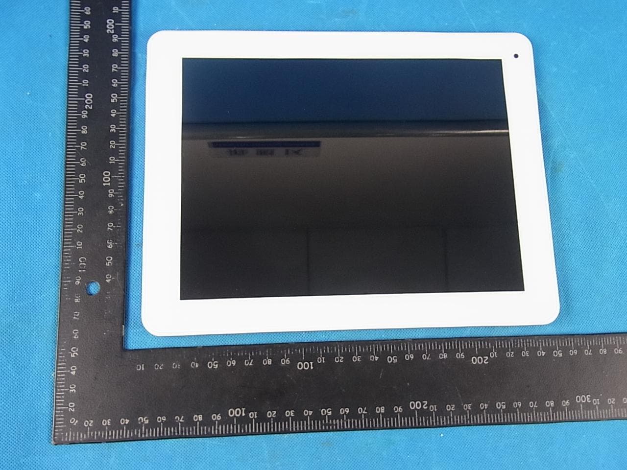
Click to zoom
Application Details
- Equipment Class
- DTS - Digital Transmission System
- Date of Grant
- Mar 18, 2013
- Application Purpose
- Original Equipment
- Date of Application
- Mar 18, 2013
- Equipment Note
- Tablet PC
- Frequency Range
- 2422.00000000 - 2452.00000000
- Company
- VIC LLC
- Country
- United States
Documents & Files
Document Text
Text extracted from the exhibit documents filed with the FCC. Open a document above to read the original.
Users Manual
1 Safety Precautions Do not subject the device to severe impact or drop it from heights. Do not use the device in extreme hot or cold, dusty or damp conditions. Do not expose it to direct sunlight. Avoid using the device near strong magnetic fields. Normal functioning of the product may be disturbed by ESD. If so, simply reset and restart the device. During file transmission, please handle with care and operate in a static-free environment. Keep the device away from water and other liquids. In the event that water or other liquids enter the device, power off the product immediately and clean the device. Do not use chemicals to clean the device in order to avoid corrosion. Clean it with a dry cloth. Do not install this equipment in a confined space such as a book case or similar unit. The ventilation should not be impeded by covering the ventilation openings with items such as newspaper, table-cloths, curtains etc. No naked flame sources, such as lighted candles, should be placed on the apparatus. Attention should be drawn to environmental aspects of battery disposal. Use the apparatus in moderate climates. We are not responsible for damage or lost data caused by malfunction, misuse, modification of the device or battery replacement. Do not attempt to disassemble, repair or modify the product. This will invalidate the warranty. If the device will not be used for an extended period of time, please charge the battery at least once per month to maintain battery life. Charge the battery if: a) The battery level icon displays (An empty battery) b) The device powers off automatically when restarted. c) There is no response when pressing keys with keys unlocked and battery full. Do not interrupt the connection when the device is being formatted or transferring files. Otherwise, data may be corrupted or lost. When the device is used as a portable HD, please use only per the instructions. Otherwise, permanent data loss could occur. Please use and install data using the attachments/accessories provided and only according to the manufacturer’s instruction. Please refer to the information on the bottom of the device for electrical and safety information before installing data or operating the device. To reduce the risk of fire or electric shock, do not expose this device to rain or moisture. The device should not be exposed to dripping or splashing. Never place objects filled with liquids, such as vases, on the device. There is danger of explosion if the battery is replaced incorrectly. Replace only with the same or equivalent type. 2 The battery (battery or batteries or battery pack) should not be exposed to excessive heat such as sunlight, fire or the like. Please follow responsible procedures for battery disposal. If the power adaptor disconnected from the device, the device will remain operable as long as the battery has sufficient charge. Listening Cautions This product respects the current regulations for limiting the output volume of consumer audio devices to a safe level. By listening to your device with headphones or earbuds at high volumes, you run the risk of permanent damage to your ears. Even if you get used to listening at high volumes and it seems normal to you, you still risk the possibility of damaging your hearing. Reduce the volume of your device to a reasonable level to avoid permanent hearing damage. If you hear ringing in your ears, reduce the volume or shut off your device. This device has been tested with the supplied earphones. In order to preserve your hearing, it is advised that you use only the following headphone models: the earphones supplied with your device, or any other headphones that respect the current regulations. Other types of headphones may produce higher volume levels.(At full power ,the prolonged listening of the walkman can damage the ear of the use) Do not use while operating a motorized vehicle. It may create a traffic hazard and is illegal in many areas. You should use extreme caution or temporarily discontinue use in potentially hazardous situations created by obstructed hearing. Even if your headphones or earphones are the open-air type designed to let you hear outside sounds, don’t turn up the volume so high that you can’t hear what’s around you. Sound can be deceiving. Over time your hearing “comfort level” adapts to higher volumes of sound. What sounds “normal” can actually be loud and harmful to your hearing. Guard against this by setting the volume of your device at a safe level BEFORE your hearing adapts. To establish a safe volume level: a. Start your volume control at a low setting. b. Slowly increase the sound until you can hear it comfortably and clearly, and without distortion. Once you have established a comfortable sound level, leave it there. This manual may not reflect your actual device’s operation. All information is subject to change without prior notification. Please follow your actual device’s operational procedures. 3 Table of Content Safety Precautions ................................................................................................... 1 Listening Cautions .................................................................................................... 2 Feature Summary .................................................................................................... 3 Accessories ............................................................................................................. 4 Buttons & Ports ........................................................................................................ 4 Charging Battery ...................................................................................................... 5 Transferring Files from Computer ............................................................................. 5 Turning On the Unit .................................................................................................…
Text truncated - open the document above for the full version.
Attestation Statements
Date:2013-2-27 FCC ID: PVGVICDSMDSR497 Subject: Ad Hoc Mode Function Declaration To Whom it may concern, This device is acting as slave and operating in the 2.4 GHz (2412 – 2462 MHz) band. Ad Hoc function is supported but not able to operate on non-US frequencies. Please contact the one signed below or the authorized agent for this filing. Thank you. Regards, Yours sincerely, Signatory Client’s signature Client’s name / title : Steve Siopsis / President Contact information / address : 106A West Summit Hill Drive,Knoxville,TN 37902, United States
Attestation Statements
Federal Communications Commission Authorization and Evaluation Division 1435 Oakland Mills Road Columbia, MD 21046 Date: 2013/2/27 SUBJECT: FCC Application for ( FCCID: PVGVICDSMDSR497) To Whom It May Concern: We, the undersigned, hereby attest to the fact that we will apply the Declaration of Conformity procedure to the class B computer peripheral portion of this composite device. We understand that devices subject to the DoC procedure are required to be tested to show compliance with the FCC technical regulations by a recognized accredited testing laboratory. The testing laboratory must be accredited by a Commission approved accreditation body or designated under the terms of a government-to-government Mutual Recognition Agreement (MRA). A listing of those accredited testing laboratories that have been recognized by the Commission is published on the FCC Webpage: https://apps.fcc.gov/oetcf/eas/reports/TestFirmSearch.cfm Select the "accredited" option to search for FCC recognized accredited test firms. Test facilities located in countries, where the U.S. does not have an operational Telcom MRA are not recognized by the FCC to test for the DoC procedure. Regards, Signatory Client’s signature Client’s name / title : Steve Siopsis / President Contact information / address : 106A West Summit Hill Drive,Knoxville,TN 37902, United States
Cover Letter(s)
SCS-F18: Project and Product Certification Representative Authorization Letter Page 1 of 2 Rev 3.0 775 Montague Expressway Milpitas, CA 95035 Tel: 408-526-1188 Fax: 408-526-1088 Email: [email protected] Project and Product Certification Representative Authorization Letter Reason for Amendment (current / obsolete) Revision History Approved Date From To Initial Release (obsolete) 1.0 1.0 Nov-14-2006 Revised wording (obsolete) 1.0 2.0 Sept–25-2007 Updated company template (current) 2.0 3.0 Jan-31-2012 SCS-F18: Project and Product Certification Representative Authorization Letter Page 2 of 2 Rev 3.0 2013/02/27 To: SIEMIC, INC. 775 Montague Expressway, Milpitas, CA 95035 USA Dear Sir/Madam, Re: Project and Product Certification Representative Authorization Letter We, _____ VIC LLC _____hereby authorize SIEMIC, INC. to act as a Certification Body for certifying for the following project(s): Product: Tablet PC Trade Name: N/A Model Name: VIC-DSM-DS-R497 FCC ID PVGVICDSMDSR497 We affirm that between SIEMIC and ___ VIC LLC ___, any difference in understanding, including test plan, measurement methods, applicable standards and relevant procedures and processes have been resolved prior to commencement of testing activities. Sincerely, Client’s signature Client’s name / title : Steve Siopsis / President Contact information / address : 106A West Summit Hill Drive,Knoxville,TN 37902, United States
Cover Letter(s)
SCS-F19: Confidentiality Request Letter Page 1 of 2 Rev 3.0 775 Montague Expressway Milpitas, CA 95035 Tel: 408-526-1188 Fax: 408-526-1088 Email: [email protected] Confidentiality Request Letter Reason for Amendment (current / obsolete) Revision History Approved Date From To Initial Release (obsolete) 1.0 1.0 Nov-14-2006 Adding CFR 2.459 (obsolete) 1.0 2.0 August – 11 - 2008 Updated company template & Added text box (current) 2.0 3.0 Jan-31-2012 SCS-F19: Confidentiality Request Letter Page 2 of 2 Rev 3.0 2013/02/27 To: Federal Communications Commission Authorization and Evaluation Division 7435 Oakland Mills Road Columbia, MD Subject: Permanent Confidentiality Request for FCC ID: PVGVICDSMDSR497 We hereby request confidential treatment of information accompanying this application as outlined below: - Block Diagram - Schematics - Operational Description The above materials contain trade secrets and proprietary information not customarily released to the public. The public disclosure of these materials may be harmful to the applicant and provide unjustified benefits to its competitors. The applicant understands that pursuant to Section 0.457 & 0.459 of the Rules, disclosure of this application and all accompanying documentation will not be made before the date of the Grant for this application. Sincerely, Client’s signature Client’s name / title : Steve Siopsis / President Contact information / address : 106A West Summit Hill Drive,Knoxville,TN 37902, United States
External Photos
APPENDIX-PHOTOGRAPHS OF EUT CONSTRUCTIONAL DETAILS Photo 1 Photo 2 Photo 3 Photo 4 Photo 5 Photo 6
Internal Photos
Photo 7 Photo 8 Photo 9 Photo 10 Photo 11 Photo 12 Photo 13 Photo 14 Photo 15 Photo 16
RF Exposure Info
RF EXPOSURE EVALUATION METHOD SAR Test Exclusion Thresholds for 100 MHz – 6 GHz and ≤ 50 mm Approximate SAR Test Exclusion Power Thresholds at Selected Frequencies and Test Separation Distances are illustrated in the following Table. Maximum measured transmitter power. 802.11B frequency range Maximum Conducted Output Power (dBm) Maximum Conducted Output Power (mW) 2412 9.45 8.81 2437 9.32 8.55 2462 9.12 8.17 802.11G frequency range Maximum Conducted Output Power (dBm) Maximum Conducted Output Power (mW) 2412 7.43 5.53 2437 7.25 5.31 2462 7.19 5.24 802.11N20 frequency range Maximum Conducted Output Power (dBm) Maximum Conducted Output Power (mW) 2412 7.01 5.02 2437 6.68 4.66 2462 6.54 4.51 802.11N40 frequency range Maximum Conducted Output Power (dBm) Maximum Conducted Output Power (mW) 2422 7.11 5.14 2437 6.61 4.58 2452 6.37 4.34 Refer to 447498 25 D01 General RF Exposure Guidance v05 Appendix A, you see that for Maximum Conducted Output Power 8.81 mW(<10mW), so no SAR is required.
Test Report
FCC RADIO TEST REPORT FCC ID: PVGVICDSMDSR497 Product: Tablet PC Trade Name: N/A Model Name: VIC-DSM-DS-R497 Serial Model: N/A Report No.: POCE13010731ORF Prepared for VIC LLC 106A West Summit Hill Drive,Knoxville,TN 37902,USA Prepared by Shenzhen POCE Technology Co., Ltd. Room 501-502, Bldg. 1, Xinghua Garden, Bao’an Road, Xixiang, Bao’an District, Shenzhen, Guangdong, China Tel: +86-755-29113252(30 lines)Fax: +86-755-29113135 Website: www. poce-cert.com Shenzhen POCE Technology Co., Ltd. Page 2 of 86 Report No.: POCE13010731ORF TEST RESULT CERTIFICATION Applicant’s name ................. : VIC LLC Address ................................. : 106A West Summit Hill Drive,Knoxville,TN 37902,USA Manufacture's Name ............ : VIC LLC Address ................................. : 106A West Summit Hill Drive,Knoxville,TN 37902,USA Product description Product name............................ : Tablet PC Model and/or type reference : VIC-DSM-DS-R497 Serial Model .............................. : N/A Standards ............................. : FCC Part15.247 Test procedure ............................... : ANSI C63.4-2003 This device described above has been tested by NTEK, and the test results show that the equipment under test (EUT) is in compliance with the FCC requirements. And it is applicable only to the tested sample identified in the report. This report shall not be reproduced except in full, without the written approval of NTEK, this document may be altered or revised by NTEK, personal only, and shall be noted in the revision of the document. Date of Test ........................................... : Date (s) of performance of tests ............. : 01 Mar. 2013 ~08 Mar. 2013 Date of Issue .......................................... : 09 Mar. 2013 Test Result.............................................. : Pass Testing Engineer : (Apple Huang) Technical Manager : (Tom Zhang) Authorized Signatory : (Bovey Yang) Shenzhen POCE Technology Co., Ltd. Page 3 of 86 Report No.: POCE13010731ORF Table of Contents Page 1 . SUMMARY OF TEST RESULTS 5 1.1 TEST FACILITY 6 1.2 MEASUREMENT UNCERTAINTY 6 2 . GENERAL INFORMATION 7 2.1 GENERAL DESCRIPTION OF EUT 7 2.2 DESCRIPTION OF TEST MODES 9 2.3 BLOCK DIGRAM SHOWING THE CONFIGURATION OF SYSTEM TESTED 10 2.4 DESCRIPTION OF SUPPORT UNITS(CONDUCTED MODE) 11 2.5 EQUIPMENTS LIST FOR ALL TEST ITEMS 12 3 . EMC EMISSION TEST 13 3.1 CONDUCTED EMISSION MEASUREMENT 13 3.1.1 POWER LINE CONDUCTED EMISSION LIMITS 13 3.1.2 TEST PROCEDURE 14 3.1.3 DEVIATION FROM TEST STANDARD 14 3.1.4 TEST SETUP 14 3.1.5 EUT OPERATING CONDITIONS 14 3.1.6 TEST RESULTS 15 3.2 RADIATED EMISSION MEASUREMENT 17 3.2.1 RADIATED EMISSION LIMITS 17 3.2.2 TEST PROCEDURE 18 3.2.3 DEVIATION FROM TEST STANDARD 18 3.2.4 TEST SETUP 19 3.2.5 EUT OPERATING CONDITIONS 20 3.2.6 TEST RESULTS (BETWEEN 9KHZ – 30 MHZ) 21 3.2.7 TEST RESULTS (BETWEEN 30MHZ – 1GHZ) 22 3.2.8 TEST RESULTS (ABOVE 1000 MHZ) 24 3.2.9 TEST RESULTS (RESTRICTED BANDS REQUIREMENTS) 48 4 . POWER SPECTRAL DENSITY TEST 64 4.1 APPLIED PROCEDURES / LIMIT 64 4.1.1 TEST PROCEDURE 64 4.1.2 DEVIATION FROM STANDARD 64 4.1.3 TEST SETUP 64 4.1.4 EUT OPERATION CONDITIONS 64 4.1.5 TEST RESULTS 65 5 . BANDWIDTH TEST 73 5.1 APPLIED PROCEDURES / LIMIT 73 5.1.1 TEST PROCEDURE 73 Shenzhen POCE Technology Co., Ltd. Page 4 of 86 Report No.: POCE13010731ORF Table of Contents Page 5.1.2 DEVIATION FROM STANDARD 73 5.1.3 TEST SETUP 73 5.1.4 EUT OPERATION CONDITIONS 73 5.1.5 TEST RESULTS 74 6 . PEAK OUTPUT POWER TEST 82 6.1 APPLIED PROCEDURES / LIMIT 82 6.1.1 TEST PROCEDURE 82 6.1.2 DEVIATION FROM STANDARD 82 6.1.3 TEST SETUP 82 6.1.4 EUT OPERATION CONDITIONS 82 6.1.5 TEST RESULTS 83 7 . ANTENNA REQUIREMENT 84 7.1 STANDARD REQUIREMENT 84 7.2 EUT ANTENNA 84 8 . EUT TEST PHOTO 85 APPENDIX-PHOTOGRAPHS OF EUT CONSTRUCTIONAL DETAILS Shenzhen POCE Technology Co., Ltd. Page 5 of 86 Report No.: POCE13010731ORF 1. SUMMARY OF TEST RESULTS Test procedures according to the technical standards: FCC Part15 (15.247) , Subpart C Standard Section Test Item Judgment Remark 15.207 Conducted Emission PASS 15.247 (a)(2) 6dB Bandwidth PASS 15.247 (b) Peak Output Power PASS 15.247 (c) Radiated Spurious Emission PASS 15.247 (d) Power Spectral Density PASS 15.205 Band Edge Emission PASS 15.203 Antenna Requirement PASS NOTE: (1)” N/A” denotes test is not applicable in this Test Report Shenzhen POCE Technology Co., Ltd. Page 6 of 86 Report No.: POCE13010731ORF 1.1 TEST FACILITY NTEK Testing Technology Co., Ltd Add.:1/F, Building E, Fenda Science Park, Sanwei Community, Xixiang Street, Bao’an District, Shenzhen P.R. China. FCC Registration No.:238937; IC Registration No.:9270A-1 CNAS Registration No.:L5516 1.2 MEASUREMENT UNCERTAINTY The reported uncertainty of measurement y ± U,where expended uncertainty U is based on a standard uncertainty multiplied by a coverage factor of k=2,providing a level of confidence of approximately 95 %。 No. Item Uncertainty 1 Conducted Emission Test ±1.38dB 2 RF power,conducted ±0.16dB 3 Spurious emissions,conducted ±0.21dB 4 All emissions,radiated(<1G) ±4.68dB 5 All emissions,radiated(>1G) ±4.89dB 6 Temperature ±0.5°C 7 Humidity ±2% Shenzhen POCE Technology Co., Ltd. Page 7 of 86 Report No.: POCE13010731ORF 2. GENERAL INFORMATION 2.1 GENERAL DESCRIPTION OF EUT Equipment Tablet PC Trade Name N/A Model Name VIC-DSM-DS-R497 Serial Model N/A Model Difference N/A Product Description The EUT is a Tablet PC Operation Frequency: 802.11b/g/n 20:2412~2462 MHz 802.11n 40: 2422~2452MHz Modulation Type: CCK/OFDM/DBPSK/DAPSK Bit Rate of Transmitter 802.11b:11/5.5/2/1 Mbps 802.11g:54/48/36/24/18/12/9/6Mbps 802.11n(20/40MHz):300/150/144.44/ 130/117/115.56/104/86.67/78/52/6.5 Mbps Number Of Channel 802.11b/g/n20: 11CH 802.11n 40: 7CH Antenna Designation: Please see Note 3. Output Power(Conducted): 802.11b: 9.45 dBm (Max.) 802.11g: 7.43 dBm (Max.) 802.11n: 7.11 dBm (Max.) Antenna Gain (dBi) 2 dbi Based on the application, features, or specification exhibited in User's Manual, the…
Text truncated - open the document above for the full version.
Test Setup Photos
Shenzhen POCE Technology Co., Ltd. Page 85 of 86 Report No.: POCE13010731ORF 8. EUT TEST PHOTO Radiated Measurement Photos Shenzhen POCE Technology Co., Ltd. Page 86 of 86 Report No.: POCE13010731ORF Conducted Measurement Photos
Contact Information
Applicant
Steve Siopsis(President)
Test Firm
Shenzhen NTEK Testing Technology Co., Ltd.Jason Chen
Technical Specifications
| # | Rule Parts | Frequency Range | Power Output |
|---|---|---|---|
| 2 | 15C | 2.42 GHz - 2.45 GHz | 5.14 mW |
Other Applications from VIC LLC
PVG320120903
Nov 05, 2012Tablet PC
Equipment Class
DXT - Part 15 Low Power Transceiver, Rx Verified