PWX-A75GSM 900/1800/1900 Mobile Phone
BenQ Mobile GmbH & Co. OHG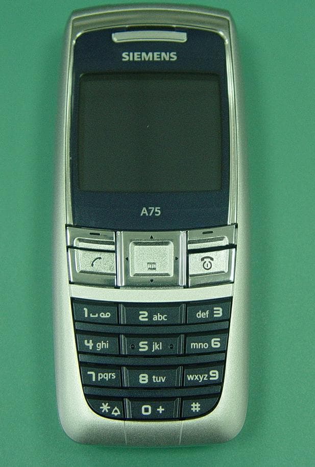
Click to zoom
Application Details
- Equipment Class
- PCE - PCS Licensed Transmitter held to ear
- Date of Grant
- Jun 05, 2005
- Application Purpose
- Original Equipment
- Date of Application
- Jun 05, 2005
- Equipment Note
- GSM 900/1800/1900 Mobile Phone
- Frequency Range
- 1850.20000000 - 1909.80000000
- Company
- BenQ Mobile GmbH & Co. OHG
- Country
- Germany
Documents & Files
Document Text
Text extracted from the exhibit documents filed with the FCC. Open a document above to read the original.
Users Manual
right page (1) of A75_Libra, fcc, us-en (30.05.2005, 10:36) © Siemens AG 2004, C:\Siemens\DTP-Satz\Produkte\A75_Libra_2\output\SUG\A75_Libra_FCC_us-en_050530_te_correction\Li- Contents 1 VAR Language: am; VAR issue date: 050324 Legal notices .............................. 2 Safety precautions ..................... 4 Overview of the phone .............. 9 Getting started ......................... 10 Switch on/off, PIN entry ........... 11 Security .................................... 11 Making a phone call ................. 12 Phonebook ............................... 13 Messages (SMS) ....................... 14 Setup ........................................ 15 Alarm clock .............................. 17 Ring tones ................................ 17 Surf & fun ................................. 18 Fast access key ......................... 18 Customer Care ......................... 19 Product data ............................. 20 Care and maintenance ............. 21 SAR (A75) ................................. 22 U.S. FDA ................................... 24 FCC/Industry Canada Notice .......................... 28 Ten Driving Safety Tips ............ 29 Intellectual property ................ 31 End user license agreement ................... 32 Contents © Siemens AG 2004, C:\Siemens\DTP-Satz\Produkte\A75_Libra_2\output\SUG\A75_Libra_FCC_us- left page (2) of A75_Libra, fcc, us-en, (30.05.2005, 10:36) Legal notices 2 VAR Language: am; VAR issue date: 050324 Legal notices The mobile phone described in this guide is approved for use on the GSM and GPRS net- works operating on the GSM 900, 1800 (DCS/PCN) and 1900 (PCS) bands. It is approved for use in the country where it was originally sold and may be approved for use in other countries. © 2005 Siemens Information and Communication Mobile, LLC. All rights reserved. Siemens and the A75 model phone are trademarks or registered trademarks of Siemens AG and/or its affiliates in the United States and/or other countries. T9® is a registered trademark of America Online, Inc. in the United States. Java and all Java-based trademarks and logos are trademarks or registered trademarks of Sun Microsystems, Inc. in the U.S and other countries. The names of actual companies and products mentioned herein may be the trademarks of their respective owners. Disclaimer The information contained in the User Guide is written for the A75 phone. Siemens reserves the right to make changes and improvements to the products and any of the features of the products described in this document without prior notice. The contents of the user guide are provided "AS IS". Except as required by applicable law, no warranties of any kind, either express or im- plied, including, but not limited to, the im- plied warranties of merchantability and fit- ness for a particular purpose, are made in relation to the accuracy, reliability or con- tents of this document. Siemens reserves the right to revise the user guide or with- draw it at any time without prior notice. Un- der no circumstances shall Siemens be re- sponsible for any loss of data or income or any special, incidental, consequential or in- direct damages howsoever caused. Export Information The mobile phone may be subject to export regulation of the United States and other countries. Diversion contrary to law is pro- hibited. You must comply with all applica- ble export laws, restrictions and regulations of the United States foreign agencies or au- thorities, and may not export, or transfer for the purpose of re-export, the mobile phone or any part of the phone in violation of any applicable restrictions, laws or regu- lations, or without all necessary approvals. Network Services A number of features included in this guide are called Network Services. They are special services provided by wireless service providers. In order to use any of these Network Services, you must sub- scribe to these service(s) from your ser- vice provider and obtain instructions for their use. Some of these Network Servic- es may not be available when roaming on a network other than your home network. Standby and Talk Time Information The mobile phone incorporates features that are new to the mobile phone world. These may include color displays and lighting, graphic games, music reproduc- tion and browsing the Internet. The way you use the display and the features will affect the performance of the battery and how long it lasts between charge cycles. The quoted standby times and talk times show the minimum and maximum per- formance that can be expected from the right page (3) of A75_Libra, fcc, us-en, (30.05.2005, 10:36) © Siemens AG 2004, C:\Siemens\DTP-Satz\Produkte\A75_Libra_2\output\SUG\A75_Libra_FCC_us- 3 Legal notices VAR Language: am; VAR issue date: 050324 battery under normal network conditions and with the default settings as set by the factory. However, playing games (particu- larly with the backlight continuously switched on) and listening to music will shorten the time available for standby and to make and receive telephone calls. Operation times also vary depending on network conditions, SIM settings, charg- ing and battery condition, how you use your phone and other factors. Memory The mobile phone contains an internal memory device that stores the software required to operate the mobile phone, communicate with the GSM/GPRS net- work and provide the user interface. Some features in the internal memory run additional devices and some addition- al games and utilities. The amount of memory available in the mobile phone is finite and may be insufficient to store large numbers of applications and files. Warning! Remember to back up your data and to do so fre- quently. Always back up all data and programs before sending the mobile phone in for repair. © Siemens AG 2004, C:\Siemens\DTP-Satz\Produkte\A75_Libra_2\output\SUG\A75_Libra_FCC_us- left page (4) of A75_Libra, fcc, us-en, (30.05.2005, 10:36) Safety precautions 4 VAR Language: am; VAR i…
Text truncated - open the document above for the full version.
Cover Letter(s)
Siemens Communications, Inc. Siemens Communications, Inc. 16745 West Bernardo Drive Suite 120 San Diego, CA 92127 Tel. 858-521-3200 Federal Communication Commission Equipment Authorization Division, Application Processing Branch 7435 Oakland Mills Road Columbia, MD 21048 May 7, 2005 TO WHOM IT MAY CONCERN Pursuant to Paragraphs §0.457 and 0.459 of the Commission’s Rules (47 C.F.R.) and Section §552(b)(4) of the Freedom of Information Act, Siemens Communications, Inc requests confidentiality for the following products: FCC ID Number Product Title/Model PWX – A75 Tri -Band/A75 For the product stated above, we request that the following information be held confidential: 1) Electrical Schematics of the Circuitry 2) Block Diagram 3) Parts List 4) Technical Description Required for section 2.1003 (c) • Operational Description 5) Tune-up Procedure No other items submitted as part of the equipment authorization filing process are deemed confidential. The above exhibits contain Siemens Communications, Inc trade secrets and proprietary information that could be of benefit to our competitors regarding the design of our mobile handset. This material is not customarily available to the general public and we request that it be withheld from public inspection. If you have any questions, please feel free to contact me at the address shown below. Sincerely, Kevin Wolentarski Regulatory Engineer
External Photos
Confidential Page 1 of3 A75 Front View Confidential Page 2 of3 AF75 RearView Confidential Page 3 of3 A75 Side View
ID Label/Location Info
Date 22.04.2005 Approval label 3 13.05.05 WQ Name WangQi A75/IMEI/Z85/ STD 2 23.04.05 WQ MD PD LPD BJ Z30880-Z9999-Z85-* 1 22.04.05 WQ LETTERING PLAN Version Date Token SIEMENS AG DIS 100990 Page 1 From 1 A24850-V1-A4-2 VORSTD.DOC White label with black lettering SIEMENS S30880-SXXXX-XXXX-1 YY XXXXXXXX SSSSSS C 0682 Typ-Approval Code: TAC Made xx Xxxxxxx 3) A75 Barcode: Typ 128, table C and B Characteristic: IMEI-No. has 15 digits Digit 1-14 is generated as Barcode with table C . Digit 15 is printed with table B. 1) 2) 4) 5) 6) 7) 8) Current serial number (6 digits) Assigned by PICS Final-Assembly Code: FAC 15. digit CHECK DIGIT 10) 10) 10) 11)12) F C C ID : P W X -A 7 5 IC :267E -A75 13) Ink ribbon: TTR-Band Ricoh 110-A Font: Title blocks concentric 1) Corporate logo: 1.5 SN 66324 2) Product name: Internal font D, size 4 3) Made xx Xxxxxxx Internal font B, size 3 / Depending on production location 4) Code of date: Internal font D, size 4 e.g. F3 March └─1995 5) Code number: Internal font D, size 3 6) CE- identification: Height: 5 mm 7) Barcode IMEI-No.: Code: 128 Size: 2 Ratio: 3.0 Height: 3 mm 8) IMEI-No. (plain writing): Internal font D, size 4, space between TAC, FAC, serial no. and 15.digit 10) Document for IMEI-No. allocation: DIS xxxxx Valid is the highest level in the system 11) Code number: Corresponding to the number of the transceiver unit part list 12) “Made in Germany“ For production in Germany “Made in Xxxxxxx“ For production out of Germany – for details please see lettering plan of retail box label 13) Canada IC and US FCC font: B3 Date 22.04.2005 Approval label 3 13.05.05 WQ Name WangQi A75/IMEI/Z85/ STD 2 23.04.05 WQ MD PD LPD BJ Z30880-Z9999-Z85-* 1 22.04.05 WQ LETTERING PLAN Version Date Token SIEMENS AG DIS 100990 Page 2 From 1 A24850-V1-A4-2 VORSTD.DOC
Internal Photos
Confidential Page 1 of4 A75 Open Battery Cover Confidential Page 2 of4 A75Disassembly Step 1 Confidential Page 3 of4 CF75Disassembly Step 2 Confidential Page 4 of4 CF75Disassembly Step 3
RF Exposure Info
DAT-P-152/98-01 SAR Report, Siemens_6620_483_FCC_1900_Caldata_A75 Appendix for the Report Dosimetric Assessment of the Siemens A75 (FCC ID: PWX-A75) According to the FCC Requirements Calibration Data March 22, 2005 IMST GmbH Carl-Friedrich-Gauß-Str. 2 D-47475 Kamp-Lintfort Customer Siemens Information & Communication Mobile LLC 16475 West Bernado Dirve, Suite 400 CA 92127 San Diego The test results only relate to the items tested. This report shall not be reproduced except in full without the written approval of the testing laboratory.
RF Exposure Info
DAT-P-152/98-01 SAR Report, Siemens_6620_483_FCC_1900_SAR Plots_A75 Page 1 of 11 Appendix for the Report Dosimetric Assessment of the Siemens A75 (FCC ID: PWX-A75) According to the FCC Requirements SAR Distribution Plots March 18, 2005 IMST GmbH Carl-Friedrich-Gauß-Str. 2 D-47475 Kamp-Lintfort Customer Siemens Information & Communication Mobile LLC 16475 West Bernado Drive, Suite 400 CA 92127 San Diego The test results only relate to the items tested. This report shall not be reproduced except in full without the written approval of the testing laboratory. dasy_report_fcc_1900_plots_1.0.doc/05.01.2005/ABo SAR Report, Siemens_6620_483_FCC_1900_SAR Plots_A75 Page 2 of 11 dasy_report_fcc_1900_plots_1.0.doc/05.01.2005/ABo Table of Contents 1 SAR DISTRIBUTION PLOTS, PCS 1900 HEAD....................................................................................... 3 2 SAR DISTRIBUTION PLOTS, PCS 1900 BODY WITH HEADSET IN GSM MODE............................ 7 3 SAR DISTRIBUTION PLOTS, PCS 1900 BODY WITH DATA CABLE, GPRS CLASS 8................. 9 4 SAR Z-AXIS SCANS (VALIDATION)......................................................................................................... 10 5 SAR Z-AXIS SCANS (MEASUREMENTS)................................................................................................ 11 SAR Report, Siemens_6620_483_FCC_1900_SAR Plots_A75 Page 3 of 11 dasy_report_fcc_1900_plots_1.0.doc/05.01.2005/ABo 1 SAR Distribution Plots, PCS 1900 head Test Laboratory: IMST GmbH, DASY Blue (I); File Name: 125bplm_1.da4 DUT: Siemens; Type: A75; Serial: 004400000061125 Program Name: Cheek Left Communication System: GSM 1900; Frequency: 1880 MHz;Duty Cycle: 1:8.3 Medium parameters used: σ = 1.4 mho/m, ε r = 38.4; ρ = 1000 kg/m 3 Phantom section: Left Section DASY4 Configuration: - Probe: ET3DV6R - SN1669; ConvF(5.11, 5.11, 5.11); Calibrated: 13.01.2005 - Sensor-Surface: 4mm (Mechanical Surface Detection) - Electronics: DAE3 Sn489; Calibrated: 03.09.2004 - Phantom: SAM Glycol 1176; Type: Speag; Serial: 1176 - Measurement SW: DASY4, V4.5 Build 19; Postprocessing SW: SEMCAD, V1.8 Build 146 Cheek Left/Area Scan (6x10x1): Measurement grid: dx=15mm, dy=15mm Maximum value of SAR (measured) = 0.307 mW/g Cheek Left/Zoom Scan (7x7x7)/Cube 0: Measurement grid: dx=5mm, dy=5mm, dz=5mm Reference Value = 14.5 V/m; Power Drift = 0.028 dB Peak SAR (extrapolated) = 0.461 W/kg SAR(1 g) = 0.278 mW/g; SAR(10 g) = 0.156 mW/g Maximum value of SAR (measured) = 0.314 mW/g Cheek Left/Zoom Scan (7x7x7)/Cube 1: Measurement grid: dx=5mm, dy=5mm, dz=5mm Reference Value = 14.5 V/m; Power Drift = 0.028 dB Peak SAR (extrapolated) = 0.334 W/kg SAR(1 g) = 0.194 mW/g; SAR(10 g) = 0.109 mW/g Maximum value of SAR (measured) = 0.212 mW/g Fig. 1: SAR distribution for PCS 1900, channel 661, cheek position, left side of head (16.03.2005; Ambient Temperature: 21.6° C; Liquid Temperature: 20.5° C). SAR Report, Siemens_6620_483_FCC_1900_SAR Plots_A75 Page 4 of 11 dasy_report_fcc_1900_plots_1.0.doc/05.01.2005/ABo Test Laboratory: IMST GmbH, DASY Blue (I); File Name: 125bplm_2.da4 DUT: Siemens; Type: A75; Serial: 004400000061125 Program Name: Tilted Left Communication System: GSM 1900; Frequency: 1880 MHz;Duty Cycle: 1:8.3 Medium parameters used: σ = 1.4 mho/m, ε r = 38.4; ρ = 1000 kg/m 3 Phantom section: Left Section DASY4 Configuration: - Probe: ET3DV6R - SN1669; ConvF(5.11, 5.11, 5.11); Calibrated: 13.01.2005 - Sensor-Surface: 4mm (Mechanical Surface Detection) - Electronics: DAE3 Sn489; Calibrated: 03.09.2004 - Phantom: SAM Glycol 1176; Type: Speag; Serial: 1176 - Measurement SW: DASY4, V4.5 Build 19; Postprocessing SW: SEMCAD, V1.8 Build 146 Tilted Left/Area Scan (6x10x1): Measurement grid: dx=15mm, dy=15mm Maximum value of SAR (measured) = 0.352 mW/g Tilted Left/Zoom Scan (7x7x7)/Cube 0: Measurement grid: dx=5mm, dy=5mm, dz=5mm Reference Value = 15.9 V/m; Power Drift = -0.084 dB Peak SAR (extrapolated) = 0.516 W/kg SAR(1 g) = 0.314 mW/g; SAR(10 g) = 0.174 mW/g Maximum value of SAR (measured) = 0.349 mW/g Fig. 2: SAR distribution for PCS 1900, channel 661, tilted position, left side of head (16.03.2005; Ambient Temperature: 21.6° C; Liquid Temperature : 20.4° C). SAR Report, Siemens_6620_483_FCC_1900_SAR Plots_A75 Page 5 of 11 dasy_report_fcc_1900_plots_1.0.doc/05.01.2005/ABo Test Laboratory: IMST GmbH, DASY Blue (I); File Name: 125bprm_1.da4 DUT: Siemens; Type: A75; Serial: 004400000061125 Program Name: Cheek Right Communication System: GSM 1900; Frequency: 1880 MHz;Duty Cycle: 1:8.3 Medium parameters used: σ = 1.4 mho/m, ε r = 38.4; ρ = 1000 kg/m 3 Phantom section: Right Section DASY4 Configuration: - Probe: ET3DV6R - SN1669; ConvF(5.11, 5.11, 5.11); Calibrated: 13.01.2005 - Sensor-Surface: 4mm (Mechanical Surface Detection) - Electronics: DAE3 Sn489; Calibrated: 03.09.2004 - Phantom: SAM Glycol 1176; Type: Speag; Serial: 1176 - Measurement SW: DASY4, V4.5 Build 19; Postprocessing SW: SEMCAD, V1.8 Build 146 Cheek Right/Area Scan (6x10x1): Measurement grid: dx=15mm, dy=15mm Maximum value of SAR (measured) = 0.459 mW/g Cheek Right/Zoom Scan (7x7x7)/Cube 0: Measurement grid: dx=5mm, dy=5mm, dz=5mm Reference Value = 12.3 V/m; Power Drift = -0.149 dB Peak SAR (extrapolated) = 0.800 W/kg SAR(1 g) = 0.442 mW/g; SAR(10 g) = 0.236 mW/g Maximum value of SAR (measured) = 0.504 mW/g Fig. 3: SAR distribution for PCS 1900, channel 661, cheek position, right side of head (16.03.2005; Ambient Temperature: 21.6° C; Liquid Temperature : 20.4° C). SAR Report, Siemens_6620_483_FCC_1900_SAR Plots_A75 Page 6 of 11 dasy_report_fcc_1900_plots_1.0.doc/05.01.2005/ABo Test Laboratory: IMST GmbH, DASY Blue (I); File Name: 125bprm_2.da4 DUT: Siemens; Type: A75; Serial: 004400000061125 Program Name: Tilted Right Communication System: GSM 1900; Frequency: 1880 MHz;Duty Cycle: 1:8.3 Medium parameters used: σ = 1.4 mho/m, ε r = 38.4; ρ = 1000 kg/m 3 Phantom section: Right Section DASY4 Configuration: - Probe: ET3DV6R - SN1669; ConvF(5.11, 5.11, 5.11); …
Text truncated - open the document above for the full version.
RF Exposure Info
DAT-P-152/98-01 SAR Report, Siemens_6620_483_FCC_1900_A75 Page 1 of 33 Report Dosimetric Assessment of the Portable Device Siemens A75 (FCC ID: PWX-A75) According to the FCC Requirements March 18, 2005 IMST GmbH Carl-Friedrich-Gauß-Str. 2 D-47475 Kamp-Lintfort Customer Siemens Information & Communication Mobile LLC 16475 West Bernado Drive, Suite 400 CA 92127 San Diego The test results only relate to the items tested. This report shall not be reproduced except in full without the written approval of the testing laboratory. dasy_repo r t_fcc_1900_4.1.doc/07.01..2005/CH SAR Report, Siemens_6620_483_FCC_1900_A75 Page 2 of 33 dasy_report_fcc_1900_4.1.doc/07.01..2005/CH Executive Summary The A75 is a mobile phone (Portable Device) from Siemens operating in the 900 MHz, 1800 MHz and 1900 MHz frequency range. The device has an integrated antenna and the system concepts used are the GSM 900, GSM 1800 and PCS 1900 standards including GPRS Class 8 capability. The objective of the measurements done by IMST was the dosimetric assessment of one device in the PCS 1900 standard. The examinations have been carried out with the dosimetric assessment system ÑDASY4ì. The measurements were made according to the Supplement C to OET Bulletin 65 of the Federal Communications Commission (FCC) Guidelines [OET 65] for evaluating compliance of mobile and portable devices with FCC limits for human exposure (general population) to radiofrequency emissions. All measurements have been performed in accordance to the recommendations given by SPEAG. The Siemens A75 mobile phone (FCC ID: PWX-A75) is in compliance with the Federal Communications Commission (FCC) Guidelines [OET 65] for uncontrolled exposure. The phone was tested in addition to the head positions in the following configurations: Body worn: • GSM with headset and FCT 650 carry case (10 mm distance) • GSM with headset and FCL 600 carry case (13 mm distance) • GPRS (Class 8) with data cable and FCL 600 carry case (13 mm distance) prepared by: ........................................... reviewed by: ..................................... AndrÈ van den Bosch Dipl.- Ing. Christoph Hennes test engineer quality assurance engineer IMST GmbH Carl-Friedrich-Gaufl-Strafle 2 D-47475 Kamp-Lintfort Tel. +49- 2842-981 373 Fax +49- 2842-981 399 email: [email protected] SAR Report, Siemens_6620_483_FCC_1900_A75 Page 3 of 33 dasy_report_fcc_1900_4.1.doc/07.01..2005/CH Table of Contents 1 SUBJECT OF INVESTIGATION.................................................................................................................... 4 2 THE IEEE STANDARD C95.1 AND THE FCC EXPOSURE CRITERIA................................................. 4 2.1 DISTINCTION BETWEEN EXPOSED POPULATION, DURATION OF EXPOSURE AND FREQUENCIES........... 4 2.2 DISTINCTION BETWEEN MAXIMUM PERMISSIBLE EXPOSURE AND SAR LIMITS....................................... 5 2.3 SAR LIMIT.................................................................................................................................................. 5 3 THE FCC MEASUREMENT PROCEDURE................................................................................................. 6 3.1 GENERAL REQUIREMENTS......................................................................................................................... 6 3.2 DEVICE OPERATING NEXT TO A PERSON’S EAR....................................................................................... 6 4 BODY-WORN CONFIGURATIONS.............................................................................................................. 9 4.1 POC (PTT) POSITION...............................................................................................................................9 4.2 PHANTOM REQUIREMENTS...................................................................................................................... 10 4.3 TEST TO BE PERFORMED......................................................................................................................... 10 5 THE MEASUREMENT SYSTEM................................................................................................................. 10 5.1 PHANTOM................................................................................................................................................. 12 5.2 PROBE...................................................................................................................................................... 12 5.3 MEASUREMENT PROCEDURE.................................................................................................................. 13 5.4 UNCERTAINTY ASSESSMENT................................................................................................................... 14 6 SAR RESULTS............................................................................................................................................... 15 7 EVALUATION................................................................................................................................................. 17 8 APPENDIX....................................................................................................................................................... 19 8.1 ADMINISTRATIVE DATA............................................................................................................................ 19 8.2 DEVICE UNDER TEST AND TEST CONDITIONS......................................................................................... 19 8.3 TISSUE RECIPES...................................................................................................................................... 20 8.4 MATERIAL PARAMETERS......................................................................................................................... 20 8.5 SIMPLIFIED PERFORMANCE CHECKING.......................................................................................…
Text truncated - open the document above for the full version.
Test Report
Siemens Communications, Inc. Project: A75 Date: 21-04-2005 Test case: Cond. Power Page: 2 of 6 ________________________________________________________________________________ Siemens Communications, Inc. - 2 - Report No: A75_conducted_power.doc Contents 1 Objective and Method ..............................................................................3 2 Results.......................................................................................................3 2.1 GSM 900..................................................................Error! Bookmark not defined. 2.2 GSM 1800................................................................Error! Bookmark not defined. 2.3 GSM 1900................................................................................................................ 3 3 Minutes of Test .........................................................................................4 3.1 Description of device under test.................................................................................. 4 3.2 Measurement Set-up................................................................................................. 4 4 Calibration Certificate ..............................................................................6 Siemens Communications, Inc. Project: A75 Date: 21-04-2005 Test case: Cond. Power Page: 3 of 6 ________________________________________________________________________________ Siemens Communications, Inc. - 3 - Report No: A75_conducted_power.doc 1 Objective and Method FCC approval for mobile phones requires reporting output power at RF output terminal pursuant to title 47 CFR part 2.1046. SIEMENS devices use special test fixtures with 50 Ohm connection suitable for such measurements. Using a special adapter and connecting the phone to an appropriate load in terms of the input port of the measurement equipment used, we hereby report the values for highest power setting. 2 Results 2.1 GSM 1900 Average Power during burst at connector Device IMEI Number Ch. 512 1850.2 MHz Ch. 661 1880.0 MHz Ch. 810 1909.8 MHz 004400000097517 29.0 29.1 29.1 004400000097335 29.1 29.2 29.2 004400000097384 29.1 29.2 29.2 004400000097467 29.0 29.1 29.1 004400000097442 29.0 29.1 29.1 004400000097293 29.0 29.1 29.1 004400000061125 29.0 29.1 29.1 Table 2.1 Results of power measurements at connector in the GSM 1900 Band Siemens Communications, Inc. Project: A75 Date: 21-04-2005 Test case: Cond. Power Page: 4 of 6 ________________________________________________________________________________ Siemens Communications, Inc. - 4 - Report No: A75_conducted_power.doc 3 Minutes of Test 3.1 Description of device under test Mobile Phone: Siemens A75 Frequency Range GSM 900: 880 – 915 MHz Frequency Range GSM 1800: 1710 – 1785 MHz Frequency Range GSM 1900: 1850 – 1990 MHz Siemens Part Number: S30880-Q2790-****-* 3.2 Measurement Set-up Base Station Simulator: CMU 200 Serial Number: 106697 Software Version: Base 3.54 / GSM 3.55 Figure 1: Block Diagram of set-up for conducted power measurement Base Station Simulator DUT Special Adapter Siemens Communications, Inc. Project: A75 Date: 21-04-2005 Test case: Cond. Power Page: 5 of 6 ________________________________________________________________________________ Siemens Communications, Inc. - 5 - Report No: A75_conducted_power.doc Figure 2: Set-up for conducted power measurement Siemens Communications, Inc. Project: A75 Date: 21-04-2005 Test case: Cond. Power Page: 6 of 6 ________________________________________________________________________________ Siemens Communications, Inc. - 6 - Report No: A75_conducted_power.doc 4 Calibration Certificate
Test Report
TTI-P-G 081/94-A0 Accredited according to ISO/IEC 17025 Bluetooth Qualification Test Facility (BQTF) FCC listed # 101450 IC recognized # 3925 CETECOM Inc. 411 Dixon Landing Road Milpitas, CA 95035 U.S.A. Phone: + 1 (408) 586 6200 Fax: + 1 (408) 586 6299 E-mail: [email protected] http://www.cetecom.com CETECOM Inc. is a Delaware Corporation with Corporation number: 2113686 Board of Directors: Dr. Harald Ansorge, Dr. Klaus Matkey, Hans Peter May V1.1 2003-03-01 The BLUETOOTH trademarks are owned by Bluetooth SIG, Inc., U.S.A. and licensed to CETECOM Inc. © Copyright by CETECOM FCC Test report Test report no.: EMC_916FCC-24_2005_A75 FCC Part 24 / RSS 133 FCC ID: PWX-A75 IC ID: 267E-A75 CETECOM Inc. Test report no.: EMC_916FCC-24_2005_A75 Issue date: 2005-06-01 Page 2 (51) Table of Contents 1 General information 1.1 Notes 1.2 Testing laboratory 1.3 Details of applicant 1.4 Application details 1.5 Test item 1.6 Test standards 2 Technical test 2.1 Summary of test results 2.2 Test report 1 General information 1.1 Notes The test results of this test report relate exclusively to the test item specified in 1.5. The CETECOM Inc. does not assume responsibility for any conclusions and generalisations drawn from the test results with regard to other specimens or samples of the type of the equipment represented by the test item. The test report may only be reproduced or published in full. Reproduction or publication of extracts from the report requires the prior written approval of the CETECOM Inc. TEST REPORT PREPARED BY: EMC Engineer: Harpreet Sidhu 1.2 Testing laboratory CETECOM Inc. 411 Dixon Landing Road, Milpitas, CA-95035, USA Phone: +1 408 586 6200 Fax: +1 408 586 6299 E-mail: [email protected] Internet: www.cetecom.com CETECOM Inc. Test report no.: EMC_916FCC-24_2005_A75 Issue date: 2005-06-01 Page 3 (51) 1.3 Details of applicant Name : SIEMENS ICM Street : 16745 West Bernardo Drive City / Zip Code : San Diego CA 92127 Country : U.S.A Contact : Kevin Wolentarski Telephone : +1 858-521-3352 Tele-fax : +1 858-521-3105 e-mail : [email protected] 1.4 Application details Date of receipt test item : 2005-05-04 Date of test : 2005-04-04/11/25 1.5 Test item Manufacturer : SIEMENS Street Address : Suedstr. 9 City / Zip Code : 47475 Kamp-Lintfort Country : Germany Marketing Name : A75 Model No. : A75 Description : GSM 1900 Mobile Phone FCC-ID : PWX-A75 IC ID : 267E-A75 Additional information Test Sample for GSM : IMEI: 00-4400-00-009746-7 Frequency : 1850.2MHz – 1909.8MHz for PCS 1900 Type of modulation : GMSK Number of channels : 299 for PCS 1900 Antenna : External Power supply : Battery or Charger (AC Adaptor) Output power : 31.70dBm (1.48W) max. EIRP measured for PCS 1900 Extreme vol. Limits : 3.6VDC to 4.5VDC (nominal: 3.7VDC) Extreme temp. Tolerance : -30°C to +50°C 1.6 Test standards FCC Part 24 / RSS133 r1 CETECOM Inc. Test report no.: EMC_916FCC-24_2005_A75 Issue date: 2005-06-01 Page 4 (51) 2 Technical test 2.1 Summary of test results No deviations from the technical specification(s) were ascertained in the course of the tests Performed Final Verdict: (only “passed” if all single measurements are “passed”) Passed Technical responsibility for area of testing: 2005-06-01 EMC & Radio Pete Krebill (EMC Engineer) Date Section Name Signature Responsible for test report and project leader: 2005-06-01 EMC & Radio Harpreet Sidhu (EMC Engineer) Date Section Name Signature CETECOM Inc. Test report no.: EMC_916FCC-24_2005_A75 Issue date: 2005-06-01 Page 5 (51) 2.2 Test report TEST REPORT Test report no.: EMC_916FCC-24_2005_A75 CETECOM Inc. Test report no.: EMC_916FCC-24_2005_A75 Issue date: 2005-06-01 Page 6 (51) TEST REPORT REFERENCE PARAMETER TO BE MEASURED PARAGRAPH PAGE POWER OUTPUT § 24.232(b) 7 FREQUENCY STABILITY § 2.1055 / § 24.235 10 OCCUPIED BANDWIDTH §2.1049(h)(i) 12 EMISSION BANDWIDTH §24.238(b) 16 EMISSIONS LIMITS §24.238 20 BAND EDGE COMPLIANCE §24.238(b) 35 RECEIVER RADIATED EMISSIONS § 15.209 37 CONDUCTED SPURIOUS EMISSIONS 43 CONDUCTED EMISSIONS § 15.107/207 47 TEST EQUIPMENT AND ANCILLARIES USED FOR TESTS 49 BLOCK DIAGRAMS 50 CETECOM Inc. Test report no.: EMC_916FCC-24_2005_A75 Issue date: 2005-06-01 Page 7 (51) POWER OUTPUT § 24.232(b) Summary: During the process of testing, the E…
Text truncated - open the document above for the full version.
Contact Information
Applicant
Dr. Martin Weinberger(Engineering Manager)
Test Firm
Cetecom Inc.Lothar Schmidt
Technical Specifications
| # | Rule Parts | Frequency Range | Power Output | Emission | Tolerance |
|---|---|---|---|---|---|
| 1 | 24E | 1.85 GHz - 1.91 GHz | 1.48 W | 300KGXW | 0.0244000000 ppm |
Other Applications from BenQ Mobile GmbH & Co. OHG
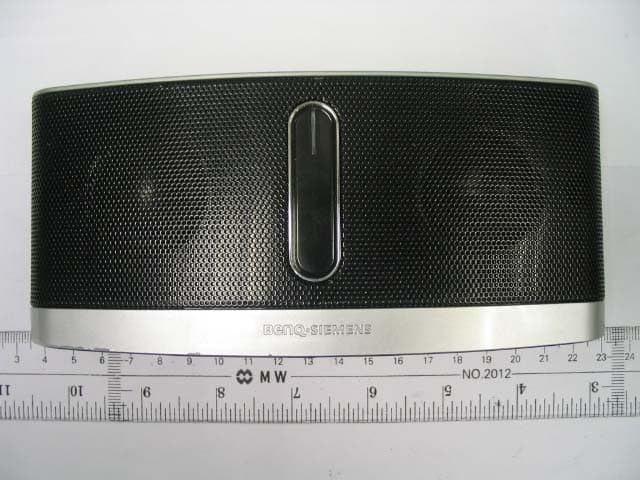
PWX-IMS100
Nov 09, 2006Mobile Sound Set Bluetooth
Equipment Class
DSS - Part 15 Spread Spectrum Transmitter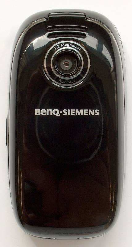
PWX-SL91
Sep 13, 2006GSM 900/1800/1900, UMTS Mobile Phone with BT
Equipment Class
PCE - PCS Licensed Transmitter held to ear
PWX-HKW100
Aug 30, 2006HKW-100 CK Bluetooth Easy
Equipment Class
DSS - Part 15 Spread Spectrum Transmitter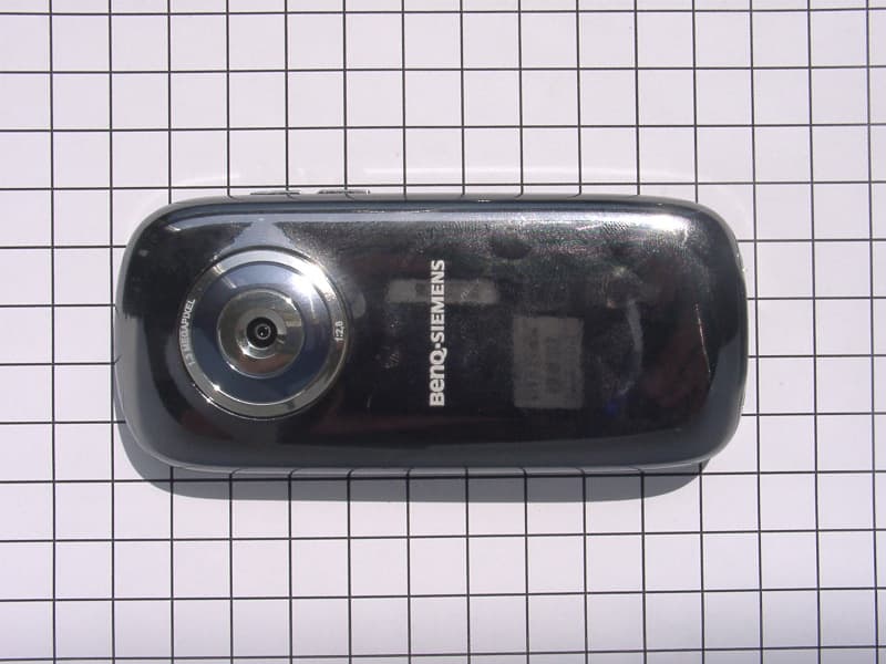
PWX-E71A
Aug 09, 2006GSM 850/1800/1900 Mobile Phone with BT
Equipment Class
DSS - Part 15 Spread Spectrum Transmitter
PWX-E71
Aug 09, 2006GSM 900/1800/1900 Mobile Phone with BT and FM Rece
Equipment Class
DSS - Part 15 Spread Spectrum Transmitter