PWX-AX72GSM 900/1800/1900 Mobile Phone
BenQ Mobile GmbH & Co. OHG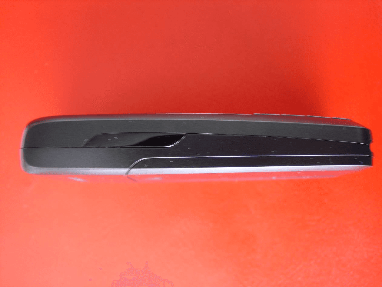
Click to zoom
Application Details
- Equipment Class
- PCE - PCS Licensed Transmitter held to ear
- Date of Grant
- Oct 17, 2005
- Application Purpose
- Original Equipment
- Date of Application
- Oct 17, 2005
- Equipment Note
- GSM 900/1800/1900 Mobile Phone
- Frequency Range
- 1850.20000000 - 1909.80000000
- Company
- BenQ Mobile GmbH & Co. OHG
- Country
- Germany
Documents & Files
Document Text
Text extracted from the exhibit documents filed with the FCC. Open a document above to read the original.
Users Manual
Table of Contents 1 See also Index at the end of this User Guide right page (1) of AX72 Pegasus-DTC, FUG, us-en A31008-H2860-A1-1-7619 (04.10.2005, 16:01) © Siemens AG 2004, E:\Auftrag\Siemens\M obilePhones\FCCs\ax72\FUG\PegasusIVZ.fm VAR Language: en; VAR issue date: 050307 Legal notices ...................................... 3 Safety precautions ............................. 5 Antenna care ................................... 6 Phone operation .............................. 6 Overview of the phone .................... 10 Display symbols ................................ 11 Getting started ................................. 12 Switch on/off, PIN ............................. 13 Emergency number (SOS) .............. 13 General instructions ......................... 14 Standard functions ........................... 15 Security ............................................ 15 Codes ............................................ 15 Calling .............................................. 16 Dialling with number keys .............. 16 End call ......................................... 16 Set volume .................................... 16 Redial ............................................ 16 If the number is busy ..................... 16 Accept call ..................................... 16 Reject call ...................................... 16 Handsfree ...................................... 16 Swapping between 2 calls .............. 17 Conference .................................... 17 Direct call ...................................... 17 Text entry ......................................... 17 Text entry without T9 .................... 17 Special characters .......................... 18 Input menu ................................... 18 Text entry with T9 .......................... 18 Text modules ................................. 19 Default book ..................................... 19 Phonebook ....................................... 20 <New entry> .................................. 20 Call (search for an entry) ................ 20 Change entry ................................. 20 Addressbook .................................... 20 <New entry> ................................. 20 Change entry ................................ 20 Call (search for an entry) ............... 20 Voice dialling ................................. 21 Groups .......................................... 21 Records ............................................ 21 Duration/charges ............................. 22 Voice message/mailbox ................... 22 SMS .................................................. 23 MMS ................................................. 23 Message lists/settings ...................... 24 Ring tones ........................................ 25 Ringer setting ................................ 25 Silent alert ..................................... 25 Volume ......................................... 25 More tones... ................................. 25 Surf & fun ......................................... 26 Internet browser ........................... 26 Games & more .............................. 26 Setup ................................................ 27 Profiles .......................................... 27 Display .......................................... 28 Call setup ...................................... 28 Clock ............................................. 29 Connectivity .................................. 29 Security ......................................... 30 Network ........................................ 31 Accessories ................................... 31 Organiser ......................................... 32 Alarm clock ................................... 32 Calendar ....................................... 32 Appointments ............................... 32 Notes ............................................ 33 Missed alarms ............................... 33 Time zones .................................... 33 Calendar setup .............................. 33 See also In- dex at the end of this User Guide Table of Contents 2 Table of Contents See also Index at the end of this User Guide © Siemens AG 2004, E:\Auftrag\Siemens\Mob ilePhones\FCCs\ax72\FUG\PegasusIVZ.fm left page (2) of AX72 Pegasus-DTC, FUG, us-en, A31008-H2860-A1-1-7619 (04.10.2005, 16:01) VAR Language: en; VAR issue date: 050307 Extras ................................................ 33 Fast access key ................................. 36 Own stuff .......................................... 36 Customer Care .................................. 38 Care and maintenance ..................... 39 Product data ..................................... 40 SAR ................................................... 41 Accessories ....................................... 41 U.S. FDA ............................................ 42 FCC/Industry Canada Notice ............. 46 Intellectual Property ........................ 47 Ten Driving Safety Tips .................... 48 End user license agreement ............. 50 Index ................................................ 53 3 Legal notices right page (3) of AX72 Pegasus-DTC, FUG, us-en A31008-H2860-A1-1-7619 (04.10.2005, 16:00) © Siemens AG 2004, E:\Auftrag\Siemens\Mob ilePhones\FCCs\ax72\FUG\am_LegalNotices.fm VAR Language: en; VAR issue date: 050307 Legal notices The mobile phone described in this guide is approved for use on the GSM and GPRS net- works operating on the GSM 900, 1800 (DCS/PCN) and 1900 (PCS) bands. It is approved for use in the country where it was originally sold and may be approved for use in other countries. © 2005 Siemens Information and Communication Mobile, LLC. All rights reserved. Siemens and the AX72 model phone are trademarks or registered trademarks of Siemens AG and/or its affiliates in the United States and/or other countries. T9® is a registered trademark of America Online, Inc. in the United States. Java and all Java-based trademarks and logos are trademarks or registe…
Text truncated - open the document above for the full version.
Cover Letter(s)
Siemens Communications Haidenauplatz 1 81667 München Germany Tel. +49 89 722 37148 Federal Communication Commission Equipment Authorization Division, Application Processing Branch 7435 Oakland Mills Road Columbia, MD 21048 October 6, 2005 TO WHOM IT MAY CONCERN Pursuant to Paragraphs §0.457 and §0.459 of the Commission’s Rules (47 C.F.R.) and Section §552(b)(4) of the Freedom of Information Act, Siemens Communications requests confidentiality for the following products: FCC ID Number Product Title/Model PWX–AX72 Tri -Band/AX72 For the product stated above, we request that the following information be held confidential: 1) Electrical Schematics of the Circuitry 2) Block Diagram 3) Parts List 4) Technical Description Required for section 2.1003 (c) • Operational Description 5) Tune-up Procedure No other items submitted as part of the equipment authorization filing process are deemed confidential. The above exhibits contain Siemens Communications trade secrets and proprietary information that could be of benefit to our competitors regarding the design of our mobile handset. This material is not customarily available to the general public and we request that it be withheld from public inspection. If you have any questions, please feel free to contact me at the address shown below. Sincerely, Dr. Martin Weinberger Engineering Manager
External Photos
SIEMENS Communications, Inc AX72 Front View. SIEMENS Communications, Inc AX72 Back View SIEMENS Communications, Inc AX72 Side View SIEMENS Communications, Inc AX72 Side View
ID Label/Location Info
Date 20.09.2005 Approval label Name Li Gang AX72/IMEI-Label/Standard 1 25.04.05 Li_G MP PD LPD Z30880-Z9999-Z27-* 2 20.09.05 Li_G LETTERING PLAN Version Date Token SIEMENS AG DIS 186161 Page 1 From 1 A24850-V1-A4-2 VORSTD.DOC White label with black lettering Figure 1 Placement of IMEI label on AX72 Label according to: DIS 186161
Internal Photos
SIEMENS Communications, Inc AX72 Open Battery Cover (Final label: See extra exhibit) SIEMENS Communications, Inc AX72 Disassembly Step 1 SIEMENS Communications, Inc AX72 Disassembly Step 2 SIEMENS Communications, Inc AX72 Back view shields removed SIEMENS Communications, Inc AX72 RF module chamber SIEMENS Communications, Inc AX72 Display module removed SIEMENS Communications, Inc AX72 Tri-Band Antenna
RF Exposure Info
DAT-P-152/98-01 SAR Report Siemens_6620_545_FCC_1900_Cal Data_AX72 Appendix for the Report Dosimetric Assessment of the Portable Device Siemens AX72 (FCC ID: PWX-AX72) According to the FCC Requirements Calibration Data September 29, 2005 IMST GmbH Carl-Friedrich-Gauß-Str. 2 D-47475 Kamp-Lintfort Customer Siemens Information & Communication Mobile LLC 16475 West Bernado Drive, Suite 400 San Diego-CA 92127 This report shall not be reproduced except in full without the written approval of the testing laboratory.
RF Exposure Info
DAT-P-152/98-01 SAR Report, Siemens_6620_545_FCC_1900_SAR Plots_AX72 Page 1 of 15 Appendix for the Report Dosimetric Assessment of the Siemens AX72 (FCC ID: PWX-AX72) According to the FCC Requirements SAR Distribution Plots September 29, 2005 IMST GmbH Carl-Friedrich-Gauß-Str. 2 D-47475 Kamp-Lintfort Customer Siemens Communication Inc. 16475 West Bernado Drive, Suite 400 San Diego CA 92127 The test results only relate to the items tested. This report shall not be reproduced except in full without the written approval of the testing laboratory. dasy_report_fcc_1900_plots_1.1.doc/08.07.2005/CH SAR Report, Siemens_6620_545_FCC_1900_SAR Plots_AX72 Page 2 of 15 dasy_report_fcc_1900_plots_1.1.doc/08.07.2005/CH Table of Contents 1 SAR DISTRIBUTION PLOTS, PCS 1900 HEAD WITHOUT CAMERA.................................................. 3 2 SAR DISTRIBUTION PLOTS, PCS 1900 HEAD WITH CAMERA.......................................................... 7 3 SAR DISTRIBUTION PLOTS, PCS 1900 BODY WITHOUT ACCESSORY........................................ 11 4 SAR DISTRIBUTION PLOTS, PCS 1900 BODY WITH HEADSET....................................................... 12 5 SAR DISTRIBUTION PLOTS, GPRS 1900 BODY WITH DATA CABLE............................................. 13 6 SAR Z-AXIS SCANS (VALIDATION)......................................................................................................... 14 7 SAR Z-AXIS SCANS (MEASUREMENTS)................................................................................................ 15 SAR Report, Siemens_6620_545_FCC_1900_SAR Plots_AX72 Page 3 of 15 dasy_report_fcc_1900_plots_1.1.doc/08.07.2005/CH 1 SAR Distribution Plots, PCS 1900 Head without camera Test Laboratory: IMST GmbH, DASY Blue (I); File Name: 855bplm_1.da4 DUT: Siemens; Type: AX72; Serial: 004400013392855 Program Name: Cheek Left Communication System: GSM 1900; Frequency: 1880 MHz;Duty Cycle: 1:8.3 Medium parameters used: f = 1880 MHz; σ = 1.44 mho/m; ε r = 41.6; ρ = 1000 kg/m 3 Phantom section: Left Section DASY4 Configuration: - Probe: ET3DV6R - SN1669; ConvF(5.11, 5.11, 5.11); Calibrated: 13.01.2005 - Sensor-Surface: 4mm (Mechanical Surface Detection) - Electronics: DAE4 Sn631; Calibrated: 07.07.2005 - Phantom: SAM Glycol 1176; Type: Speag; Serial: 1176 - Measurement SW: DASY4, V4.5 Build 19; Postprocessing SW: SEMCAD, V1.8 Build 146 Cheek Left/Area Scan (6x10x1): Measurement grid: dx=15mm, dy=15mm Maximum value of SAR (measured) = 0.410 mW/g Cheek Left/Zoom Scan (7x7x7)/Cube 0: Measurement grid: dx=5mm, dy=5mm, dz=5mm Reference Value = 15.7 V/m; Power Drift = -0.118 dB Peak SAR (extrapolated) = 0.657 W/kg SAR(1 g) = 0.416 mW/g; SAR(10 g) = 0.241 mW/g Maximum value of SAR (measured) = 0.464 mW/g Cheek Left/Zoom Scan (7x7x7)/Cube 1: Measurement grid: dx=5mm, dy=5mm, dz=5mm Reference Value = 15.7 V/m; Power Drift = -0.118 dB Peak SAR (extrapolated) = 0.408 W/kg SAR(1 g) = 0.275 mW/g; SAR(10 g) = 0.180 mW/g Maximum value of SAR (measured) = 0.313 mW/g Fig. 1: SAR distribution for PCS 1900, channel 661, cheek position, left side of head (September 26, 2005; Ambient Temperature: 21.4∞ C; Liquid Temperature : 20.9∞ C). SAR Report, Siemens_6620_545_FCC_1900_SAR Plots_AX72 Page 4 of 15 dasy_report_fcc_1900_plots_1.1.doc/08.07.2005/CH Test Laboratory: IMST GmbH, DASY Blue (I); File Name: 855bplm_2.da4 DUT: Siemens; Type: AX72; Serial: 004400013392855 Program Name: Tilted Left Communication System: GSM 1900; Frequency: 1880 MHz;Duty Cycle: 1:8.3 Medium parameters used: f = 1880 MHz; σ = 1.44 mho/m; ε r = 41.6; ρ = 1000 kg/m 3 Phantom section: Left Section DASY4 Configuration: - Probe: ET3DV6R - SN1669; ConvF(5.11, 5.11, 5.11); Calibrated: 13.01.2005 - Sensor-Surface: 4mm (Mechanical Surface Detection) - Electronics: DAE4 Sn631; Calibrated: 07.07.2005 - Phantom: SAM Glycol 1176; Type: Speag; Serial: 1176 - Measurement SW: DASY4, V4.5 Build 19; Postprocessing SW: SEMCAD, V1.8 Build 146 Tilted Left/Area Scan (6x10x1): Measurement grid: dx=15mm, dy=15mm Maximum value of SAR (measured) = 0.503 mW/g Tilted Left/Zoom Scan (7x7x7)/Cube 0: Measurement grid: dx=5mm, dy=5mm, dz=5mm Reference Value = 17.5 V/m; Power Drift = 0.01 dB Peak SAR (extrapolated) = 0.851 W/kg SAR(1 g) = 0.530 mW/g; SAR(10 g) = 0.297 mW/g Maximum value of SAR (measured) = 0.592 mW/g Fig. 2: SAR distribution for PCS 1900, channel 661, tilted position, left side of head (September 26, 2005; Ambient Temperature: 21.3∞ C; Liquid Temperature : 20.9∞ C). SAR Report, Siemens_6620_545_FCC_1900_SAR Plots_AX72 Page 5 of 15 dasy_report_fcc_1900_plots_1.1.doc/08.07.2005/CH Test Laboratory: IMST GmbH, DASY Blue (I); File Name: 855bprm_1.da4 DUT: Siemens; Type: AX72; Serial: 004400013392855 Program Name: Cheek Right Communication System: GSM 1900; Frequency: 1880 MHz;Duty Cycle: 1:8.3 Medium parameters used: f = 1880 MHz; σ = 1.44 mho/m; ε r = 41.6; ρ = 1000 kg/m 3 Phantom section: Right Section DASY4 Configuration: - Probe: ET3DV6R - SN1669; ConvF(5.11, 5.11, 5.11); Calibrated: 13.01.2005 - Sensor-Surface: 4mm (Mechanical Surface Detection) - Electronics: DAE4 Sn631; Calibrated: 07.07.2005 - Phantom: SAM Glycol 1176; Type: Speag; Serial: 1176 - Measurement SW: DASY4, V4.5 Build 19; Postprocessing SW: SEMCAD, V1.8 Build 146 Cheek Right/Area Scan (6x10x1): Measurement grid: dx=15mm, dy=15mm Maximum value of SAR (measured) = 0.345 mW/g Cheek Right/Zoom Scan (7x7x7)/Cube 0: Measurement grid: dx=5mm, dy=5mm, dz=5mm Reference Value = 16.1 V/m; Power Drift = -0.181 dB Peak SAR (extrapolated) = 0.528 W/kg SAR(1 g) = 0.346 mW/g; SAR(10 g) = 0.208 mW/g Maximum value of SAR (measured) = 0.386 mW/g Fig. 3: SAR distribution for PCS 1900, channel 661, cheek position, right side of head (September 26, 2005; Ambient Temperature: 21.3∞ C; Liquid Temperature : 20.9∞ C). SAR Report, Siemens_6620_545_FCC_1900_SAR Plots_AX72 Page 6 of 15 dasy_report_fcc_1900_plots_1.1.doc/08.07.2005/CH Test Laboratory: IMST GmbH, DASY Blue (I); File Name: 855bprm_2.da4 DUT: Siemens; Type: …
Text truncated - open the document above for the full version.
RF Exposure Info
DAT-P-152/98-01 SAR Report, Siemens_6620_545_FCC_1900_AX72 Page 1 of 38 Report Dosimetric Assessment of the Portable Device Siemens AX72 (FCC ID: PWX-AX72) According to the FCC Requirements September 28, 2005 IMST GmbH Carl-Friedrich-Gauß-Str. 2 D-47475 Kamp-Lintfort Customer Siemens Information & Communication Mobile LLC 16475 West bernado Drive, Suite 400 CA 92127 San Diego The test results only relate to the items tested. This report shall not be reproduced except in full without the written approval of the testing laboratory. dasy_report_fcc_1900_4.4.doc/14.09.2005/ABo SAR Report, Siemens_6620_545_FCC_1900_AX72 Page 2 of 38 dasy_report_fcc_1900_4.4.doc/14.09.2005/ABo Executive Summary The AX72 is a mobile phone (Portable Device) from Siemens operating in the 900 MHz, 1800 MHz and 1900 MHz frequency range. The device has an integrated antenna and the system concepts used are the GSM 900, GSM 1800 and PCS 1900 standards including GPRS Class 8 The objective of the measurements done by IMST was the dosimetric assessment of one device in the PCS 1900 standard with and without cam. The examinations have been carried out with the dosimetric assessment system ÑDASY4ì. The measurements were made according to the Supplement C to OET Bulletin 65 of the Federal Communications Commission (FCC) Guidelines [OET 65] for evaluating compliance of mobile and portable devices with FCC limits for human exposure (general population) to radiofrequency emissions. All measurements have been performed in accordance to the recommendations given by SPEAG. The Siemens AX72 mobile phone (FCC ID: PWX-AX72) is in compliance with the Federal Communications Commission (FCC) Guidelines [OET 65] for uncontrolled exposure. The phone was tested in addition to the head positions in the following configurations: Body worn with the following accessories: • GSM with and without headset (0mm distance) • GPRS (Class 8) with data cable (0mm distance) prepared by: ........................................... reviewed by: ..................................... Alexander Rahn AndrÈ van den Bosch test engineer quality assurance engineer IMST GmbH Carl-Friedrich-Gaufl-Strafle 2 D-47475 Kamp-Lintfort Tel. +49- 2842-981 378 Fax +49- 2842-981 399 email: [email protected] SAR Report, Siemens_6620_545_FCC_1900_AX72 Page 3 of 38 dasy_report_fcc_1900_4.4.doc/14.09.2005/ABo Table of Contents 1 SUBJECT OF INVESTIGATION.................................................................................................................... 4 2 THE IEEE STANDARD C95.1 AND THE FCC EXPOSURE CRITERIA................................................. 4 2.1 DISTINCTION BETWEEN EXPOSED POPULATION, DURATION OF EXPOSURE AND FREQUENCIES........... 4 2.2 DISTINCTION BETWEEN MAXIMUM PERMISSIBLE EXPOSURE AND SAR LIMITS....................................... 5 2.3 SAR LIMIT.................................................................................................................................................. 5 3 THE FCC MEASUREMENT PROCEDURE................................................................................................. 6 3.1 GENERAL REQUIREMENTS......................................................................................................................... 6 3.2 DEVICE OPERATING NEXT TO A PERSON’S EAR....................................................................................... 6 4 BODY-WORN CONFIGURATIONS.............................................................................................................. 9 4.1 POC (PTT) POSITION...............................................................................................................................9 4.2 PHANTOM REQUIREMENTS...................................................................................................................... 10 4.3 TEST TO BE PERFORMED......................................................................................................................... 10 5 THE MEASUREMENT SYSTEM................................................................................................................. 10 5.1 PHANTOM................................................................................................................................................. 12 5.2 PROBE...................................................................................................................................................... 12 5.3 MEASUREMENT PROCEDURE.................................................................................................................. 13 5.4 UNCERTAINTY ASSESSMENT................................................................................................................... 14 6 SAR RESULTS............................................................................................................................................... 15 7 EVALUATION................................................................................................................................................. 18 8 APPENDIX....................................................................................................................................................... 20 8.1 ADMINISTRATIVE DATA............................................................................................................................ 20 8.2 DEVICE UNDER TEST AND TEST CONDITIONS......................................................................................... 20 8.3 TISSUE RECIPES...................................................................................................................................... 21 8.4 MATERIAL PARAMETERS......................................................................................................................... 21 8.5 SIMPLIFIED PERFORMANCE CHECKING................................................................................................... 22 8.6 ENVIRONMENT.........................…
Text truncated - open the document above for the full version.
Test Report
1 of 5 ________________________________________________________________________________ Siemens Communications, Inc Project: AX72 Date: 19-09-2005 Test case: Conducted power report Page: 1 of 5 - 1 - Report No: FCC_AX72.doc Test Report Conducted Output power GSM 1900 Report No: FCC_AX72 Issue date: September 19, 2005 Test Site: Siemens A/S Mobile Phones Development ICM MP PD HW 1 AAL 1 DK-9400 Noerresundby Denmark Tel.: +45 72 19 50 00 Fax.: +45 72 19 50 02 Arne Bisgaard Kristensen Part Project Leader EMC & Antenna Morten Christensen Line Group Manager EMC & Antenna 2 of 5 ________________________________________________________________________________ Siemens Communications, Inc Project: AX72 Date: 19-09-2005 Test case: Conducted power report Page: 2 of 5 - 2 - Report No: FCC_AX72.doc Contents 1 Objective and Method............................................................................... 3 2 Results........................................................................................................ 3 2.1 GSM 1900 .............................................................................................................. 3 3 Minutes of Test .......................................................................................... 3 3.1 Description of device under test ............................................................................. 3 3.2 Measurement Set-up .............................................................................................. 4 4 Calibration Certificate ............................................................................... 5 3 of 5 ________________________________________________________________________________ Siemens Communications, Inc Project: AX72 Date: 19-09-2005 Test case: Conducted power report Page: 3 of 5 - 3 - Report No: FCC_AX72.doc 1 Objective and Method FCC approval for mobile phones requires reporting output power at RF output terminal pursuant to title 47 CFR part 2.1046. SIEMENS devices feature a special 50 Ohm RF connector suitable for such measurements. Using a special adapter and connecting the phone to an appropriate load in terms of the input port of the measurement equipment used, we hereby report the values for highest power setting. 2 Results 2.1 GSM 1900 Average Power during burst at connector Device Ch. 512 1850.2 MHz Ch. 661 1880.0 MHz Ch. 810 1909.8 MHz Siemens AX72, SAR IMEI: 0044000013393010 + 29.61 dBm + 29.22 dBm + 28.87 dBm Siemens AX72, SAR IMEI: 0044000013392855 + 29.69 dBm + 29.31 dBm + 28.97 dBm Siemens AX72, FCC test IMEI: 0044000013392392 + 29.70 dBm + 29.31 dBm + 28.96 dBm Siemens AX72, FCC test IMEI: 0044000013393200 + 29.70 dBm + 29.32 dBm + 28.98 dBm Table 2: Results of power measurements at connector in the GSM 1900 Band 3 Minutes of Test 3.1 Description of device under test Mobile phone: Siemens AX72 Frequency range GSM 1900: 1850 – 1990 MHz Siemens Part number: L36880-N2860-xxxx FCC ID: PWX-AX72 IC ID: 267E-AX72 4 of 5 ________________________________________________________________________________ Siemens Communications, Inc Project: AX72 Date: 19-09-2005 Test case: Conducted power report Page: 4 of 5 - 4 - Report No: FCC_AX72.doc 3.2 Measurement Set-up Figure 1: Block Diagram of set-up for conducted power measurement Figure 2: Set-up for conducted power measurement Base Station Simulator DUT Special Adapter 5 of 5 ________________________________________________________________________________ Siemens Communications, Inc Project: AX72 Date: 19-09-2005 Test case: Conducted power report Page: 5 of 5 - 5 - Report No: FCC_AX72.doc 4 Calibration Certificate
Test Report
TTI-P-G 081/94-A0 Accredited according to ISO/IEC 17025 Bluetooth Qualification Test Facility (BQTF) FCC listed # 101450 IC recognized # 3925 CETECOM Inc. 411 Dixon Landing Road Milpitas, CA 95035 U.S.A. Phone: + 1 (408) 586 6200 Fax: + 1 (408) 586 6299 E-mail: [email protected] http://www.cetecom.com CETECOM Inc. is a Delaware Corporation with Corporation number: 2113686 Board of Directors: Dr. Harald Ansorge, Dr. Klaus Matkey, Hans Peter May © Copyright by CETECOM FCC Test Report FCC Part 24 / RSS 133 FOR: TRI-BAND GSM MOBILE PHONE MODEL #: AX72 SIEMENS COMMUNICATIONS HAIDENAUPLATZ 1 81667 MUNCHEN GERMANY FCC ID: PWX-AX72 IC ID: 267E-AX72 TEST REPORT #: EMC_1054_2005_FCC24 DATE: OCTOBER 04, 2005 Test Report #: EMC_1054_2005_FCC24 Date of Report: 2005-10-04 Page 2 of 59 This report shall not be reproduced except in full without the written approval of: CETECOM, Inc. Table of Contents 1 ASSESSMENT .................................................................................................................................... 3 2 ADMINISTRATIVE DATA............................................................................................................... 4 2.1 IDENTIFICATION OF THE TESTING LABORATORY ISSUING THE EMC TEST REPORT......................... 4 2.2 IDENTIFICATION OF THE CLIENT................................................................................................... 4 2.3 IDENTIFICATION OF THE MANUFACTURER.................................................................................... 4 3 EQUIPMENT UNDER TEST (EUT) ................................................................................................ 5 3.1 IDENTIFICATION OF THE EQUIPMENT UNDER TEST....................................................................... 5 4 SUBJECT OF INVESTIGATION..................................................................................................... 6 5 MEASUREMENTS............................................................................................................................. 7 5.1 RF POWER OUTPUT....................................................................................................................... 7 5.1.1 FCC 2.1046 Measurements required: RF power output....................................................... 7 5.1.2 Limits: ................................................................................................................................... 7 5.1.2.1 FCC 24.232 (b)(c) Power limits. ....................................................................................... 7 5.1.3 Conducted Output Power Measurement procedure:............................................................. 7 5.1.4 Results 1900 MHz band(conducted): .................................................................................... 8 5.1.5 Radiated Output Power Measurement procedure:................................................................ 9 5.1.6 EIRP Results 1900 MHz band:............................................................................................ 10 5.2 OCCUPIED BANDWIDTH/EMISSION BANDWIDTH........................................................................ 14 5.2.1 FCC 2.1049 Measurements required: Occupied bandwidth............................................... 14 5.2.2 Occupied / emission bandwidth measurement procedure:.................................................. 14 5.2.3 Occupied / Emission bandwidth results 1900 MHz band: .................................................. 15 5.3 FREQUENCY STABILITY............................................................................................................... 22 5.3.1 Limit .................................................................................................................................... 22 5.3.2 FREQUENCY STABILITY (PCS-1900) .............................................................................. 23 5.4 SPURIOUS EMISSIONS CONDUCTED............................................................................................. 24 5.4.1 FCC 2.1051 Measurements required: Spurious emissions at antenna terminals. .............. 24 5.4.2 Limits: ................................................................................................................................. 24 5.4.2.1 FCC 24.238 Emission limitations for Broadband PCS equipment. ............................... 24 5.4.3 Conducted out of band emissions measurement procedure: ............................................... 24 5.4.4 Bandedge Results PCS-1900 ............................................................................................... 26 5.4.5 Conducted Spurious Results PCS-1900 .............................................................................. 28 5.5 SPURIOUS EMISSIONS RADIATED................................................................................................ 32 5.5.1 FCC 2.1053 Measurements required: Field strength of spurious radiation....................... 32 5.5.2 Limits: ................................................................................................................................. 32 5.5.2.1 FCC 24.238 Emission limitations for Broadband PCS equipment. ............................... 32 5.5.3 Radiated out of band measurement procedure: .................................................................. 33 5.6 RECEIVER RADIATED EMISSIONS § 2.1053 / RSS-133 .................................................... 50 5.6.1 Receiver Spurious on EUT ......................................................................…
Text truncated - open the document above for the full version.
Contact Information
Applicant
Dr. Martin Weinberger(Engineering Manager)
Test Firm
Cetecom Inc.Lothar Schmidt
Technical Specifications
| # | Rule Parts | Frequency Range | Power Output | Emission | Tolerance |
|---|---|---|---|---|---|
| 1 | 24E | 1.85 GHz - 1.91 GHz | 873.00 mW | 300KGXW | 0.0200000000 ppm |
Other Applications from BenQ Mobile GmbH & Co. OHG
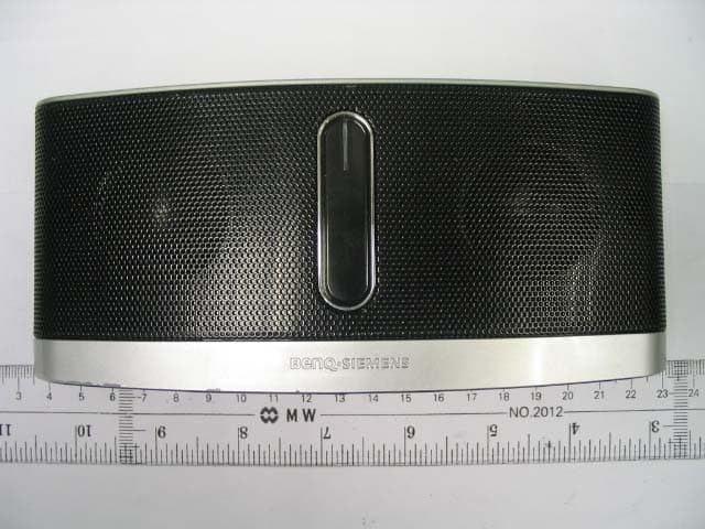
PWX-IMS100
Nov 09, 2006Mobile Sound Set Bluetooth
Equipment Class
DSS - Part 15 Spread Spectrum Transmitter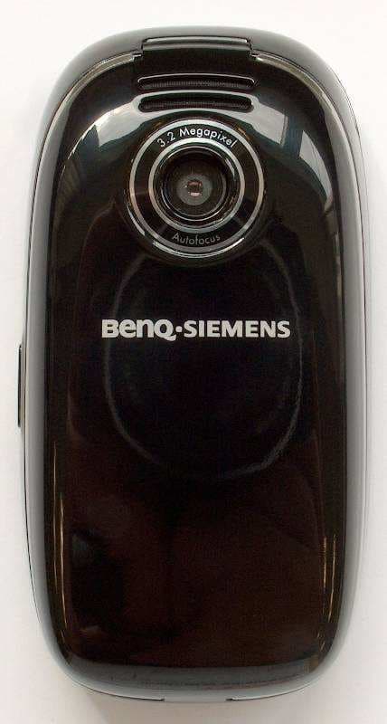
PWX-SL91
Sep 13, 2006GSM 900/1800/1900, UMTS Mobile Phone with BT
Equipment Class
PCE - PCS Licensed Transmitter held to ear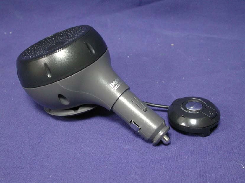
PWX-HKW100
Aug 30, 2006HKW-100 CK Bluetooth Easy
Equipment Class
DSS - Part 15 Spread Spectrum Transmitter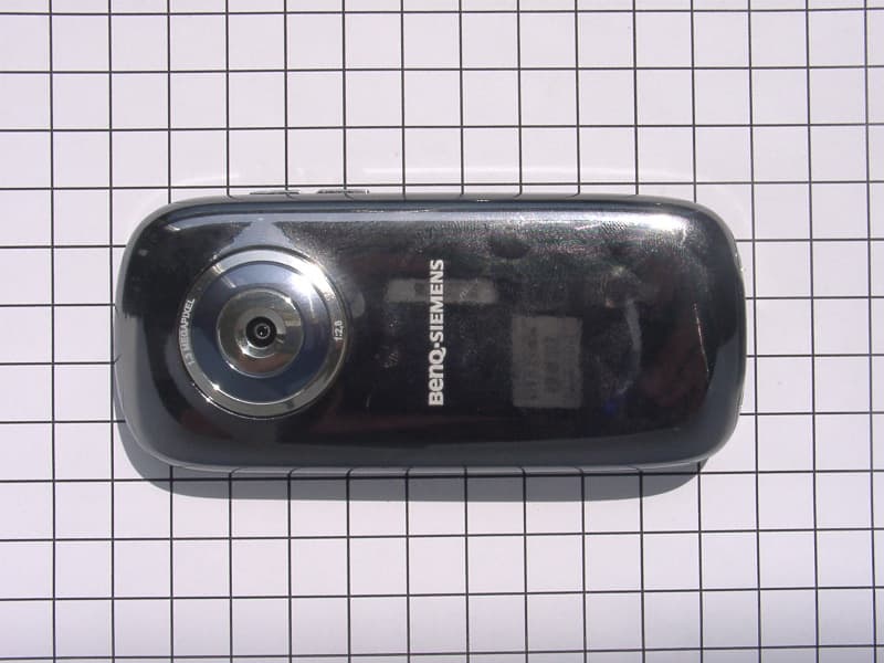
PWX-E71A
Aug 09, 2006GSM 850/1800/1900 Mobile Phone with BT
Equipment Class
DSS - Part 15 Spread Spectrum Transmitter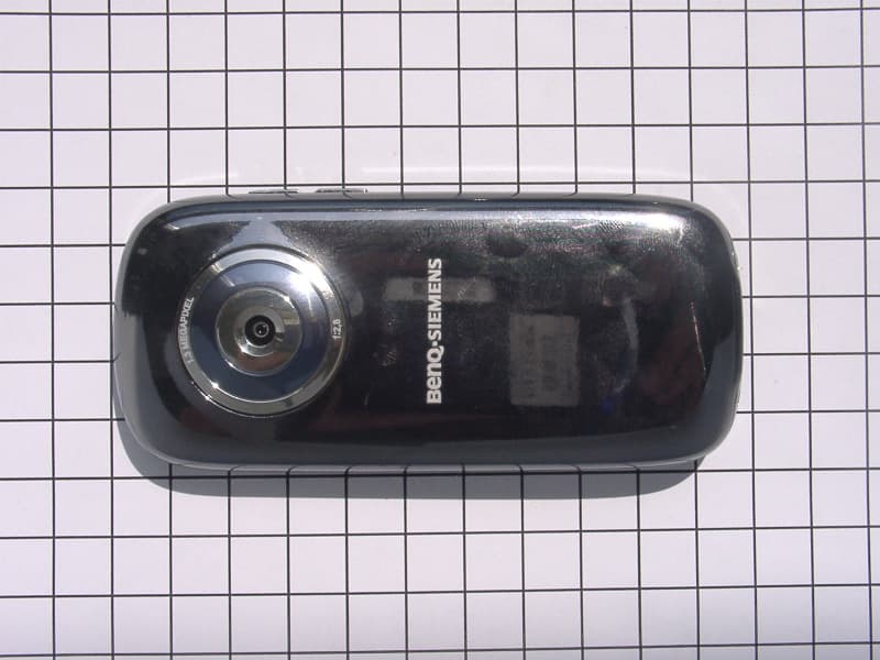
PWX-E71
Aug 09, 2006GSM 900/1800/1900 Mobile Phone with BT and FM Rece
Equipment Class
DSS - Part 15 Spread Spectrum Transmitter