PWX-HHB130Headset Bluetooth Clip
BenQ Mobile GmbH & Co. OHG
Click to zoom
Application Details
- Equipment Class
- DSS - Part 15 Spread Spectrum Transmitter
- Date of Grant
- May 15, 2006
- Application Purpose
- Original Equipment
- Date of Application
- May 15, 2006
- Equipment Note
- Headset Bluetooth Clip
- Frequency Range
- 2402.00000000 - 2480.00000000
- Company
- BenQ Mobile GmbH & Co. OHG
- Country
- Germany
Documents & Files
Document Text
Text extracted from the exhibit documents filed with the FCC. Open a document above to read the original.
Users Manual
Headset Bluetooth Clip Brand Name: BenQ-Siemens Model Name: HHB-130 Headset Bluetooth Clip (en) © Siemens AG 2005, C:\_Christine\Accessories\neuer Projektordner\HHB-130_131_Headset_B_Clip\05GUW00103 left page (2) of Headset Bluetooth Clip HHB-130/131en, A31008-XXXX (25.04.2006, 2 Template: X75, Version 2.2;VAR Language: unknown; VAR issue date: VAR_Issue_DATE Safety precautions Please read the user guide and safety precautions carefully before use! Explain the content to your children and the hazards associated with using the device. Remember to comply with legal requirements and lo- cal restrictions when using the device. For example in aeroplanes, petrol sta- tions, hospitals or while driving. The functioning of medical devices such as hearing aids or pacemakers can be impaired. Keep at least 20cm/9 inches between the clip and the pacemak- er. For more information consult your doctor. Caution! Young children may choke on small parts. The device must therefore be stored out of the reach of small children. The mains voltage speci- fied on the power adapter must not be exceeded. Otherwise the charger may be destroyed. To charge the battery, plug the power adapter into an easily accessible mains power socket. The only way to turn off the charger after charging the battery is to unplug it. Do not throw the device into an open fire. Use only original charging devices. Otherwise serious damage to health or prop- erty may result. The bat- tery could explode, for example. The device may only be opened by authorised service partners. Any changes to this device are strictly prohibited and will invalidate the operating licence. Headset Bluetooth ® Stereo (en) right page (3) of Headset Bluetooth Clip HHB-130/131en A31008-XXXX (25.04.2006, © S i emens A G 2 0 0 5 , C : \ _ C h r i st i ne \ A ccessor i es \ neuer P ro j e k tor d ner \ H H B - 1 3 0 _ 1 3 1 _ H ea d set_ B _ C l i p \ 0 5 G U W 0 0 1 0 3 3 T emp l ate: X 7 5 , V ers i on 2 . 2 ; V A R L anguage: un k nown; V A R i ssue d ate: V A R _ I ssue _ D A T E Important: Compatibility The Headset Bluetooth ® Clip (referred to hereafter as "headset") is suitable for telephoning with mobile phones with the Bluetooth Profile (Headset Profile or Handsfree Profile). Bluetooth ® technology The headset and the mobile phone communicate by means of Bluetooth ® , a short-range radio link. To enable this communication, the headset and mobile phone must be paired with each other. For more infor- mation please read "Establishing the first connection with the mobile phone (pairing)", (page 7). Dispose of unusable de- vices and their accesso- ries according to the legal regulations. The device may cause in- terference in the vicinity of TV sets, radios and PCs. Use only original accesso- ries. This will avoid poten- tial damage to health or property and ensure com- pliance with all relevant regulations. Improper use will invalidate the guarantee! Permanent hearing loss may occur if you use ear- or headphones at high volume.You can adapt over time to a higher volume, which may sound nor- mal but can be damaging to your hear- ing. Set your volume to a safe level. If you experience ringing in your ears, reduce the volume or discontinue use of your system. In some countries there may be re- strictions to the use of Bluetooth ® de- vices. Please make enquiries at the authorities responsible. The rights to the Bluetooth ® word- mark and the Bluetooth ® logos are owned by the Bluetooth ® SIG, Inc. Any use of such marks by BenQ Corp. is under license. Other trademarks and trade names are those of their respective owners. Please also read the notes on Bluetooth ® links in your mobile phone user guide as the controls and dis- play messages differ between phones. Headset Bluetooth Clip (en) © Siemens AG 2005, C:\_Christine\Accessories\neuer Projektordner\HHB-130_131_Headset_B_Clip\05GUW00103 left page (4) of Headset Bluetooth Clip HHB-130/131en, A31008-XXXX (25.04.2006, 4 Template: X75, Version 2.2;VAR Language: unknown; VAR issue date: VAR_Issue_DATE Overview of headset 1 Earphone 2 a On/Off button/ Multifunction button Press briefly: Activate voice dialling or Accept a call Press and hold: End a call 3 Microphone 4 LED signals different headset states (page 8) 5 Volume buttons Press – button: quieter Press + button: louder 6 Clip Please ensure that the clip is se- curely attached to the garment. The place where the clip is at- tached should not be too thick. 7 Charger socket 8 Parking position for the earphone 9 Charger 1 Headset Bluetooth ® Stereo (en) right page (5) of Headset Bluetooth Clip HHB-130/131en A31008-XXXX (25.04.2006, © S i emens A G 2 0 0 5 , C : \ _ C h r i st i ne \ A ccessor i es \ neuer P ro j e k tor d ner \ H H B - 1 3 0 _ 1 3 1 _ H ea d set_ B _ C l i p \ 0 5 G U W 0 0 1 0 3 5 T emp l ate: X 7 5 , V ers i on 2 . 2 ; V A R L anguage: un k nown; V A R i ssue d ate: V A R _ I ssue _ D A T E Getting started Wearing the headset correctly Wear the headset as shown in the diagram. The microphone- opening must always point towards your mouth. Charging the headset The battery is not fully charged when delivered. To charge the headset you will need the charger included in the delivery package. Please remem- ber that the power socket must be close by and freely accessible. 9 Headset Bluetooth Clip (en) © Siemens AG 2005, C:\_Christine\Accessories\neuer Projektordner\HHB-130_131_Headset_B_Clip\05GUW00103 left page (6) of Headset Bluetooth Clip HHB-130/131en, A31008-XXXX (25.04.2006, 6 Template: X75, Version 2.2;VAR Language: unknown; VAR issue date: VAR_Issue_DATE 1. Plug the charger9 into the headset 7 as shown. 2. Plug the power connector of the charger into a mains po- wer socket. The device is not ready for oper- ation while charging. It switches off automatically during charg- ing and must be switched on again when charging is completed. Charging time After two hours the battery is ap- proximately 80% charged; the device needs about 3.5 hours to charg…
Text truncated - open the document above for the full version.
External Photos
Page 1 CONSTRUCTION PHOTOS OF EUT Page 2
ID Label/Location Info
haoyu.lee hongmin.hu jing.wang 04/17`06 04/17`06 04/17`06 50-81102SIG0 1 1/1 A4 DATE CODE SEE NOTE 1 BenQ PART NO FCC ID NOTE: 1. Year 1998 1999 2000 2001 2002 2003 2004 2005 2006 2007 2008 2009 Letter K L M N P R S T U V W X Month January February March April May June July August September October Nocember December Number 1 2 3 4 5 6 7 8 9 O N D 4
Internal Photos
Page 3 Page 4 Page 5 Page 6
Operational Description
FCC ID: PWX-HHB130 Report No.: RF950406L01 Operational Description The transmitter of the EUT (Headset Bluetooth Clip) is powered by battery. The antenna is Chip antenna without antenna connector. For more detailed instruction, please take a look at the user’s manual. This device is a Frequency Hopping device with 79 hopping frequencies.
RF Exposure Info
FCC ID: PWX-HHB130 Report No: SA950406L01 1 RF EXPOSURE REPORT REPORT NO.: SA950406L01 MODEL NO.: HHB-130 ACCORDING: FCC Guidelines for Human Exposure IEEE C95.1 APPLICANT: BenQ Mobile GmbH & Co. OHG ADDRESS: Haidenauplatz 1, 81667 Munich , Germany ISSUED BY: Advance Data Technology Corporation LAB ADDRESS: No. 47, 14th Ling, Chia Pau Tsuen, Lin Kou Hsiang 244, Taipei Hsien, Taiwan, R.O.C. TEST LOCATION: No. 19, Hwa Ya 2nd Rd., Wen Hwa Tsuen, Kwei Shan Hsiang, Taoyuan Hsien 333, Taiwan, R.O.C. FCC ID: PWX-HHB130 Report No: SA950406L01 2 RF Exposure Measurement (Portable Device) 1. Introduction In this document, we try to prove the safety of radiation harmfulness to the human body for our product. The limit for Maximum Permissible Exposure (MPE) specified in FCC 1.1310 is followed. The Gain of the antenna used in this product is measured in a Fully Anechoic Chamber (FAC) calibrated for antenna measurement in ADT, and also the maximum total power input to the antenna is measured. Through the Friis transmission formula and the maximum gain of the antenna, we can calculate the distance, away from the product, where the limit of MPE is reached. Although the Friis transmission formula is a far field assumption, the calculated result of that is an over-prediction for near field power density. We will take that as the worst case to specify the safety range. 2. RF Exposure Limit According to FCC 1.1310: The criteria listed in the following table shall be used to evaluate the environmental impact of human exposure to radio-frequency (RF) radiation as specified in 1.1307(b) LIMITS FOR MAXIMUM PERMISSIBLE EXPOSURE (MPE) Frequency Range (MHz) Electric Field Strength (V/m) Magnetic Field Strength (A/m) Power Density (mW/cm 2 ) Average Time (minutes) (A)Limits For Occupational / Control Exposures 300-1500......F/3006 1500-100,000......56 (B)Limits For General Population / Uncontrolled Exposure 300-1500......F/15006 1500-100,000......1.030 F = Frequency in MHz FCC ID: PWX-HHB130 Report No: SA950406L01 3 3. Friis Formula Friis transmission formula: Pd = (Pout*G) / (4*pi*r 2 ) where Pd = power density in mW/cm 2 Pout = output power to antenna in mW G = gain of antenna in linear scale Pi = 3.1416 R = distance between observation point and center of the radiator in cm If we know the maximum Gain of the antenna and the total power input to the antenna, through the calculation, we will know the MPE value at distance 20cm. Ref.: David K. Cheng, Field and Wave Electromagnetics, Second Edition, Page 640, Eq. (11-133). 4 EUT Operating condition The software provided by Manufacturer enabled the EUT to transmit and receive data at lowest, middle and highest channel individually. 5. Classification This device is not fixed inside the AC Adapter that is classified as Portable Device. FCC ID: PWX-HHB130 Report No: SA950406L01 4 6 Conclusion No evaluation required if power is below this threshold: F (GHz)mW Low2.402 High2.480 24.580 Maximum measured transmitter power: Pout (dBm)Pout (mW) Conducted Power 2.31 1.702 EIRP Power 6.31 4.276 *NOTE: The antenna is Chip antenna with 4dBi gain Threshold for no SAR evaluation is 24.580mW. Transmitter power is 4.276mW. Conclusion: No SAR evaluation required since Transmitter Power is below FCC threshold.
Test Report
Report No.: RF950406L011Report Format Version 2.0.4 FCC TEST REPORT REPORT NO.: RF950406L01 MODEL NO.: HHB-130 RECEIVED: Apr. 06, 2006 TESTED: Apr. 09 ~ Apr. 17, 2006 ISSUED: Apr. 20, 2006 APPLICANT: BenQ Mobile GmbH & Co. OHG ADDRESS: Haidenauplatz 1, 81667 Munich , Germany ISSUED BY: Advance Data Technology Corporation LAB ADDRESS: No. 47, 14 th Ling, Chia Pau Tsuen, Lin Kou Hsiang 244, Taipei Hsien, Taiwan, R.O.C. TEST LOCATION: No. 19, Hwa Ya 2 nd Rd., Wen Hwa Tsuen, Kwei Shan Hsiang, Taoyuan Hsien 333, Taiwan, R.O.C. This test report consists of 49 pages in total. It may be duplicated completely for legal use with the approval of the applicant. It should not be reproduced except in full, without the written approval of our laboratory. The client should not use it to claim product endorsement by CNLA, A2LA or any government agencies. The test results in the report only apply to the tested sample. NO. 2177-01 Report No.: RF950406L012Report Format Version 2.0.4 TABLE OF CONTENTS 1.CERTIFICATION ............................................................................................................4 2.SUMMARY OF TEST RESULTS ...................................................................................5 2.1MEASUREMENT UNCERTAINTY .................................................................................5 3.GENERAL INFORMATION ............................................................................................6 3.1 GENERAL DESCRIPTION OF EUT ...............................................................................6 3.2 DESCRIPTION OF TEST MODES .................................................................................7 3.2.1 CONFIGURATION OF SYSTEM UNDER TEST............................................................7 3.2.2 TEST MODE APPLICABILITY AND TESTED CHANNEL DETAIL.................................8 3.3.3 GENERAL DESCRIPTION OF APPLIED STANDARDS ..............................................10 3.3.4 DESCRIPTION OF SUPPORT UNITS.........................................................................10 4. TEST TYPES AND RESULTS ...................................................................................... 11 4.1 CONDUCTED EMISSION MEASUREMENT ............................................................... 11 4.2 RADIATED EMISSION MEASUREMENT .................................................................... 11 4.2.1 LIMITS OF RADIATED EMISSION MEASUREMENT ................................................. 11 4.2.2 TEST INSTRUMENTS .................................................................................................12 4.2.3 TEST PROCEDURES ..................................................................................................13 4.2.4 DEVIATION FROM TEST STANDARD ........................................................................13 4.2.5 TEST SETUP ...............................................................................................................14 4.2.6 EUT OPERATING CONDITIONS.................................................................................14 4.2.7 TEST RESULTS ...........................................................................................................15 4.3 NUMBER OF HOPPING FREQUENCY USED ............................................................19 4.3.1 LIMIT OF HOPPING FREQUENCY USED ..................................................................19 4.3.2 TEST INSTRUMENTS .................................................................................................19 4.3.3 TEST PROCEDURES ..................................................................................................19 4.3.4 DEVIATION FROM TEST STANDARD ........................................................................20 4.3.5 TEST SETUP ...............................................................................................................20 4.3.6 TEST RESULTS ...........................................................................................................20 4.4 DWELL TIME ON EACH CHANNEL ............................................................................22 4.4.1 LIMIT OF DWELL TIME USED ....................................................................................22 4.4.2 TEST INSTRUMENTS .................................................................................................22 4.4.3 TEST PROCEDURES ..................................................................................................22 4.4.4 DEVIATION FROM TEST STANDARD ........................................................................22 4.4.5 TEST SETUP ...............................................................................................................23 4.4.6 TEST RESULTS ...........................................................................................................23 4.5 CHANNEL BANDWIDTH ..............................................................................................27 4.5.1 LIMITS OF CHANNEL BANDWIDTH ...........................................................................27 4.5.2 TEST INSTRUMENTS .................................................................................................27 4.5.3 TEST PROCEDURE ....................................................................................................27 4.5.4 DEVIATION FROM TEST STANDARD ........................................................................28 4.5.5 TEST SETUP ...............................................................................................................28 4.5.6 EUT OPERATING CONDITION ...................................................................................28 4.5.7 TEST RESULTS ...........................................................................................................29 4.6 HOPPING CHANNEL SEPARATION............................................................................32 4.6.1 LIMIT OF HOPPING CH…
Text truncated - open the document above for the full version.
Test Setup Photos
Report No.: RF950406L0147Report Format Version 2.0.4 5. PHOTOGRAPHS OF THE TEST CONFIGURATION RADIATED EMISSION TEST
Contact Information
Applicant
Dr. Martin Weinberger(Engineering Manager)
Technical Contact
Advance Data Technology Corporation (Hwa Ya)Gary Chang
[email protected]886-3-3183232
No. 19, Hwa Ya 2nd Rd., Kwei Shan Hsiang · Taoyuan Hsien · Taiwan
Non-Technical Contact
Advance Data Technology CorporationEllis Wu
[email protected]886-3-3183232
Test Firm
Bureau Veritas CPS (H.K.) Ltd. Taoyuan BranchRichard Chen
Technical Specifications
| # | Rule Parts | Frequency Range | Power Output |
|---|---|---|---|
| 1 | 15C | 2.40 GHz - 2.48 GHz | 2.00 mW |
Other Applications from BenQ Mobile GmbH & Co. OHG
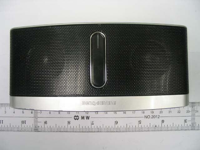
PWX-IMS100
Nov 09, 2006Mobile Sound Set Bluetooth
Equipment Class
DSS - Part 15 Spread Spectrum Transmitter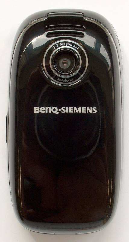
PWX-SL91
Sep 13, 2006GSM 900/1800/1900, UMTS Mobile Phone with BT
Equipment Class
PCE - PCS Licensed Transmitter held to ear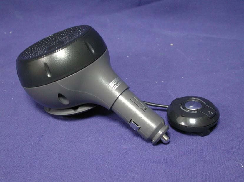
PWX-HKW100
Aug 30, 2006HKW-100 CK Bluetooth Easy
Equipment Class
DSS - Part 15 Spread Spectrum Transmitter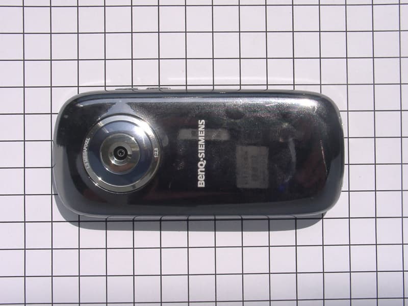
PWX-E71A
Aug 09, 2006GSM 850/1800/1900 Mobile Phone with BT
Equipment Class
DSS - Part 15 Spread Spectrum Transmitter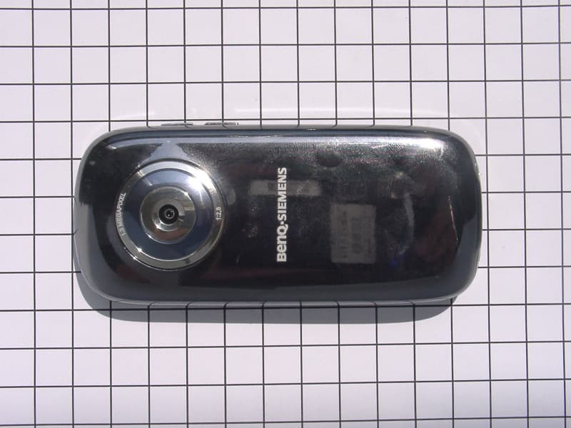
PWX-E71
Aug 09, 2006GSM 900/1800/1900 Mobile Phone with BT and FM Rece
Equipment Class
DSS - Part 15 Spread Spectrum Transmitter