PWX-S46S46
BenQ Mobile GmbH & Co. OHG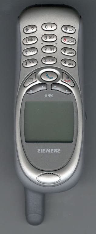
Click to zoom
Application Details
- Equipment Class
- PCE - PCS Licensed Transmitter held to ear
- Date of Grant
- Jan 28, 2002
- Application Purpose
- Original Equipment
- Date of Application
- Nov 11, 2001
- Equipment Note
- S46
- Frequency Range
- 1850.20000000 - 1909.80000000
- Company
- BenQ Mobile GmbH & Co. OHG
- Country
- Germany
Documents & Files
Document Text
Text extracted from the exhibit documents filed with the FCC. Open a document above to read the original.
Users Manual
6. 11.01 S46 US DRAFT A31008-H5450-A5-* Thank you for buying a Siemens mobile phone. We wish you much enjoyment and pleasure with it. If you read through the user guide carefully, you will get to know all the functions of the phone. In particular, please observe the safety and PIN/Secu- rity precautions). The wireless phone described in this guide is approved for use in TDMA 800, TDMA 1900, GSM 900, and GSM 1900. FCC/Industry Canada Notice Your phone may cause TV or radio interference (for example, when using a telephone in close proximity to receiving equipment). The FCC or Industry Canada can require you to stop using your telephone if such interference can- not be eliminated. If your require assistance, contact your local service facility. This device complies with part 15 of the FCC rules. Operation is subject to the condition that this device does not cause harmful interference. U2 6.11.01 S46 US DRAFT A31008-H5450-A5-* 1 Safety precautions ................................ 3 Safety Information................................. 4 Electronic devices................................. 5 SAR (Specific Absorption Rate) .......... 7 Overview of the phone.......................... 9 Display symbols .................................. 10 Getting Started .................................... 11 Insert SIM card................................... 12 Remove battery .................................. 13 Insert battery ...................................... 13 Charge battery.................................... 14 Switch on, no SIM .............................. 15 Switch on with SIM............................ 15 After switching on .............................. 16 Menu control using the soft keys ...... 18 Making a phone call ............................ 20 Dialing with number keys................... 20 End call ............................................... 20 Accept call .......................................... 20 Reject call ........................................... 20 When a number is busy ..................... 21 Redial previous numbers ................... 21 During a call........................................ 22 Swap/Conference ............................. 23 Send DTMF tones .............................. 24 Babysitter ........................................... 25 Addressbook ....................................... 26 New entry........................................... 26 Read/change an entry........................ 27 Call an entry ....................................... 28 Search for an entry............................. 28 Addressbook-Menu............................ 28 Store control code .............................. 29 SIM Phonebook ................................. 30 New entry........................................... 30 Phonebook-Menu ............................... 30 Location .............................................. 31 Record no............................................ 31 Store control code .............................. 32 Voice control........................................ 33 Message (SMS) .................................... 35 Read Messages.................................. 35 Inbox/Outbox ...................................... 36 Archive................................................ 36 Use SMS sample ................................ 37 Compose message ............................. 37 Text input with "T9" ............................ 39 Setup .................................................. 41 Bitmap viewer ...................................... 42 WAP ...................................................... 43 Internet access ................................... 43 Browser menu ................................... 44 Setup ................................................. 45 Profiles ............................................... 45 Operating instructions ........................ 47 Voice message/Mailbox ...................... 48 Cell broadcast...................................... 49 SIM services ....................................... 50 Records ................................................ 51 Missed calls........................................ 51 Calls received ..................................... 51 Calls dialled......................................... 51 Time/charge ......................................... 52 Display ................................................ 52 Charge settings ................................. 52 Divert .................................................... 53 Dictaphone ........................................... 55 Contents See also Index at the end of this User Guide 6.11.01 S46 US DRAFT A31008-H5450-A5-* 2 Organiser ............................................. 57 Calendar ............................................. 57 Appointments ..................................... 58 Tasks .................................................. 59 Alarm clock ........................................ 60 Missed alarms ................................... 60 Notes .................................................. 61 Businesscard....................................... 62 Calculator............................................. 63 Currency conv. .................................... 64 Clock .................................................... 65 Time zones.......................................... 65 Time/date ........................................... 65 Format date ........................................ 65 Auto phone off ................................... 65 Stopwatch/Countdown ....................... 66 Games .................................................. 67 Profiles ................................................. 68 Setup .................................................. 68 Headset .............................................. 69 Airplane mode .................................... 69 Favourites ............................................ 70 Fast access key ................................... 71 Left soft key................…
Text truncated - open the document above for the full version.
Attestation Statements
TÜV PRODUCT SERVICE 10040 Mesa Rim Road San Diego, CA 92121-2912 Phone 858 546 3999 FAX 858 546 0364 Report No. 107139-03 (FCC ID: PWX-S46) Page 79 of 84 Rev.No 1.0 ATTESTATION STATEMENT GENERAL REMARKS: SUMMARY: All tests were performed per CFR 47, Part 2, Paragraphs 2.1046, 2.1047, 2.1049, 2.1051, 2.1053, 2.1055; Part 22, Paragraphs 22.913; 22.917(b)(2); and Part 24, Paragraphs 24.232(b); 24.238(a) and (b). n - Performed The Equipment Under Test n - Fulfills the requirements of CFR 47, Part 2, Paragraphs 2.1046, 2.1047, 2.1049, 2.1051, 2.1053, 2.1055; Part 22, Paragraphs 22.913; 22.917(b)(2); and Part 24, Paragraphs 24.232(b); 24.238(a) and (b) - TÜV PRODUCT SERVICE, INC. - Responsible Engineer: Dave Bernardin (EMC Senior Engineer)
Cover Letter(s)
1) A statement detailing maximum tuning range i.e. start and stop frequency for each mode. The FCC EAS "tech spec" state the high frequency range for the 1900 TDM mode is 1909.95 MHZ. However, occupied Bandwidth and band edge plots on test report pages 43-53 of 84 were only made at 1909.92 MHZ. Please clarify. Provide an additional plot as appropriate. Maximum Tuning Range (see page 6 (2of 4) of test report) 824.04 – 848.97 TDMA 800 1850.04 – 1909.95 TDMA 1900 1850.2 – 1909.8 GSM 1900 The occupied bandwidth measurement was not centered for exactly 1909.95 since this was not a measurement of the center frequency, but a measurement of the bandwidth. Please see table below in #2. The 1909.92 was a typo and has been corrected to be 1909.95. 2) A statement and associated diagrams detailing measurement procedures for radiated power and radiated spurious emissions in test report section 3 and 7. Please include a discussion how the burst nature of this signal was accounted for in the test. Also, the power numbers reported on page 11 of 84 do not agree with those published on page 2 of 4 and 3 of 4 in section 1 of the test report. Please clarify. The table below (page 11 of 84) now includes the Radiated AVG which is what is on page 2 of 4 in the report. TDMA 800 Frequency MHz Conducted Output Peak Power dBm Conducted Output AVG Power dBm Radiated Output Peak dBm Radiated Output AVG dBm Ch 991 824.06 28.8 25.7 27.3 24.3 Ch 383 836.49 28.9 25.8 28.1 25.1 Ch 799 848.97 29 25.9 28.1 25.1 TDMA 1900 Frequency MHz Conducted Output Peak Power dBm Conducted Output AVG Power dBm Radiated Output Peak dBm Radiated Output AVG dBm Ch 2 1850.04 29 26.0 32.1 29.1 Ch1000 1879.98 29 26.0 31.9 28.9 Ch1998 1909.95 29 26.0 31.4 28.4 GSM 1900 Frequency MHz Conducted Output Peak Power dBm Conducted Output AVG Power dBm Radiated Output Peak dBm Radiated Output AVG dBm Ch 512 1850.2 29.3 29.3 32.8 29.8 Ch 661 1880 29.3 29.3 32.8 29.8 Ch 512 1909.8 29 29.0 31.8 28.8 3) New occupied BW data using a 99% BW, per CFR 47 section 2.1049 as well as band edge spectral plots. Please use maximum transmit power. Reference levels in the plots from page 43-53 of 84 suggest that the maximum power was not used for these tests. See table below for 99% occupied BW. The plots follow the table. TDMA 800 Frequency MHz 99% Occupied BW kHz 26 dBC BW kHz Ch 991 824.06 31.9 33.2 Ch 383 836.49 33 35.4 Ch 799 848.97 32.4 35 TDMA 1900 Frequency MHz 99% Occupied BW kHz 26 dBC BW kHz Ch 2 1850.04 34 37.8 Ch1000 1879.98 35 38.6 Ch1998 1909.95 34 35 GSM 1900 Frequency MHz 99% Occupied BW kHz 26 dBC BW kHz Ch 512 1850.2 305 238 Ch 661 1880 302 323 Ch 512 1909.8 298 321 4) A statement justifying the bandwidths chosen for the emission designators, please use the procedure in CFR 47 section 2.202. We measured the bandwidths and since they corresponded to the industry standards noted on other applications on the FCC website they were included without explanation. 5) Statement confirming compliance with ESN requirements from section 22.919. See statement below. The answer to #7 is also on the page. 1.) We confirm that the S46 mobile phone, FCC ID: PWX-S46, complies with the requirements for ESN under Part 22.919. More information about this compliance is available in the filed document “Technical Description” at page 7 under “IMEI / ESN Number” section. 2.) We confirm the "battery-end-point" to be 3.6 V. The battery-end-point is determined by software within the phone. The battery voltage is continuously monitored by Software running on the processor Egold+ (D800) and by an dedicated hardware (D880). To ensure proper functionality and compliance with other requirements (e.g. IS-136 and GSM specifications) the battery voltage must not go below 3.6 V during the inactive time slots. If the voltage drops below 3.6 V, the handset will be powered off instantaneously. An appropriate block diagram and more information about the involved hardware are available in the filed document "Technical Description" at page 3 and in the chapter starting at page 8: "Detailed Technical Description of SIEMENS S46 Base Band Section". 6) EMC test setup photograph to compliment those on exhibit showing the substitution antenna in place of the device under test. 7) Confirmation that the lowest voltage tested (3.6 V) in the frequency stability test is the "battery end-point". Please describe the operational characteristics of the units when the battery goes below this voltage. Please see #5 above.
Cover Letter(s)
FCC QUESTIONS: The FCC did not find your answer to the first portion of question 2 which requested details of your measurement procedure used in test report section 3 and 7, and how the TDMA bursts were addressed. Additionally, your response values ratios for Peak to AVG are simply listed as 3 dB variations with no explanation. Further 3 dB does not match the TDMA duty cycles applicable to these signals. Please explain further. We found your updated table from page 11 of 84. However, we could not locate the value of 29.8 dBm under GSM1900 "Radiated output AVG" from the table provided on page 2 of 4. Please clarify. Also, please explain the 3 dB difference between the Peak and AVG levels reported for Radiated emissions. The reported values for conducted readings do not have such a margin. Regarding question 3, new occupied BW plots were found, however the reference level chosen still do not agree with the maximum output power of the EUT. Please explain. FYI, the - 20 or -26 dBc points are not a conclusive determination of 99% of the emitted spectral energy. However, for the purposes of this application and modulating signals, your determination will be accepted. CFR 47 section 2.202 requires use of a Carsons rule type calculation for determining necessary BW to be used in the emission designator. However, since there is no standard formula for TDMA modulation, we will use/accept your reported values. TUV ANSWERS: Hello Mr. Perrine I hope I can clear up the issues you have addressed. Let me state first you are right (of course) on the calculation of necessary BW and we do understand the issue and will be more clear on our methods in the future. 1. Let me first address the Occupied BW measurements. If you look at the test set-up photos, included in this measurement are a 10dB attenuator, cable loss and a 20dB directional coupler. This was to keep the front end of the analyzer from damage. Unfortunately the 11.9dB offset only takes into consideration the cable loss and attenuator, the 20dB direction coupler was not added back into the calculation. When this is added it is clear the measurement is being made at the maximum conducted peak output. 2. For Radiated Spurious measurements the procedure was as follows: 1. For each mode and for the High, mid and low of each mode of operation the phone was set up and the peak value of the fundamental was measured 2. This value was then compared to the expected value to validate the phone was operating at its peak power output. 3. Then all spurious emissions were measured and any found to be within 20dB of the limit, signal substitution was performed. Since all emissions measured in peak mode were below the -13dB limit any measurements meant to factor in the burst nature of the TDMA signal were not implemented. Please note however, the burst rate was factored into the conducted spurious measurements included in this report as it was needed for FCC Part 22.917(f) compliance. This was included as appendix A. 3. Now with respect to the tables showing RF output power to both Conducted and Radiated conditions. I have to admit our first attempt to reconcile the charts was a bad choice on our part as it make it appear we had made average measurements. When in fact for radiated emissions measurements only peak measurements were performed. Chip Fleury TUV Product Service EMC Manager FROM SIEMENS: Dear Colleagues, Explanation: The RF signal used by devices IS-136 (TDMA) are modulated in amplitude. So there exist a difference between the maximum power and the average power during the burst. This difference is approximately 3 dB. In GSM mode there is almost no difference between maximum and average power within a burst due to the lack of amplitude modulation. As stated in their report TUV measured maximum peak power, whereas in our technical report we considered average values during burst. This is due to common practice: In IS-136 average power within the burst is considered. For measurements of radiated emission a peak power detector is used. As you can see, in TDMA 800 the difference between 28.1 dBm and 25.1 dBm is 3.0 dB and for TDMA1900 32.1 dBm - 29.3 dBm = 2.8 dB. Sincerely Yours Mit freundlichen Grüßen Peter Nevermann SIEMENS Siemens Information Communication Mobile LLC Communication Devices Mobile Phones 16745 West Bernardo Drive Suite 400 San Diego, CA 92127-1903 [email protected] Dr. Peter Nevermann Tel.: (858) 521 3282 RF Manager EMC+Antenna Fax.: (858) 521 3105
External Photos
S46 – front view S46 – Back View (with battery cover) S46 – Back View (with battery) S46 – Back View (without battery) S46 – Side Views
ID Label/Location Info
White Label With Black Marking 32 27 S30880-S5460-XXXX-1 YY XXXXXX FF SSSSSSC 26,3 2,8 0,1 MADE IN GERMANY S46 ESN: XXXXXXXXXXX FCC ID: PWX-S46 AWS PART #: XXXXXXXXXXX CANADA: XXX S46 – Back View (without battery)
Internal Photos
S46: Inside View S46: Main Board (side 1) S46: Main Board (side 1) shielding S46: Main Board (side 2) S46: Main Board (side 2) shielding Display / Antenna / Keypad Flex (front view) Display / Antenna / Keypad Flex (back view)
RF Exposure Info
TTI-P-G 158 DASY Test-Report, Siemens_ 6575_190 Page 1 of 36 Report Dosimetric Assessment of the Siemens S-46 (FCC ID: PWX-S46) According to the FCC Requirements November 05, 2001 IMST GmbH Carl-Friedrich-Gauß-Str. 2 D-47475 Kamp-Lintfort Customer Siemens Information and Communication Mobile LLC 16745 West Bernardo Drive Suite 400 San Diego-CA 92127 The test results only relate to the items tested. This report shall not be reproduced except in full without the written approval of the testing laboratory. dasy_report_fcc_supplement_c _2.0.doc/25.09.2001/CH DASY Test-Report, Siemens_ 6575_190 Page 2 of 36 dasy_report_fcc_supplement_c _2.0.doc/25.09.2001/CH Executive Summary The S-46 is a new mobile phone from Siemens operating in the 800 MHz, 900 MHz and 1900 MHz frequency range. The device has a helix antenna. The system concepts used are the TDMA 800, TDMA 1900, GSM 900 and PCS 1900 standards. The objective of the measurements done by IMST was the dosimetric assessment of one device in the TDMA 800, TDMA 1900 and PCS 1900 standards. The examinations have been carried out with the dosimetric assessment system „DASY3“. The measurements were made according to the Supplement C to OET Bulletin 65 of the Federal Communications Commission (FCC) Guidelines [FCC 2001] for evaluating compliance of mobile and portable devices with FCC limits for human exposure (general population) to radiofrequency emissions. The Siemens S-46 mobile phone (FCC ID: PWX-S46) is in compliance with the Federal Communications Commission (FCC) Guidelines [FCC 2001] for uncontrolled exposure. The phone was tested in the Body Worn configurations with the following accessories and combinations: “Belt Clip” with “Headset” and “Belt Clip” with “MP3 Player USB”. prepared by: ........................................... reviewed by: .............................................. André van den Bosch Dipl.-Ing. Christoph Hennes test engineer quality assurance engineer IMST GmbH Carl-Friedrich-Gauß-Straße 2 D-47475 Kamp-Lintfort Tel. +49- 2842-981 373 Fax +49- 2842-981 399 email: [email protected] DASY Test-Report, Siemens_ 6575_190 Page 3 of 36 dasy_report_fcc_supplement_c _2.0.doc/25.09.2001/CH Table of Contents 1 SUBJECT OF INVESTIGATION ................................................................................................................... 4 2 THE IEEE STANDARD C95.1 AND THE FCC EXPOSURE CRITERIA ................................................. 4 2.1 DISTINCTION BETWEEN EXPOSED POPULATION, DURATION OF EXPOSURE AND FREQUENCIES...................... 4 2.2 DISTINCTION BETWEEN MAXIMUM PERMISSIBLE EXPOSURE AND SAR LIMITS................................................ 5 2.3 SAR LIMIT................................................................................................................................................... 5 3 THE FCC MEASUREMENT PROCEDURE ................................................................................................. 6 3.1 GENERAL REQUIREMENTS............................................................................................................................ 6 3.2 DEVICE OPERATING NEXT TO A PERSON’S EAR............................................................................................. 6 3.3 BODY-WORN AND OTHER CONFIGURATIONS.................................................................................................. 9 4 THE MEASUREMENT SYSTEM ................................................................................................................. 10 4.1 MEASUREMENT PROCEDURE...................................................................................................................... 11 4.2 UNCERTAINTY ASSESSMENT........................................................................................................................ 12 5 SAR RESULTS ................................................................................................................................................ 13 6 EVALUATION ................................................................................................................................................ 15 7 APPENDIX....................................................................................................................................................... 18 7.1 ADMINISTRATIVE DATA...............................................................................................................................18 7.2 DEVICE UNDER TEST AND TEST CONDITIONS............................................................................................... 18 7.3 TISSUE RECIPES......................................................................................................................................... 19 7.4 MATERIAL PARAMETERS............................................................................................................................. 20 7.5 SIMPLIFIED PERFORMANCE CHECKING....................................................................................................... 20 7.6 ENVIRONMENT........................................................................................................................................... 25 7.7 TEST EQUIPMENT....................................................................................................................................... 25 7.8 PICTURES OF THE DEVICE UNDER TEST....................................................................................................... 26 7.9 TEST POSITIONS FOR THE DEVICE UNDER TEST........................................................................................... 30 8 REFERENCES................................................................................................................................................. 36 DASY Test-Report, Siemens_ 6575_190 Page 4 of 36 dasy_report_fcc_supplement_c _2.0.doc/25.09.2001/CH 1 Subject of Investigation The S-46 is a new mobile phone from…
Text truncated - open the document above for the full version.
RF Exposure Info
TTI-P-G 158 DASY Test-Report, Siemens_ 6575_190_SAR Distribution Plots Page 1 of 24 Appendix for the Report Dosimetric Assessment of the Siemens S-46 (FCC ID: PWX-S46) According to the FCC Requirements SAR Distribution Plots November 05, 2001 IMST GmbH Carl-Friedrich-Gauß-Str. 2 D-47475 Kamp-Lintfort Customer Siemens Information and Communication Mobile LLC 16745 West Bernardo Drive Suite 400 San Diego-CA 92127 The test results only relate to the items tested. This report shall not be reproduced except in full without the written approval of the testing laboratory. dasy_report_fcc_supplement_c _2.0.doc/25.09.2001/CH DASY Test-Report, Siemens_ 6575_190_SAR Distribution Plots Page 2 of 24 dasy_report_fcc_supplement_c _2.0.doc/25.09.2001/CH Table of Contents 1 SAR DISTRIBUTION PLOTS, TEST SIDE AMBIENT CONDITIONS. ................................................... 3 2 SAR DISTRIBUTION PLOTS, TDMA 800 .................................................................................................... 7 3 SAR DISTRIBUTION PLOTS, TDMA 1900 ................................................................................................ 13 4 SAR DISTRIBUTION PLOTS, PCS 1900..................................................................................................... 19 DASY Test-Report, Siemens_ 6575_190_SAR Distribution Plots Page 3 of 24 dasy_report_fcc_supplement_c _2.0.doc/25.09.2001/CH 1 SAR Distribution Plots, Test side ambient conditions. Fig. 1: Test side ambient measurements, 800 MHz, head position. DASY Test-Report, Siemens_ 6575_190_SAR Distribution Plots Page 4 of 24 dasy_report_fcc_supplement_c _2.0.doc/25.09.2001/CH Fig. 2: Test side ambient measurements, 800 MHz, body worn position. DASY Test-Report, Siemens_ 6575_190_SAR Distribution Plots Page 5 of 24 dasy_report_fcc_supplement_c _2.0.doc/25.09.2001/CH Fig. 3: Test side ambient measurements, 1900 MHz, head position. DASY Test-Report, Siemens_ 6575_190_SAR Distribution Plots Page 6 of 24 dasy_report_fcc_supplement_c _2.0.doc/25.09.2001/CH Fig. 4: Test side ambient measurements, 1900MHz, body worn position. DASY Test-Report, Siemens_ 6575_190_SAR Distribution Plots Page 7 of 24 dasy_report_fcc_supplement_c _2.0.doc/25.09.2001/CH 2 SAR Distribution Plots, TDMA 800 Since the SAR distribution is similar for the different channels, only the worst case plots were shown for the different positions. Fig. 5: SAR distribution, TDMA 800, channel 383, cheek position, left side. DASY Test-Report, Siemens_ 6575_190_SAR Distribution Plots Page 8 of 24 dasy_report_fcc_supplement_c _2.0.doc/25.09.2001/CH Fig. 6: SAR distribution, TDMA 800, channel 383, tilted position, left side. DASY Test-Report, Siemens_ 6575_190_SAR Distribution Plots Page 9 of 24 dasy_report_fcc_supplement_c _2.0.doc/25.09.2001/CH Fig. 7: Worst case SAR distribution, TDMA 800, channel 799, cheek position, right side. Cube 2: 0.612 W/kg. DASY Test-Report, Siemens_ 6575_190_SAR Distribution Plots Page 10 of 24 dasy_report_fcc_supplement_c _2.0.doc/25.09.2001/CH Fig. 8: SAR distribution, TDMA 800, channel 383, tilted position, right side. DASY Test-Report, Siemens_ 6575_190_SAR Distribution Plots Page 11 of 24 dasy_report_fcc_supplement_c _2.0.doc/25.09.2001/CH Fig. 9: Worst case SAR distribution, TDMA 800, channel 383, body worn configuration, Belt Clip with Headset. DASY Test-Report, Siemens_ 6575_190_SAR Distribution Plots Page 12 of 24 dasy_report_fcc_supplement_c _2.0.doc/25.09.2001/CH Fig. 10: Worst case SAR distribution, TDMA 800, channel 799, body worn configuration, Belt Clip with MP3 Player USB. DASY Test-Report, Siemens_ 6575_190_SAR Distribution Plots Page 13 of 24 dasy_report_fcc_supplement_c _2.0.doc/25.09.2001/CH 3 SAR Distribution Plots, TDMA 1900 Fig. 11: SAR distribution, TDMA 1900, channel 1000, cheek position, left side Cube 2: 0.632 W/kg. DASY Test-Report, Siemens_ 6575_190_SAR Distribution Plots Page 14 of 24 dasy_report_fcc_supplement_c _2.0.doc/25.09.2001/CH Fig. 12: SAR distribution, TDMA 1900, channel 1000, Tilted position, left side. DASY Test-Report, Siemens_ 6575_190_SAR Distribution Plots Page 15 of 24 dasy_report_fcc_supplement_c _2.0.doc/25.09.2001/CH Fig. 13: SAR distribution, TDMA 1900, channel 1000, cheek position, right side. DASY Test-Report, Siemens_ 6575_190_SAR Distribution Plots Page 16 of 24 dasy_report_fcc_supplement_c _2.0.doc/25.09.2001/CH Fig. 14: SAR distribution, TDMA 1900, channel 1000, Tilted position, right side. DASY Test-Report, Siemens_ 6575_190_SAR Distribution Plots Page 17 of 24 dasy_report_fcc_supplement_c _2.0.doc/25.09.2001/CH Fig. 15: Worst case SAR distribution, TDMA 1900, channel 0002, body worn configuration, Belt Clip with Headset. Cube 2: 0.135 W/kg. DASY Test-Report, Siemens_ 6575_190_SAR Distribution Plots Page 18 of 24 dasy_report_fcc_supplement_c _2.0.doc/25.09.2001/CH Fig. 16: Worst case SAR distribution, TDMA 1900, channel 1998, body worn configuration, Belt Clip with MP3 Player USB. Cube 2: 0.163 W/kg. DASY Test-Report, Siemens_ 6575_190_SAR Distribution Plots Page 19 of 24 dasy_report_fcc_supplement_c _2.0.doc/25.09.2001/CH 4 SAR Distribution Plots, PCS 1900 Fig. 17: SAR distribution, PCS 1900, channel 661, cheek position, left side. Cube 2: 0.328 W/kg DASY Test-Report, Siemens_ 6575_190_SAR Distribution Plots Page 20 of 24 dasy_report_fcc_supplement_c _2.0.doc/25.09.2001/CH Fig. 18: SAR distribution, PCS 1900, channel 661, tilted position, left side. DASY Test-Report, Siemens_ 6575_190_SAR Distribution Plots Page 21 of 24 dasy_report_fcc_supplement_c _2.0.doc/25.09.2001/CH Fig. 19: SAR distribution, PCS 1900, channel 661, cheek position, right side. Cube 2: 0.484 W/kg. DASY Test-Report, Siemens_ 6575_190_SAR Distribution Plots Page 22 of 24 dasy_report_fcc_supplement_c _2.0.doc/25.09.2001/CH Fig. 20: Worst case SAR distribution, PCS 1900, channel 512, Tilted position, right side. DASY Test-Report, Siemens_ 6575_190_SAR Distribution Plots Page 23 of 24 dasy_report_fcc_supplement_c _2.0.doc/25.09.200…
Text truncated - open the document above for the full version.
RF Exposure Info
TTI-P-G 158 Calibration Data for DASY Test-Report, Siemens_ 6575_190 Page 1 of 38 Calibration Data for the Report Dosimetric Assessment of the Siemens S46 (FCC ID: PWX-S46) According to the FCC Requirements November 05, 2001 IMST GmbH Carl-Friedrich-Gauß-Str. 2 D-47475 Kamp-Lintfort Customer Siemens Information and Communication Mobile LLC 16745 West Bernado Drive Suite 400 San Diego-CA 92127 This report shall not be reproduced except in full without the written approval of the testing laboratory. calibration_data_fcc_supplement_c _2.0.doc/28.09.2001/AB Calibration Data for DASY Test-Report, Siemens_ 6575_190 Page 2 of 38 calibration_data_fcc_supplement_c _2.0.doc/28.09.2001/AB Calibration Data for DASY Test-Report, Siemens_ 6575_190 Page 3 of 38 calibration_data_fcc_supplement_c _2.0.doc/28.09.2001/AB Calibration Data for DASY Test-Report, Siemens_ 6575_190 Page 4 of 38 calibration_data_fcc_supplement_c _2.0.doc/28.09.2001/AB Calibration Data for DASY Test-Report, Siemens_ 6575_190 Page 5 of 38 calibration_data_fcc_supplement_c _2.0.doc/28.09.2001/AB Calibration Data for DASY Test-Report, Siemens_ 6575_190 Page 6 of 38 calibration_data_fcc_supplement_c _2.0.doc/28.09.2001/AB Calibration Data for DASY Test-Report, Siemens_ 6575_190 Page 7 of 38 calibration_data_fcc_supplement_c _2.0.doc/28.09.2001/AB Calibration Data for DASY Test-Report, Siemens_ 6575_190 Page 8 of 38 calibration_data_fcc_supplement_c _2.0.doc/28.09.2001/AB Calibration Data for DASY Test-Report, Siemens_ 6575_190 Page 9 of 38 calibration_data_fcc_supplement_c _2.0.doc/28.09.2001/AB Calibration Data for DASY Test-Report, Siemens_ 6575_190 Page 10 of 38 calibration_data_fcc_supplement_c _2.0.doc/28.09.2001/AB Cal…
Text truncated - open the document above for the full version.
Contact Information
Applicant
Dr. Martin Weinberger(Engineering Manager)
Test Firm
TUV AmericaJames Owen
Technical Specifications
| # | Rule Parts | Frequency Range | Power Output | Emission | Tolerance |
|---|---|---|---|---|---|
| 3 | 24E | 1.85 GHz - 1.91 GHz | 1.91 W | 328KGXW | 0.1 ppm |
Other Applications from BenQ Mobile GmbH & Co. OHG
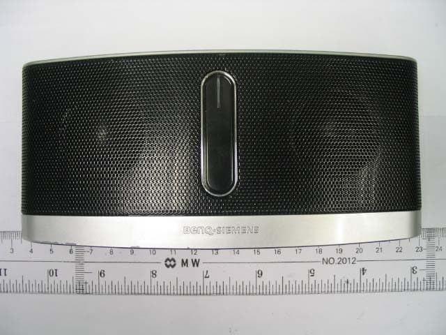
PWX-IMS100
Nov 09, 2006Mobile Sound Set Bluetooth
Equipment Class
DSS - Part 15 Spread Spectrum Transmitter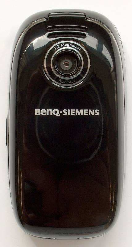
PWX-SL91
Sep 13, 2006GSM 900/1800/1900, UMTS Mobile Phone with BT
Equipment Class
PCE - PCS Licensed Transmitter held to ear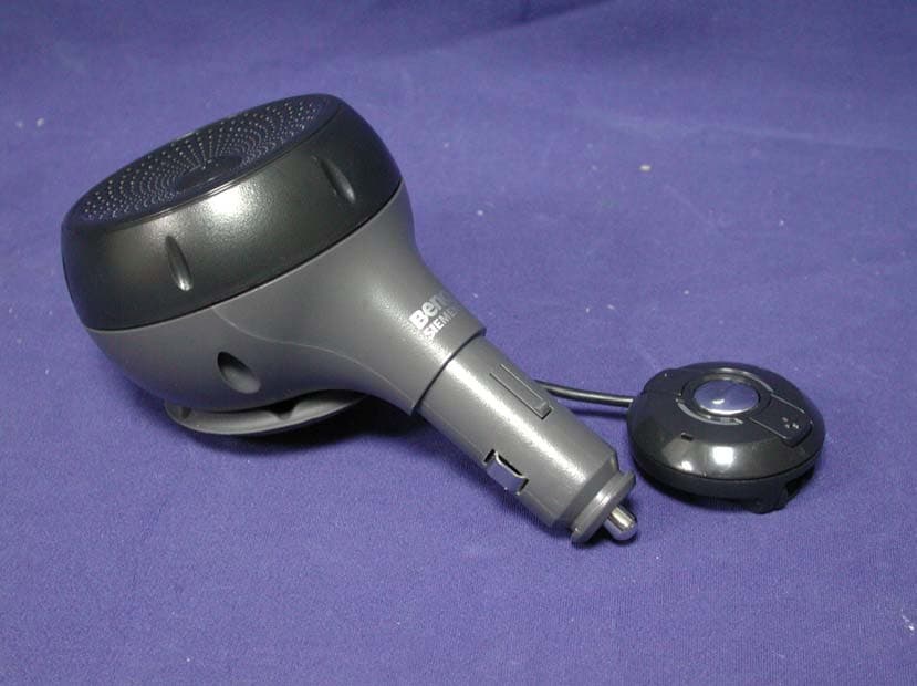
PWX-HKW100
Aug 30, 2006HKW-100 CK Bluetooth Easy
Equipment Class
DSS - Part 15 Spread Spectrum Transmitter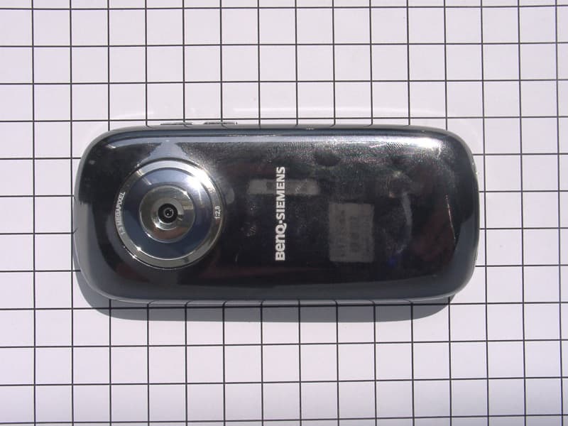
PWX-E71A
Aug 09, 2006GSM 850/1800/1900 Mobile Phone with BT
Equipment Class
DSS - Part 15 Spread Spectrum Transmitter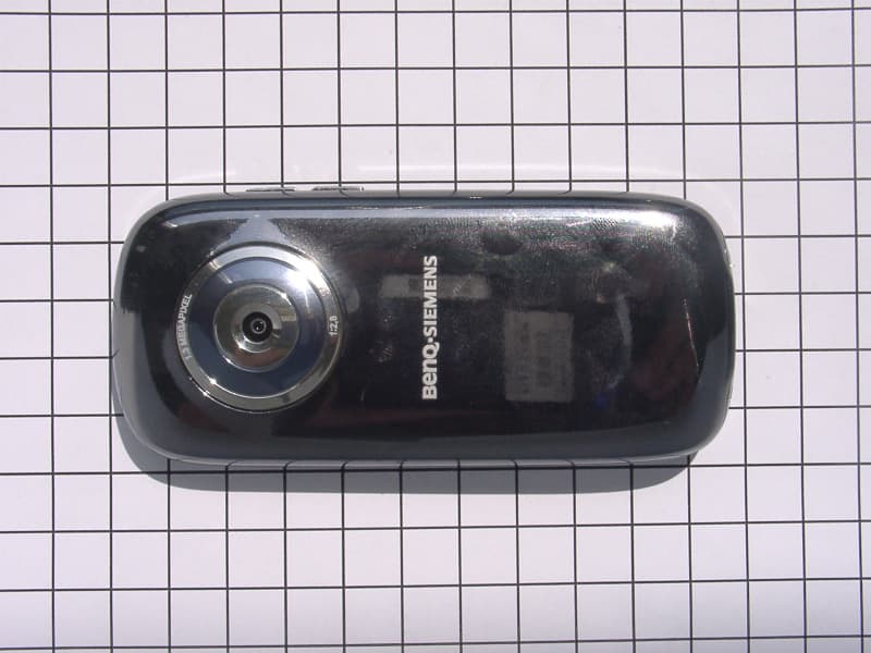
PWX-E71
Aug 09, 2006GSM 900/1800/1900 Mobile Phone with BT and FM Rece
Equipment Class
DSS - Part 15 Spread Spectrum Transmitter