PX8HRU-4300High Power Remote Unit
Comba Telecom Network Systems Limited
Click to zoom
Application Details
- Equipment Class
- B2I - Part 20 Industrial Booster (CMRS)
- Date of Grant
- Jul 30, 2014
- Application Purpose
- Original Equipment
- Date of Application
- Jul 30, 2014
- Equipment Note
- High Power Remote Unit
- Frequency Range
- 2110.00000000 - 2155.00000000
- Country
- China
Documents & Files
Document Text
Text extracted from the exhibit documents filed with the FCC. Open a document above to read the original.
Users Manual
USER MANUAL FOR COMFLEX-4300 D D I I S S T T R R I I B B U U T T E E D D A A N N T T E E N N N N A A S S Y Y S S T T E E M M USER MANUAL ComFlex-4300 QE: 1-0-0 Comba Telecom Ltd. ComFlex-4300 USER MANUAL FOR COMFLEX-4300 The information contained herein is the responsibility of and is approved by the following, to whom all enquiries should be directed in the first instance: This is an unpublished work the copyright in which vests in Comba International ("Comba"). All rights reserved. The information contained herein is confidential and the property of Comba and is supplied without liability for errors or omissions. No part may be reproduced, disclosed or used except as authorised by contract or other written permission. The copyright and the foregoing restriction on reproduction and use extend to all media in which the information may be embodied. USER MANUAL FOR COMFLEX-4300 ENU STATUS : 1-0-0 Copyright - refer to title page Page 3 0.1 CONTENTS Section Page 0.1 CONTENTS ....................................................................................................................................................... 3 0.2 INDEX TO FIGURES AND TABLES ...................................................................................................................... 4 0.3 HISTORY ........................................................................................................................................................... 6 0.4 GLOSSARY OF TERMS ....................................................................................................................................... 7 0.5 SAFETY NOTICES AND ADMONISHMENTS ....................................................................................................... 8 1 GENERAL INFORMATION .............................................................................................................................. 9 2 EQUIPMENT DESCRIPTION .......................................................................................................................... 11 2.1 SYSTEM DIAGRAM ......................................................................................................................................... 11 2.2 TYPICAL APPLICATION ................................................................................................................................... 11 2.3 EQUIPMENT CONSTITUTION ......................................................................................................................... 12 2.4 KIT OF PART ................................................................................................................................................... 13 3 INSTALLATION ............................................................................................................................................ 15 3.1 WARNINGS AND ALERTS ................................................................................................................................ 15 3.2 SITE PLANNING CONSIDERATIONS ................................................................................................................ 16 3.3 INSTALLATION PROCEDURES ......................................................................................................................... 18 3.4 EQUIPMENT CONNECTORS ........................................................................................................................... 26 3.5 EQUIPMENT CONNECTION ............................................................................................................................. 30 4 COMMISSIONING ....................................................................................................................................... 35 4.1 PRE-COMMISSIONING TASKS ........................................................................................................................ 35 4.2 LED INDICATORS ............................................................................................................................................ 35 4.3 DIGITAL DISPLAY INDICATORS ....................................................................................................................... 36 4.3.1 DIGITAL DISPLAY ON RFU .......................................................................................................................... 36 4.3.2 DIGITAL DISPLAY ON FOU.......................................................................................................................... 36 5 WEB GUI ..................................................................................................................................................... 38 5.1 WEB GUI CONNECTION ............................................................................................................................... 38 5.2 WEB GUI INTRODUCTION ........................................................................................................................... 39 5.2.1 [DEVICES] ............................................................................................................................................... 39 5.2.2 [COMMISSIONING] ................................................................................................................................ 44 5.2.3 [FIRMWARE] .......................................................................................................................................... 44 5.2.4 [MANAGEMENT] .................................................................................................................................... 46 5.3 COMMISSIONING PROCEDURE ................................................................................................................... 54 6 ALARMS AND TROUBLESHOOTING ............................................................................................................. 62 6.1 ALARMS .......................................…
Text truncated - open the document above for the full version.
Cover Letter(s)
Stdrebroadcast.1120211Final 1 Inbuilding Radio Rebroadcast Agreement This Inbuilding Radio Rebroadcast Agreement (“Agreement”) is made as of December __, 2013, between Comba Telecom, Inc., a California corporation, with a principal place of business at 235 Charcot, San Jose, CA 95131, (“Permittee”), and Cellco Partnership d/b/a Verizon Wireless, a Delaware general partnership, with a principal place of business at One Verizon Way, Mail Stop 4AW100, Basking Ridge, NJ 07920 (“Permittor”). Background A. Permittee is the tenant at a building at 235 Charcot, San Jose, CA 95131 (the “Premises”), which is located within the geographic area of a license to provide wireless services issued by the Federal Communications Commission (“FCC”) to Permittor, and Permittee desires to purchase and operate an in-building radio distribution system as described in Exhibit A („the System”) to enhance wireless services on the Premises by operating the System on frequencies licensed to Permittor by the FCC. B. The FCC rules applicable to the licenses granted by the FCC require that Permittor control the frequencies which it has been licensed to use, and resolve interference complaints created by the use of those frequencies. Accordingly, Permittor and Permittee agree to permit Permittee‟s System to operate on Permittee‟s FCC licensed frequencies only on the terms and conditions set out in this Agreement. Agreement 1. General. Permittor hereby grants to Permittee, the right to rebroadcast Permittor‟s signal through Permittee‟s System within the Premises. Permittor agrees not to broadcast any other signals, whether FCC licensed or unlicensed, through the System. 2. Operational Requirements. a. Permittee shall own the entire System and be responsible for its physical requirements, inputs (e.g. electrical requirements) and outputs, as well as assuring that the System is maintained, repaired and replaced as needed so as to remain in good operating condition, as defined by Permittor, at all times. Nonetheless, Permittor shall have full control of its FCC licensed frequencies at all times, including full right of access to the System and the right to shut down the System on a 7 day by 24 hour basis. b. Permittee and its vendors/contractors will work with Permittor and its contractors throughout the process of designing, installing, maintaining, adjusting, fixing, modifying and removing the System. Permittee will consult with Permittor on the creation (or, in the case of an existing system, the modification) of the system design and only implement that design after receiving Permittor‟s written approval. Similarly, the Permittee shall not make any other changes to the System without notice to Permittor and Stdrebroadcast.1120211Final 2 obtaining Permittor‟s written approval. The System will only provide coverage in the Premises. c. Should the System cause any radio frequency interference or other problems, or otherwise require repair or replacement, Permittee agrees, and will ensure that, Permittor has the right to require changes, or repair/replacement, to the System, and that such changes will be implemented within 30 days by either Permittee or a contractor determined by Permittee so that the proper quality of signal transmission is maintained. Permittee is responsible for the cost of implementing the changes, repairs or replacements, as needed, unless other arrangements are made and agreed to in writing by Permittor. Permittee acknowledges that this obligation requires it to obtain and assure this right to make changes, repairs and replacements from its contractors/vendors prior to the occurrence of radio interference or other problems or the need for replacement or repair. 3. Term & Termination. a. The term of this Agreement shall be five years with four (4) automatic 5- year renewal terms, unless the Permittor terminates it at the end of the then current term by giving the Permittee written notice of intent to terminate at least six (6) months prior to the end of the then current term. b. Notwithstanding anything to the contrary contained herein, Permittor shall have the right to terminate this Agreement at any time without cause provided that thirty (30) days prior notice is given the Permittee, as Permittor at all times has complete control of its FCC licensed frequencies. c. In the event Permittor defaults in the performance of any of its covenants or obligations hereunder and such default continues for a period of sixty (60) days after written notice thereof from Permittee (unless the nature of the event takes longer to cure and Permittor commences a cure within the time period and diligently pursues it), Permittee may thereafter terminate this Agreement by written notice to Permittee. d. This Agreement may only be terminated in accordance with its terms. Termination of this Agreement shall trigger the parties‟ cessation obligations under Section 4. 4. Cessation. Permittee agrees that the System shall be deemed to be and remain at all times personal property of Permittee and not part of the real estate on which it is located. If Permittee decides to cease using the System, or to vacate the Premises, Permittee agrees to give Permittor 30 days prior written notice that Permittee will stop using Permittor‟s FCC licensed frequencies and decommission the System so that it can no longer use or otherwise benefit from Permittor‟s FCC licensed frequencies. If Permittee vacates the Premises to another location is also within Permittor‟s FCC license area, and Permittee desires to rebroadcast Permittor‟s signal, then Permittor must enter into an Agreement with Permittor like this one regarding such new location prior to placing the System in service. Stdrebroadcast.1120211Final 3 5. Consideration. In consideration for the rights granted herein, Permittee‟s Premises will receive the benefits of enhanced wireless communications arising from operation of the System. 6. Indemnification, Insurance. a. Permittee shall indemnif…
Text truncated - open the document above for the full version.
Cover Letter(s)
Statement MODEL NO.: HRU-4300QP02, HRU-4300QP02A48, HRU-4300QP03, HRU-4300QP03A48 We Comba Telecom Ltd. state that we are selling products HRU-4300QP02, HRU- 4300QP02A48, HRU-4300QP03, HRU-4300QP03A48. While the Antenna System (Antenna, Coupler, etc) is considered by solution provider (Operator, SI, etc), according to site conditions. Authorized Signature: __________________________ Title: Director of Product Marketing International Company: Comba Telecom Ltd. Date: 2014-7-22
External Photos
External Photos
ID Label/Location Info
Statement MODEL NO.: HRU-4300QP02, HRU-4300QP02A48, HRU-4300QP03, HRU-4300QP03A48 We Comba Telecom Ltd. state that the below warning label message will be shown in online, point-of-sale marketing materials and on outside packaging of HRU-4300QP02, HRU- 4300QP02A48, HRU-4300QP03, HRU-4300QP03A48. Warning Label: Authorized Signature: __________________________ Title: Director of Product Marketing International Company: Comba Telecom Ltd. Date: 2014-7-22
ID Label/Location Info
WARNNING LABEL: WARNING! This is NOT a CONSUMER device. It is designed for installation by FCC LICENSEES and QUALIFIED INSTALLERS. You MUST have an FCC LICENSE or express consent of an FCC License to operate this device. Unauthorized use may result in signification forfeiture penalties, including penalties in excess of $100,000 for each continuing violation. HRU-4300 40W AC FCC LABEL: Model No.: HRU01-4300QP02 FCC ID: PX8HRU-4300 This device complies with Part 15 of the FCC Rules. Operation is subject to the following two conditions: (1) This device may not cause harmful interference, and (2) this device must accept any interference received, including interference that may cause undesired operation. Made in China HRU-4300 40W DC FCC LABEL: Model No.: HRU01-4300QP02A48 FCC ID: PX8HRU-4300 This device complies with Part 15 of the FCC Rules. Operation is subject to the following two conditions: (3) This device may not cause harmful interference, and (4) this device must accept any interference received, including interference that may cause undesired operation. Made in China HRU-4300 40W AC LABEL: HRU-4300QP02 High Power Remote Unit S/N: 120140610001 ERP#: 120140610001 Comba Telecom Ltd. HRU-4300 40W DC LABEL: HRU-4300QP02A48 High Power Remote Unit S/N: 120140610001 ERP#: 120140610001 Comba Telecom Ltd. HRU-4300 20W AC FCC LABEL: Model No.: HRU01-4300QP03 FCC ID: PX8HRU-4300 This device complies with Part 15 of the FCC Rules. Operation is subject to the following two conditions: (5) This device may not cause harmful interference, and (6) this device must accept any interference received, including interference that may cause undesired operation. Made in China HRU-4300 20W DC FCC LABEL: Model No.: HRU01-4300QP03A48 FCC ID: PX8HRU-4300 This device complies with Part 15 of the FCC Rules. Operation is subject to the following two conditions: (7) This device may not cause harmful interference, and (8) this device must accept any interference received, including interference that may cause undesired operation. Made in China HRU-4300 20W AC LABEL: HRU-4300QP03 High Power Remote Unit S/N: 120140610001 ERP#: 120140610001 Comba Telecom Ltd. HRU-4300 20W DC LABEL: HRU-4300QP03A48 High Power Remote Unit S/N: 120140610001 ERP#: 120140610001 Comba Telecom Ltd.
Parts List/Tune Up Info
Tune up procedure Page1 DAS System Tune up procedure Index 1 INTRODUCTION .............................................................................................................. 2 2 PREPARATION ................................................................................................................ 2 2.1 PERSONAL PREPARATION ........................................................................................... 2 2.2 EQUIPMENT CONNECTION ........................................................................................... 2 2.2.1 GROUNDING CONNECTION ......................................................................... 2 2.2.2 MU CONNECTION .......................................................................................... 3 2.2.3 HRU CONNECTION ........................................................................................ 3 2.2.4 CHECKLIST BEFORE POWERING ................................................................ 5 2.2.5 VERIFY NORMAL OPRATION........................................................................ 5 3 WEB GUI OPERATION .................................................................................................... 6 3.1 WEB GUI CONNECTION ................................................................................................. 6 3.2 COMMISSIONING PROCEDURE ................................................................................... 7 Tune up procedure Page2 1 INTRODUCTION This document is primarily written for those who are new to Comba ComFlex-4300 DAS system and wish to tune up the equipment. The document is applicable to below products from Comba. Model number: MU-4300, HRU-4300 2 PREPARATION This section will be discussing on: 1 - Preparation for those who are going to operate the equipment; 2 - How to connect to equipment for setting; 3 - LED Indicator description; 2.1 PERSONAL PREPARATION 1 - The following checklist will help to make sure relevant personnel get ready before op- eration. The personnel preparation list: a. Only trained or qualified personnel is recommended for performing tuning with equipment. Operating person should be with necessary knowledge of electronic, RF, and familiar with local regulation, rules. b. Personnel shall read through the manual/instructions/guide carefully before operation. c. Check if there is warning/alert sign on the equipment to avoid possible danger. d. Wear proper cloth. If necessary, equip with PPE (Personal Protective Equipment). e. Before operation, procedures and data recording form should be prepared. 2 - Package inspection Visual inspect the external product package, and check internal items according to pack- ing list. Prepare ample space and easy accessible to socket-outlet. For tools reference please find in manual. 3 - Tools preparation Please prepare tools/cables and measuring instruments ready before hand-on. For tools recommendation, please refer to product user manual. Handling Precautions This covers a range of activities including lifting, lowering, pushing, pulling, carrying, mov- ing, holding or restraining an object, animal or person. It also covers activities that require the use of force or effort, such as pulling a lever, or operating power tools. Caution, Electrostatic Discharge (ESD) Before removing the antistatic bag from repeater, enough caution shall be taken to avoid ESD. The Anti-static Wrist Strap is recommended. 2.2 EQUIPMENT CONNECTION 2.2.1 GROUNDING CONNECTION The equipment must be grounded securely. Connect a copper wire to the grounding terminal on the mounting tab/enclosure, and connect the other end to a protective ground (i.e. building earth point). An internationally acceptable coloring code of the ground connection wire is green/yellow. Tune up procedure Page3 2.2.2 MU CONNECTION Step1: Connect the MU OP (optical) port to one of the HRU OP port. (NOTE: requires Single Mode fiber with SC/APC connectors; MAXIMUM OPTICAL LOSS = 6.5dBo) Step 2: For duplex application, connect the MU TX/RX port to the RF Source (BTS or BDA). For simplex application, connect the MU TX/RX port to the RF Source downlink, and then connect MU RX port with RF Source uplink. Local commissioning & Remote monitoring port BTS AlarmReserved Fiber optic port RF port, to BTS LED indicator Figure 1: Fiber Optical and RF Port Connection Step 3: Connect the power cable to the power supply port (100-240VAC, 1Amp maximum). Power Connection Figure 2: MU Power Connection (Rear Panel) 2.2.3 HRU CONNECTION Step1: Connect the HRU OP (optic) port to one of the OP port located on MU front panel. Step 2: Connect ANT port to a broadband antenna. Step 3: Connect DC 28V port to HRU Power Supply Unit DC 28V port. Step 4: Connect power cable on PSU with the public power grid (110~220VAC, 14Amp maxi- mum). Tune up procedure Page4 1900MHz AWS 850MHz 700MHz LAN RUN ALM COMM SYS_ALM EXT_ALM AUX_1 AUX_2 AUX_3 AUX_4 AUX_5 AUX_6 Computer OCH Antenna Port 1 Antenna Port 2 Antenna Port 3 Antenna Port 4 Grounding Figure 3: HRU Fiber Optical and RF Port Connection Figure 4: PSU Power Port Connection Tune up procedure Page5 2.2.4 CHECKLIST BEFORE POWERING Users MUST check the following items before powering on MU and HRU. Table 1: Check list Item Check List Grounding Make sure MU and HRU are well grounded. Power The utility voltage is within 100~240VAC. DC cable of PSU is well connected with HRU. RF connection RF cables are well connected. Optical connection Optical cables are well connected. The optical link between MU and HRU is normal. VSWR The VSWR of antenna port must less than 1.5. 2.2.5 VERIFY NORMAL OPRATION Verify normal operation upon powering up the equipment. Table 2 MU LED Indications LED Indicator Normal Status Indication PWR Steady green Power indicator. If LED is off, it indicates the system has no power. RUN Flashing green (1 time/sec) MU operation indicator. After initialization (1~2 minutes), the LED should flash at once per sec. If other flashin…
Text truncated - open the document above for the full version.
RF Exposure Info
SGS-CSTC Standards Technical Services Co., Ltd. Application No.: GZEM1405002259RF Page: 1 of 8 FCC ID: PX8HRU-4300 This document is issued by the Company subject to its General Conditions of Service printed overleaf, available on request or accessible at www.sgs.com/terms_and_conditions.htm and, for electronic format documents, subject to Terms and Conditions for Electronic Documents at www.sgs.com/terms_e-document.htm. Attention is drawn to the limitation of liability, indemnification and jurisdiction issues defined therein. Any holder of this document is advised that information contained hereon reflects the Company’s findings at the time of its intervention only and within the limits of Client’s instructions, if any. The Company’s sole responsibility is to its Client and this document does not exonerate parties to a transaction from exercising all their rights and obligations under the transaction documents. This document cannot be reproduced except in full, without prior written approval of the Company. Any unauthorized alteration, forgery or falsification of the content or appearance of this document is unlawful and offenders may be prosecuted to the fullest extent of the law. Unless otherwise stated the results shown in this test report refer only to the sample(s) tested and such sample(s) are retained for 90 days only. RF Exposure Compliance Requirement 1. Standard requirement Systems operating under the provisions of this section shall be operated in a manner that ensures that the public is not exposed to radia frequency energy level in excess limit for maximum permissible exposure. In accordance with 47 CFR FCC Part 2 Subpart J, section 2.1091 this device has been defined as a mobile device whereby a distance of 0.2m normally can be maintained between the user and the device. (a) Limits for Occupational / Controlled Exposure Frequency Range (MHz) Electric Field Strength (E) (V/m) Magnetic Field Strength (H) (A/m) Power Density (S)(mW/cm 2 ) Averaging Times ׀E׀ 2 ׀ ,H׀ 2 or S (minutes) 0.3-3.0 614 1.63 (100)* 6 3.0-30 1842/f 4.89/f (900/f)* 6 30-300 61.4 0.163 1.0 6 300-1500 F/300 6 1500-100000 5 6 (b) Limits for General Population / Uncontrolled Exposure Frequency Range (MHz) Electric Field Strength (E) (V/m) Magnetic Field Strength (H) (A/m) Power Density (S)(mW/cm 2 ) Averaging Times ׀E׀ 2 ׀ ,H׀ 2 or S (minutes) 0.3-1.34 614 1.63 (100)* 30 1.34-30 824/f 2.19/f (180/f)* 30 30-300 27.5 0.073 0.2 30 300-1500 F/500 30 1500-100000 1.0 30 Note: f=frequency in MHz; *Plane-wave equivalent power density SGS-CSTC Standards Technical Services Co., Ltd. Application No.: GZEM1405002259RF Page: 2 of 8 FCC ID: PX8HRU-4300 This document is issued by the Company subject to its General Conditions of Service printed overleaf, available on request or accessible at www.sgs.com/terms_and_conditions.htm and, for electronic format documents, subject to Terms and Conditions for Electronic Documents at www.sgs.com/terms_e-document.htm. Attention is drawn to the limitation of liability, indemnification and jurisdiction issues defined therein. Any holder of this document is advised that information contained hereon reflects the Company’s findings at the time of its intervention only and within the limits of Client’s instructions, if any. The Company’s sole responsibility is to its Client and this document does not exonerate parties to a transaction from exercising all their rights and obligations under the transaction documents. This document cannot be reproduced except in full, without prior written approval of the Company. Any unauthorized alteration, forgery or falsification of the content or appearance of this document is unlawful and offenders may be prosecuted to the fullest extent of the law. Unless otherwise stated the results shown in this test report refer only to the sample(s) tested and such sample(s) are retained for 90 days only. 2. MPE Calculation Method S (mW/cm 2 )=P*G/4Pi*R 2 S= Power Density (mW/cm 2 ) P=Peak RF conducted output Power (mW) G=EUT Antenna numeric gain (numeric) R= Separation distance between radiator and human body (cm); R= SPiGP*4/)*( From the maximum EUT RF output power, as well as the gain of the used antenna, according to the RF power density limit above, the minimum distance between the antenna and human body will be calculated. 3. Calculated Result 3.1 For downlink: 728MHz to 757MHz 1)For Maximum output power 40W: Frequency (MHz) F Maximum Antenna Gain (dBi) Maximum Antenna Gain (Numeric) Peak Output Power (dBm) Peak Output Power (mW) Limit of Power Density (S) (mW/cm 2 ) Minimum Distance to human body (cm) Lowest 12.5 17.8 46.4 43651.5832 2.443 159.1305 Middle 12.5 17.8 46.1 40738.0277 2.475 152.7311 Highest 12.5 17.8 46.2 41686.9383 2.507 153.5105 2)For Maximum output power 20W: Frequency (MHz) F Maximum Antenna Gain (dBi) Maximum Antenna Gain (Numeric) Peak Output Power (dBm) Peak Output Power (mW) Limit of Power Density (S) (mW/cm 2 ) Minimum Distance to human body (cm) Lowest 12.5 17.8 43.2 20892.9613 2.443 110.0914 Middle 12.5 17.8 43.1 20417.3794 2.475 108.1254 Highest 12.5 17.8 43.3 21379.6209 2.507 109.9355 SGS-CSTC Standards Technical Services Co., Ltd. Application No.: GZEM1405002259RF Page: 3 of 8 FCC ID: PX8HRU-4300 This document is issued by the Company subject to its General Conditions of Service printed overleaf, available on request or accessible at www.sgs.com/terms_and_conditions.htm and, for electronic format documents, subject to Terms and Conditions for Electronic Documents at www.sgs.com/terms_e-document.htm. Attention is drawn to the limitation of liability, indemnification and jurisdiction issues defined therein. Any holder of this document is advised that information contained hereon reflects the Company’s findings at the time of its intervention only and within the limits of Client’s instructions, if any. The Company’s sole responsibility is to its Client and this document does not exonerate parties to a transaction from exercising all th…
Text truncated - open the document above for the full version.
Test Report
SGS-CSTC Standards Technical Services Co., Ltd. Report No.: GZEM140500225901 Page: 56 of 132 This document is issued by the Company subject to its General Conditions of Service printed overleaf, available on request or accessible at www.sgs.com/terms_and_conditions.htm and, for electronic format documents, subject to Terms and Conditions for Electronic Documents at www.sgs.com/terms_e-document.htm. Attention is drawn to the limitation of liability, indemnification and jurisdiction issues defined therein. Any holder of this document is advised that information contained hereon reflects the Company’s findings at the time of its intervention only and within the limits of Client’s instructions, if any. The Company’s sole responsibility is to its Client and this document does not exonerate parties to a transaction from exercising all their rights and obligations under the transaction documents. This document cannot be reproduced except in full, without prior written approval of the Company. Any unauthorized alteration, forgery or falsification of the content or appearance of this document is unlawful and offenders may be prosecuted to the fullest extent of the law. Unless otherwise stated the results shown in this test report refer only to the sample(s) tested and such sample(s) are retained for 90 days only. 2.4 LTE Mode: 2.4.1 one signal input —Lower Edge 2.4.2 one signal input — Upper Edge SGS-CSTC Standards Technical Services Co., Ltd. Report No.: GZEM140500225901 Page: 57 of 132 This document is issued by the Company subject to its General Conditions of Service printed overleaf, available on request or accessible at www.sgs.com/terms_and_conditions.htm and, for electronic format documents, subject to Terms and Conditions for Electronic Documents at www.sgs.com/terms_e-document.htm. Attention is drawn to the limitation of liability, indemnification and jurisdiction issues defined therein. Any holder of this document is advised that information contained hereon reflects the Company’s findings at the time of its intervention only and within the limits of Client’s instructions, if any. The Company’s sole responsibility is to its Client and this document does not exonerate parties to a transaction from exercising all their rights and obligations under the transaction documents. This document cannot be reproduced except in full, without prior written approval of the Company. Any unauthorized alteration, forgery or falsification of the content or appearance of this document is unlawful and offenders may be prosecuted to the fullest extent of the law. Unless otherwise stated the results shown in this test report refer only to the sample(s) tested and such sample(s) are retained for 90 days only. 2.4.3 two signal input —Lower…
Text truncated - open the document above for the full version.
Contact Information
Applicant
Ronin Gong(Director)
Test Firm
SGS-CSTC Standards Technical Services Co., LtdJerry Chan
Technical Specifications
| # | Rule Parts | Frequency Range | Power Output | Emission | Tolerance |
|---|---|---|---|---|---|
| 9 | 27 | 2.11 GHz - 2.15 GHz | 43.651 W | G7D | Amp |
Other Applications from Comba Telecom Network Systems Limited

PX8-SW-J
Jan 01, 2025SailaJoint
Equipment Class
DTS - Digital Transmission System
PX8RX14V3-A
Dec 08, 2024Public Safety UHF and VHF Dualband Bi-Directional Amplifier
Equipment Class
B9A - Part 90 Class A Industrial Booster (non-SMR)
PX8CFNG-MU
May 18, 2023Comflex NG
Equipment Class
B2I - Part 20 Industrial Booster (CMRS)
PX8MIRCU-S24
May 27, 2021Multi internal Remote Control Unit
Equipment Class
JAB - Part 15 Class B Digital Device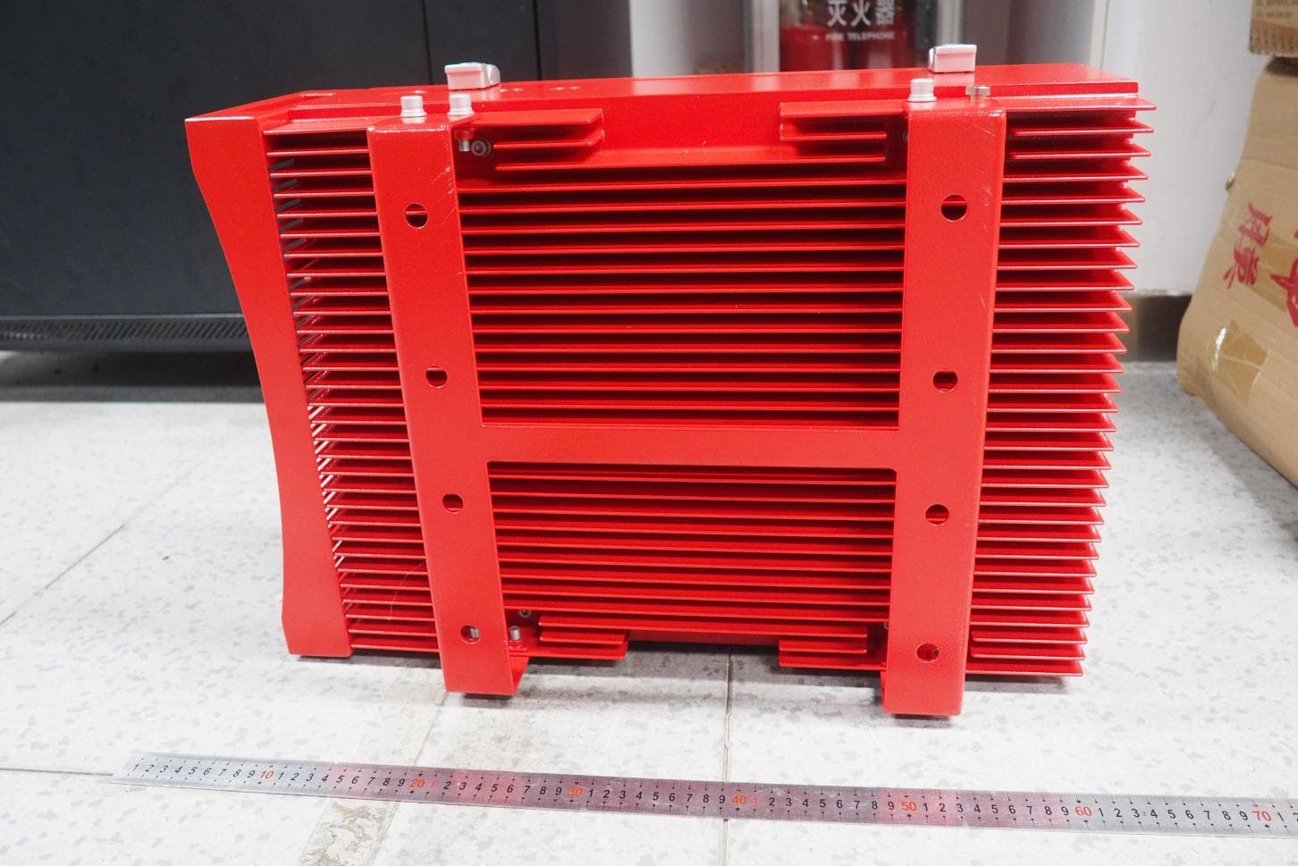
PX8RXB37
Jul 20, 2020700MHz/800MHz Public Safety Bi-directional Amplifier
Equipment Class
B9B - Part 90 Class B Industrial Booster (non-SMR)