PX8RA-5700-RTri-band Distributed Antenna System
Comba Telecom Network Systems Limited
Click to zoom
Application Details
- Equipment Class
- AMP - Amplifier
- Date of Grant
- May 09, 2011
- Application Purpose
- Original Equipment
- Date of Application
- Apr 30, 2011
- Equipment Note
- Tri-band Distributed Antenna System
- Frequency Range
- 748.00000000 - 754.00000000
- Country
- China
Documents & Files
Document Text
Text extracted from the exhibit documents filed with the FCC. Open a document above to read the original.
Users Manual
USER MANUAL FOR RA-5700 RA-5700 QI Copyright - refer to title page Page 1 ENU Status : 1-1-2 USER MANUAL The information contained herein is the responsibility of and is approved by the following, to whom all enquiries should be directed in the first instance: Comba Telecom Ltd. This is an unpublished work the copyright in which vests in Comba International ("Comba"). All rights reserved. The information contained herein is confidential and the property of Comba and is supplied without liability for errors or omissions. No part may be reproduced, disclosed or used except as authorised by contract or other written permission. The copyright and the foregoing restriction on reproduction and use extend to all media in which the information may be embodied. RA-5700 TRI-BAND DISTRIBUTED ANTENNA SYSTEM USER MANUAL FOR RA-5700 RA-5700 QI Copyright - refer to title page Page 2 ENU Status : 1-1-2 0.2 CONTENTS Section Page 0.2 CONTENTS ........................................................................................................................... 2 0.3 INDEX TO FIGURES AND TABLES ..................................................................................... 4 0.4 HISTORY ............................................................................................................................... 6 0.5 GLOSSARY OF TERMS ....................................................................................................... 7 0.6 FCC SAFETY COMPLIANCE ................................................................................................ 8 0.7 SAFETY NOTICES AND ADMONISHMENTS .................................................................... 10 1 GENERAL INFORMATION ................................................................................................. 11 2 EQUIPMENT DESCRIPTION .............................................................................................. 13 2.1 SYSTEM DIAGRAM ............................................................................................................ 13 2.2 TYPICAL APPLICATION ..................................................................................................... 14 2.2.1 SINGLE FIBER CONFIGURATION ..................................................................................... 14 2.3 EQUIPMENT LAYOUT ........................................................................................................ 15 2.4 EQUIPMENT CONSTITUTION ........................................................................................... 17 2.5 KIT OF PARTS .................................................................................................................... 18 3 INSTALLATION ................................................................................................................... 19 3.1 WARNINGS AND ALERTS ................................................................................................. 19 3.2 SITE PLANNING CONSIDERATIONS ................................................................................ 20 3.2.1 SYSTEM INSTALLATION CHECKLIST .............................................................................. 21 3.3 INSTALLATION PROCEDURES ......................................................................................... 22 3.3.1 GOODS INWARDS INSPECTION ...................................................................................... 22 3.3.2 TOOLS ................................................................................................................................. 22 3.3.3 PREPARATION ................................................................................................................... 22 3.3.4 CABINET MOUNTING OF MU ............................................................................................ 23 3.3.5 RU MOUNTING RACK DIMENSION .................................................................................. 23 3.3.6 WALL MOUNTING OF RU .................................................................................................. 24 3.3.7 POLE MOUNTING OF RU .................................................................................................. 25 3.3.8 DRIP-LOOP ......................................................................................................................... 25 3.4 EQUIPMENT CONNECTORS ............................................................................................. 26 3.4.1 MU CONNECTORS............................................................................................................. 26 3.4.2 RU CONNECTORS ............................................................................................................. 27 3.5 EQUIPMENT CONNECTION .............................................................................................. 28 3.5.1 GROUNDING CONNECTION ............................................................................................. 28 3.5.2 LI-ION BATTERY CONNECTION ....................................................................................... 28 3.5.3 OPTICAL CONNECTION .................................................................................................... 28 3.5.4 EXTERNAL ALARM CONNECTION ................................................................................... 30 3.5.5 BTS ALARM CONNECTION ............................................................................................... 31 3.5.6 CONNECT TO PC ............................................................................................................... 32 4 COMMISSIONING ............................................................................................................... 33 4.1 PRE-COMMISSIONING TASKS ......................................................................................... 33 4.2 MU/RU RESET TIME DURATION ...................................................................................... 33…
Text truncated - open the document above for the full version.
Block Diagram
Block Diagram Optical input and output port RF input and output port RF input and output port DL RF output power UL RF input power RF Amplifier Unit: BLF6G20-45 and MW6S010GNR1 Supply voltage: 28V Supply Current: 0.36A and 0.125A
External Photos
External photos Remoter unit of RA-5700 system Enclosure of Remote Unit I/O port of Remote Unit
Operational Description
PX8RA-5700-R Operation Description The RA-5700-R is Remote Unit of Multi-band Distributed Antenna System RA-5700, which is an RF over fiber solution that can enhance a wireless network’s coverage by extending cellular services from existing cell sites for both indoor and outdoor applications. The Remote Unit (RU) is modular designed up to support 3 independent inputs, for example 700MHz, 850MHz and 1900MHz. It is modular designed so that each unit can accommodate up to 3 independent bands. On the DL, combined signals as 700MHz, 850MHz and 1900MHz from the BTSs converted into optical signals after amplification in the MU. Then the optical signals are transmitted to the RU via optical fiber. The Optical TX/RX Module of RU converts the DL optical signals into RF signals. After amplification, the signals are transmitted at the MT port to the service antenna. On the UL, the signals transmitted by the mobile are converted into optical signals, and then via the UL optical fiber. PX8RA-5700-R is Remote unit of RA-5700 system The Downlink RF output power, gain, maximum input power, supply power are list in the following table.
Parts List/Tune Up Info
Issued by WHGZ Date 11-02-11 Checked by DLGZ Document Id WE-TN-10022-005 Title RA-5700 Tune Up Procedures Project No WE-TN-10022 Revision R1A Page 1 / 23 All rights reserved and property of Comba RA-5700 Tune up Procedures Index 1 EQUIPEMENT CONNECTION ............................................................................................... 2 1.1 GOUNDING CONNECTION ............................................................................................ 2 1.2 LI-ION BATTERY CONNECTION .................................................................................... 2 1.3 OPTICAL CONNECTION ................................................................................................. 3 1.4 EXTERNAL ALARM CONNECTION ................................................................................ 4 1.5 BTS ALARM CONNECTION ............................................................................................ 5 1.6 CONNECT TO PC ............................................................................................................ 5 2 LED INDICATORS .................................................................................................................. 6 2.1 MU LED INDICATORS ..................................................................................................... 6 2.2 RU LED INDICATORS ..................................................................................................... 6 3 WEB OMT ............................................................................................................................... 7 3.1 CONNECTION FROM PC TO EQUIPMENT ................................................................... 7 3.2 OMT CONFIGURATION .................................................................................................. 8 3.2.1 SYSTEM INFORAMTION ......................................................................................... 8 3.2.2 RF INFORMATION ................................................................................................. 11 3.2.3 ALARM INFORMATION ......................................................................................... 15 3.2.4 PROPERTIES INFORMATION .............................................................................. 16 3.2.5 USER MANAGEMENT ........................................................................................... 19 3.2.6 HELP ....................................................................................................................... 20 3.3 CHANGE PASSWORD .................................................................................................. 20 4 TROUBLE SHOOTING ......................................................................................................... 22 Revision History Revision Date Author Remarks P1A 11Feb11 WHGZ Prepared by SXGZ R1A 11Feb11 WHGZ Checked by DLGZ Issued by WHGZ Date 11-02-11 Checked by DLGZ Document Id WE-TN-10022-005 Title RA-5700 Tune Up Procedures Project No WE-TN-10022 Revision R1A Page 2 / 23 All rights reserved and property of Comba 1 EQUIPEMENT CONNECTION 1.1 GOUNDING CONNECTION Ground connection To ensure safe operation of the product, a ground (earth) connection is required. For single phase AC power source, the product must be grounded by connecting the “earth wire” of the power cord to the ground terminal of the AC supply. For operating this product with DC power system (such as rectifiers), the product should not be connected to power systems that switch open the return lead because the return lead could function as the ground (earth) connection for the equipment. Protective Ground Connection The enclosure must be grounded securely by connecting a copper wire (CSA 16mm 2 ) to the grounding terminal on the equipment/rack, and the other end to a protective ground (i.e. building earth point). An internationally acceptable colour code of the ground connection wire is green/yellow. Such a ground connection implements the “Protective Ground Connection”, and must be connected to the equipment at the designated ground point. In general, do not connect the supply before establishing an adequate ground (earth) connection. MU Grounding Connection Connect the grounding terminal located on the back panel of MU to a protective ground (i.e. building earth point). RU Grounding Connection The equipment must be grounded securely. Connect a copper wire to the grounding terminal on the mounting tab/enclosure, and connect the other end to a protective ground (i.e. building earth point). An internationally acceptable coloring code of the ground connection wire is green/yellow. 1.2 LI-ION BATTERY CONNECTION Li-ion battery is provided with this system to ensure power is supplied to the system monitoring unit and MCU and to ensure the alarm message could be sent to OMC effectively in case of mains power failure. Caution: Be careful of the risk of explosion if battery is replaced by an incorrect type. Dispose of used batteries according to the instructions. Issued by WHGZ Date 11-02-11 Checked by DLGZ Document Id WE-TN-10022-005 Title RA-5700 Tune Up Procedures Project No WE-TN-10022 Revision R1A Page 3 / 23 All rights reserved and property of Comba 1.3 OPTICAL CONNECTION MU is connected to RU via optical fiber (length<13km). Connect MU front panel‟s OP1-OP4 with RU‟s OP OUT/IN (via an optical jumper) respectively. Refer to the following connection: EXT_ALM OMT BTS_ALM MODEMOP1OP2OP3OP4 RUN ALMMODPWR OP1 OP2OP4OP3 AWS 1900MHz850MHz 700MHz 100-240V~50/60Hz ANT 700 TX_EXT RX_EXT 850+1900 ANT EXT_ALMOP OUT/IN OMT Figure 1: Optical Connection Issued by WHGZ Date 11-02-11 Checked by DLGZ Document Id WE-TN-10022-005 Title RA-5700 Tune Up Procedures Project No WE-TN-10022 Revision R1A Page 4 / 23 All rights reserved and property of Comba 1.4 EXTERNAL ALARM CONNECTION For MU, this is a DB9 connector. The following figure and table show the pin allocation and definition. Pin numbering are shown lookin…
Text truncated - open the document above for the full version.
RF Exposure Info
ATTACHMENT FCC ID: PX8RA-5700-R ** MPE Calculations ** Environmental evaluation and exposure limit according to FCC CFR 47part 1, §1.1307, §1.1310 The calculation was done for required safe distance. Limits for General Population/Uncontrolled Exposure Note. This MPE calculation is worst case: 1. 700MHz and 850 frequency band Maximum permissible exposure is Freq. (MHz)/1500 = MPE mW/cm 2 Freq = 733 MHz, 733/1500 = 0.488 mW/cm 2 2. 1900MHz band: The maximum permissible power density is =1 mW/ cm 2 Max Tx output power at antenna input = 30 dBm = 1000 mW Maximum Antenna Gain = 6 dBi, so the numeric gain = 4 (dBi) The maximum RF power from Antenna = 36 dBm (EIRP) = 4000 mW (EIRP) MPE Calculation at worst case: Estimated safe separation: R = √(PG / (4π* 0.488)) R = √(1000 * 4 / (4π*0.488)) R = 25.55 cm Where, P = Power input to the antenna (mW) G = Numeric power gain of the antenna R = Distance to the center of the radiation of the antenna (20cm = limit for MPE) The minimum safe distance for Occupational/Controlled exposure is 25.55cm for the antenna when installed. This is the worst case for the downlink. The maximum antenna gain stated is for the downlink. This product is installed by trained professionals in outdoor applications only
Test Report
Produkte Products Prüfbericht - Nr.: Test Report No.: 16026515 001 Seite 2 von 66 Page 2 of 66 TEST SUMMARY EUT: RA-5700-R Mode Test items Result Transmitter Requirements RF power Output Pass Occupied Bandwidth, Input/Output Comparison Pass Spurious Emissions at antenna terminal Pass Field Strength of Spurious Radiation Pass Frequency Stability Pass LTE Error Vector Magnitude (EVM) No limit RF Power Output Pass Occupied Bandwidth, Input/Output Comparison Pass Out-of-Band Emissions at antenna terminal Pass Intermodulation Test Pass Field Strength of Spurious Radiation Pass Out of Band Rejection Pass Frequency Stability Pass CDMA Error Vector Magnitude (EVM) No limit Note: as the DUT is only RF amplifier without phase modulation function, the Error Vector Magnitude (EVM) is not necessary for FCC application, it is only client’s additional request for verification. Produkte Products Prüfbericht - Nr.: Test Report No.: 16026515 001 Seite 3 von 66 Page 3 of 66 Contents 1 GENERAL REMARKS................................................................................................................ 5 1.1 COMPLEMENTARY MATERIALS................................................................................................ 5 2 TEST SITES.............................................................................................................................. 5 2.1 TEST FACILITIES...................................................................................................................... 5 2.2 LIST OF TEST AND MEASUREMENT INSTRUMENTS................................................................. 6 2.3 TRACE ABILITY......................................................................................................................... 7 2.4 CALIBRATION........................................................................................................................... 7 2.5 MEASUREMENT UNCERTAINTY................................................................................................ 7 2.6 LOCATION OF ORIGINAL DATA................................................................................................. 7 2.7 STATUS OF FACILITY USED FOR TESTING................................................................................ 7 3 GENERAL PRODUCT INFORMATION......................................................................................... 8 3.1 PRODUCT FUNCTION AND INTENDED USE............................................................................... 9 3.2 RATINGS AND SYSTEM DETAILS.............................................................................................. 9 3.3 INDEPENDENT OPERATION MODES....................................................................................... 10 3.4 SUBMITTED DOCUMENTS....................................................................................................... 10 4 TEST SET-UP AND OPERATION MODE................................................................................... 11 4.1 PRINCIPLE OF CONFIGURATION SELECTION......................................................................... 11 4.2 TEST OPERATION AND TEST SOFTWARE.............................................................................. 11 4.3 SPECIAL ACCESSORIES AND AUXILIARY EQUIPMENT.......................................................... 11 4.4 COUNTERMEASURES TO ACHIEVE EMC COMPLIANCE......................................................... 11 4.5 TEST SET-UP.......................................................................................................................... 12 4.6 TEST FREQUENCY SELECTION............................................................................................... 13 5 TEST RESULTS....................................................................................................................... 14 5.1 TEST RESULT OF LTE 700MHZ BAND 1 AND BAND 2..................................................... 14 5.1.1 RF power Output....................................................................................................................................14 5.1.2 Occupied bandwidth, Input/output Comparison................................................................................16 5.1.3 Spurious Radiation at antenna terminal.............................................................................................20 5.1.4 Field Strength of Spurious Emissions.................................................................................................30 5.1.5 Frequency Stability................................................................................................................................33 5.1.6 Error Vector Magnitude (EVM)............................................................................................................35 5.2 TEST RESULT OF CDMA 850 AND CDMA 1900................................................................. 37 5.2.1 RF power Output....................................................................................................................................37 5.2.2 Occupied bandwidth, Input/output Comparison................................................................................39 Produkte Products Prüfbericht - Nr.: Test Report No.: 16026515 001 Seite 4 von 66 Page 4 of 66 5.2.3 Out-of-Band Emissions at antenna terminal......................................................................................43 5.2.4 Intermodulation.......................................................................................................................................48 5.2.5 Field Strength of Spurious Emissions.................................................................................................51 5.2.6 Out-of-Band Rejection...........................................................................................................................54 5.2.7 Frequency Stability...................................…
Text truncated - open the document above for the full version.
Test Setup Photos
Produkte Products Prüfbericht - Nr.: Test Report No.: 16026515 001 Seite 63 von 66 Page 63 of 66 6 Photographs of the Test Set-Up Photograph 1: Set-up for RF power, Occupied Bandwidth, Out-of-Band emissions, Intermodulation test, Spurious Emissions at antenna terminal, EVM Produkte Products Prüfbericht - Nr.: Test Report No.: 16026515 001 Seite 64 von 66 Page 64 of 66 Photograph 2: Set-up for Radiation Measurement Below 1GHz Produkte Products Prüfbericht - Nr.: Test Report No.: 16026515 001 Seite 65 von 66 Page 65 of 66 Photograph 3: Set-up for Radiation Measurement above 1GHz 1 GHz to 18 GHz 18 GHz to 20 GHz
Contact Information
Applicant
Ronin Gong(Director)
Technical Contact
TUV Rheinland (Guangdong) Ltd.Liangdong Xie
[email protected]86 020 2839 1888
Building H, No11, Caipin Road, · Guangzhou · China
Test Firm
TUV Rheinland (GuangDong) Ltd.Yuxin Huang
Technical Specifications
| # | Rule Parts | Frequency Range | Power Output | Emission | Tolerance |
|---|---|---|---|---|---|
| 4 | 27 | 748 MHz - 754 MHz | 1.02 W | F9W | Amp |
Other Applications from Comba Telecom Network Systems Limited

PX8-SW-J
Jan 01, 2025SailaJoint
Equipment Class
DTS - Digital Transmission System
PX8RX14V3-A
Dec 08, 2024Public Safety UHF and VHF Dualband Bi-Directional Amplifier
Equipment Class
B9A - Part 90 Class A Industrial Booster (non-SMR)
PX8CFNG-MU
May 18, 2023Comflex NG
Equipment Class
B2I - Part 20 Industrial Booster (CMRS)
PX8MIRCU-S24
May 27, 2021Multi internal Remote Control Unit
Equipment Class
JAB - Part 15 Class B Digital Device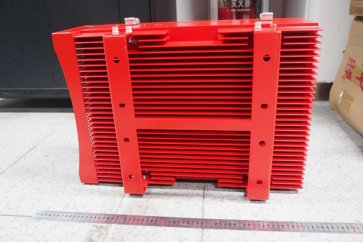
PX8RXB37
Jul 20, 2020700MHz/800MHz Public Safety Bi-directional Amplifier
Equipment Class
B9B - Part 90 Class B Industrial Booster (non-SMR)