PX8RXA37700MHz/800MHz Public Safety Bi-directional Amplifier
Comba Telecom Network Systems Limited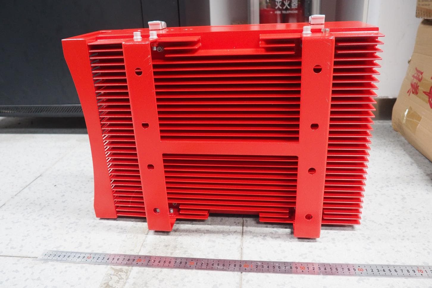
Click to zoom
Application Details
- Equipment Class
- B9A - Part 90 Class A Industrial Booster (non-SMR)
- Date of Grant
- Jul 20, 2020
- Application Purpose
- Original Equipment
- Date of Application
- Jul 20, 2020
- Equipment Note
- 700MHz/800MHz Public Safety Bi-directional Amplifier
- Frequency Range
- 769.00000000 - 775.00000000
- Country
- China
Documents & Files
Document Text
Text extracted from the exhibit documents filed with the FCC. Open a document above to read the original.
Users Manual
RXA3748/RXA3792 RXB3748/RXB3792 QE: 1-0-0 编 制: _ _ _ 审 核: __ 会 签: _ _ 标准化: _ 批 准: _ 京信通信系统(中国)有限公司 CriticalPoint Public Safety BDA DIGITAL BAND SELECTIVE REPEATER USER MANUAL CriticalPoint PUBLIC SAFETY BI- DIRECTIONAL AMPLIFIER USER MANUAL RXA3748/RXA3792 RXB3748/RXB3792 QE: 1-0-0 Comba Telecom Ltd. ENU STATUS : 1-0-0 Copyright - refer to title page Page 3 INSTALLATION GUIDE FOR RX-7W22, II2 The information contained herein is the responsibility of and is approved by the following, to whom all enquiries should be directed: This is an unpublished work the copyright in which vests in Comba International ("Comba"). All rights reserved. The information contained herein is confidential and the property of Comba and is supplied without liability for errors or omissions. No part may be reproduced, disclosed or used except as authorized by contract or other written permission. The copyright and the foregoing restriction on reproduction and use extend to all media in which the information may be embodied. ENU STATUS : 1-0-0 Copyright - refer to title page Page 4 INSTALLATION GUIDE FOR RX-7W22, II2 0.1 CONTENTS Section Page 1.1 CONTENTS ....................................................................................................................................... 4 1.2 INDEX TO FIGURES AND TABLES ............................................................................................. 6 1.3 HISTORY ........................................................................................................................................... 7 1.4 GLOSSARY OF TERMS ................................................................................................................. 8 1.5 SAFETY NOTICES AND ADMONISHMENTS............................................................................. 9 1 GENERAL INFORMATION ........................................................................................................... 10 2 EQUIPMENT DESCRIPTION ....................................................................................................... 14 2.1 FUNCTIONAL BLOCK DIAGRAM ............................................................................................... 14 2.2 EQUIPMENT LAYOUT .................................................................................................................. 15 2.3 EQUIPMENT CONSTITUTION .................................................................................................... 16 3 INSTALLATION .............................................................................................................................. 17 3.1 WARNINGS AND ALERTS ........................................................................................................... 17 3.2 SITE PLANNING CONSIDERATIONS ....................................................................................... 18 3.2.1 SITE PLANNING ............................................................................................................................ 18 3.2.2 INSTALLATION CHECKLIST ....................................................................................................... 19 3.3 INSTALLATION PROCEDURES ................................................................................................. 20 3.3.1 GOODS INWARDS INSPECTION ............................................................................................... 20 3.3.2 TOOLS ............................................................................................................................................. 20 3.3.3 PREPARATION .............................................................................................................................. 20 3.3.4 WALL MOUNTING ......................................................................................................................... 21 3.3.5 DRIP-LOOP ..................................................................................................................................... 21 3.4 EQUIPMENT CONNECTORS...................................................................................................... 22 3.4.1 PS BDA CONNECTORS ............................................................................................................... 22 3.4.2 PS BDA LED INDICATORS .......................................................................................................... 23 3.4.3 GROUNDING CONNECTION ...................................................................................................... 23 3.4.4 RF CABLE CONNECTION ........................................................................................................... 23 3.4.5 ETHERNET CONNECTION ......................................................................................................... 23 3.4.6 DRY CONTACT CABLE CONNECTION .................................................................................... 24 4 COMMISSIONING ......................................................................................................................... 25 4.1 PRE-COMMISSIONING TASKS .................................................................................................. 25 4.2 COMMISSIONING PROCEDURE ............................................................................................... 26 5 WEB GUI ......................................................................................................................................... 28 5.1 WEB GUI CONNECTION ............................................................................................................. 28 5.2 WEB GUI INTRODUCTION .......................................................................................................... 29 5.2.1 [HOME] ............................................................................................................................................ 29 5.2.2 [COMMISSIONING] ..................................…
Text truncated - open the document above for the full version.
Attestation Statements
Comba Telecom Ltd. To: SGS North America Inc. 620 Old Peachtree Road SUITE 100 Suwanee, Georgia United States From: Comba Telecom Ltd. 611 East Wing, No. 8 Science Park West Avenue, Hk HongKong, 510663, China Regarding: Confidentiality Request regarding application for FCC ID: PX8RXA37; PX8RXB37; According to FCC KDB 935210 D02 Signal Boosters Certification v04r02 section V (g) requirement: (g) Attestation (must be non-confidential exhibit, signed by the applicant; signature by test lab, agent, or TCB is not acceptable) should include: (1) Warning label messages and Class A/B disclosure will be also shown in online and point-of-sale marketing materials and on outside packaging of device: we Comba telecom Ltd declared our Warning label messages and Class A/B disclosure will be also shown in online and point-of-sale marketing materials and on outside packaging of device. for FCC ID: PX8RXA37; THIS IS A 90.219 CLASS A DEVICE. WARNING. This is NOT a CONSUMER device. It is designed for installation by FCC LICENSEES and QUALIFIED INSTALLERS. You MUST have an FCC LICENSE or express consent of an FCC Licensee to operate this device. The PS BDA can be configured as Class A ( FCC ID: PX8RXA37) Signal Booster. You MUST register Class B signal boosters (as defined in 47 CFR 90.219) online at www.fcc.gov/signal-boosters/registration. Unauthorized use may result in significant forfeiture penalties, including penalties in excess of $100,000 for each continuing violation. for FCC ID: PX8RXB37; THIS IS A 90.219 CLASS B DEVICE. WARNING. This is NOT a CONSUMER device. It is designed for installation by FCC LICENSEES and QUALIFIED INSTALLERS. You MUST have an FCC LICENSE or express consent of an FCC Licensee to operate this device. The PS BDA can be configured as Class B (FCC ID: PX8RXB37) Signal Booster. You MUST register Class B signal boosters (as defined in 47 CFR 90.219) online at www.fcc.gov/signal-boosters/registration. Unauthorized use may result in significant forfeiture penalties, including penalties in excess of $100,000 for each continuing violation. Sincerely,
Cover Letter(s)
FCC ID:PX8RXA37
Cover Letter(s)
Applicant Declaration Applicant Declaration Rev:0.0 SGS North America Inc. 620 Old Peachtree Road SUITE 100 Suwanee, Georgia 30024 United States Applicant Legal Business Name Comba Telecom Ltd. Address 611 East Wing, No. 8 Science Park West Avenue, Hk, 510663, China Grantee Code PX8 FCC ID PX8RXA37 Authorized Contact Name Ronin Gong Contact Email - Contact Phone 822225788 I, the undersigned, certify that I am an authorized signatory for the Applicant and therefore declare; a) in accordance with 47CFR2.911(d), all of the statements herein and the exhibits attached hereto are true and correct to the best of my knowledge and belief. b) in accepting a Grant of Equipment Authorization issued by a TCB, under the authority of the FCC, as a result of the representations made in this application, the Applicant is responsible for: (1) labeling the equipment with the exact FCC ID as specified in this application, (2) compliance statement labeling pursuant to the applicable rules, (3) compliance of the equipment with the applicable technical rules, c) if the Applicant is not the actual manufacturer of the equipment, appropriate arrangements have been made with the manufacturer to ensure that production units of this equipment will continue to comply with the FCC’s technical requirements. d) in accordance with 47 CFR 2.909 and KDB394321, the Applicant has read, understood and agrees to accept that they are the responsible party and agree to abide by their responsibilities as specified under 47 CFR 2.909 and KDB394321. e) in accordance with ISO17065, FCC KDB641163, FCC KDB610077, KDB394321 and RSP-100, the Applicant has read, understood, accepts and agrees to abide by the post market surveillance requirements. (1) the Applicant understands, accepts and agrees that a sample may be requested for surveillance testing. (2) the Applicant shall make provisions to always have a production sample available upon request by SGS, FCC and/or ISED. (3) the Applicant shall, upon request by SGS, at the Applicant’s expense, provide a production sample of the requested product to SGS, FCC and/or ISED as instructed. The sample shall include all support devices, cables, software, accessories or other hardware or software required for evaluation, review, certification and audit surveillance of products certified by SGS. f) neither the Applicant nor any party to the application is subject to a denial of Federal benefits, that includes FCC benefits, pursuant to Section 5301 of the Anti-Drug Abuse Act of 1988, 21 U.S.C. §862 because of a conviction for possession or distribution of a controlled substance. See 47CFR 1.2002(b) for the definition of a “party” for these purposes. g) the Applicant has read, understood, accepts and agrees to abide by the SGS North America, Inc.(TCB) terms and conditions. Link to CFRs: https://www.fcc.gov/wireless/bureau-divisions/technologies-systems-and-innovation-division/rules-regulations-title-47 Link to KDBs: https://apps.fcc.gov/oetcf/kdb/index.cfm Link to RSP-100: https://www.ic.gc.ca/eic/site/smt-gst.nsf/eng/sf01130.html *NOTE: This declaration cannot be signed by an Agent, it shall be signed by an authorized person listed in the FCC database
Cover Letter(s)
Tune Up Procedure
External Photos
External photo
ID Label/Location Info
AC: RXA3792 DC: RXA3748 This is a 90.219 class A device complies with FCC part 90 signal booster rules Warning:
Internal Photos
Internal photo
RF Exposure Info
SGS-CSTC Standards Technical Services Co., Ltd. Shenzhen Branch Page: 1 of 7 FCC ID: PX8RXA37 FCC ID: PX8RXB37 This document is issued by the Company subject to its General Conditions of Service printed overleaf, available on request or accessible at www.sgs.com/terms_and_conditions.htm and, for electronic format documents, subject to Terms and Conditions for Electronic Documents at www.sgs.com/terms_e-document.htm. Attention is drawn to the limitation of liability, indemnification and jurisdiction issues defined therein. Any holder of this document is advised that information contained hereon reflects the Company’s findings at the time of its intervention only and within the limits of Client’s instructions, if any. The Company’s sole responsibility is to its Client and this document does not exonerate parties to a transaction from exercising all their rights and obligations under the transaction documents. This document cannot be reproduced except in full, without prior written approval of the Company. Any unauthorized alteration, forgery or falsification of the content or appearance of this document is unlawful and offenders may be prosecuted to the fullest extent of the law. Unless otherwise stated the results shown in this test report refer only to the sample(s) tested and such sample(s) are retained for 90 days only. Product operation frequency range and FCC ID number information. 1.Model number: RXA3748, RXA3792 (FCC ID: PX8RXA37), Operation frequency band: Band 700MHz: Downlink: 769MHz to 775MHz, Uplink: 799MHz to 805MHz Band 800MHz: Downlink: 851MHz to 862MHz, Uplink: 806MHz to 817MHz 2. Model number: RXB3748, RXB3792 (FCC ID: PX8RXB37), Operation frequency band: Band 700MHz: Downlink: 758MHz to 768MHz, Uplink: 788MHz to 798MHz; Downlink: 769MHz to 775MHz, Uplink: 799MHz to 805MHz Band 800MHz: Downlink: 851MHz to 862MHz, Uplink: 806MHz to 817MHz Supported signal modulation type: LTE in 758Mhz to 768MHz and 788MHz to 798MHz; C4FM/HDQPSK/FM in 769MHz to 775MHz and 799MHz to 805MHz; C4FM/HDQPSK/FM in 851MHz to 862MHz and 806MHz to 817MHz; Input signal channel space: 12.5kHz for C4FM; 12.5kHz for HDQPSK; 12.5kHz for FM; 25kHz for FM 10MHz for LTE RF Exposure Compliance Requirement SGS-CSTC Standards Technical Services Co., Ltd. Shenzhen Branch Page: 2 of 7 FCC ID: PX8RXA37 FCC ID: PX8RXB37 This document is issued by the Company subject to its General Conditions of Service printed overleaf, available on request or accessible at www.sgs.com/terms_and_conditions.htm and, for electronic format documents, subject to Terms and Conditions for Electronic Documents at www.sgs.com/terms_e-document.htm. Attention is drawn to the limitation of liability, indemnification and jurisdiction issues defined therein. Any holder of this document is advised that information contained hereon reflects the Company’s findings at the time of its intervention only and within the limits of Client’s instructions, if any. The Company’s sole responsibility is to its Client and this document does not exonerate parties to a transaction from exercising all their rights and obligations under the transaction documents. This document cannot be reproduced except in full, without prior written approval of the Company. Any unauthorized alteration, forgery or falsification of the content or appearance of this document is unlawful and offenders may be prosecuted to the fullest extent of the law. Unless otherwise stated the results shown in this test report refer only to the sample(s) tested and such sample(s) are retained for 90 days only. 1. Standard requirement Systems operating under the provisions of this section shall be operated in a manner that ensures that the public is not exposed to radio frequency energy level in excess limit for maximum permissible exposure. In accordance with 47 CFR FCC Part 2 Subpart J, section 2.1091 this device has been defined as a mobile device whereby a distance of 0.2m normally can be maintained between the user and the device. (a) Limits for Occupational / Controlled Exposure Frequency Range (MHz) Electric Field Strength (E) (V/m) Magnetic Field Strength (H) (A/m) Power Density (S)(mW/cm 2 ) Averaging Times ׀E׀ 2 ׀, H׀ 2 or S (minutes) 0.3-3.0 614 1.63 (100)* 6 3.0-30 1842/f 4.89/f (900/f)* 6 30-300 61.4 0.163 1.0 6 300-1500 F/300 6 1500-100000 5 6 (b) Limits for General Population / Uncontrolled Exposure Frequency Range (MHz) Electric Field Strength (E) (V/m) Magnetic Field Strength (H) (A/m) Power Density (S)(mW/cm 2 ) Averaging Times ׀E׀ 2 ׀, H׀ 2 or S (minutes) 0.3-1.34 614 1.63 (100)* 30 1.34-30 824/f 2.19/f (180/f)* 30 30-300 27.5 0.073 0.2 30 300-1500 F/1500 30 1500-100000 1.0 30 Note: f=frequency in MHz; *Plane-wave equivalent power density SGS-CSTC Standards Technical Services Co., Ltd. Shenzhen Branch Page: 3 of 7 FCC ID: PX8RXA37 FCC ID: PX8RXB37 This document is issued by the Company subject to its General Conditions of Service printed overleaf, available on request or accessible at www.sgs.com/terms_and_conditions.htm and, for electronic format documents, subject to Terms and Conditions for Electronic Documents at www.sgs.com/terms_e-document.htm. Attention is drawn to the limitation of liability, indemnification and jurisdiction issues defined therein. Any holder of this document is advised that information contained hereon reflects the Company’s findings at the time of its intervention only and within the limits of Client’s instructions, if any. The Company’s sole responsibility is to its Client and this document does not exonerate parties to a transaction from exercising all their rights and obligations under the transaction documents. This document cannot be reproduced except in full, without prior written approval of the Company. Any unauthorized alteration, forgery or falsification of the content or appearance of this document is unlawful and offenders may be prosecuted to the fullest extent of the law. Unless otherwise stated the results shown in this test report refe…
Text truncated - open the document above for the full version.
Test Report
SGS-CSTC Standards Technical Services Co., Ltd. Shenzhen Branch Report No.: SZEM200500399601 Page: 1 of 165 FCC ID: PX8RXA37 FCC ID: PX8RXB37 The CE mark as shown below can be used, under the responsibility of the manufacturer, after completion of an EU Declaration of Conformity and compliance with all relevant EU Directives. Keny Xu EMC Laboratory Manager 1 Cover Page TEST REPORT Application No.: SZEM2005003996CR (GZEM2001010291CR) Applicant: Comba Telecom Ltd. Address of Applicant: 611 East Wing, No. 8 Science Park West Avenue, Hong Kong Science Park, Tai Po, Hong Kong Manufacturer: Comba Telecom Systems (China) Ltd. Address of Manufacturer: No.10 Shenzhou Road, Guangzhou Science City, Guangzhou 510663, Guangdong, P.R. China Factory: Comba Telecom Technology (Guangzhou) Ltd. Address of Factory: No. 6 Jinbi Road, Economics and Technology Development District, Guangzhou, Guangdong, P.R.China Equipment Under Test (EUT): EUT Name: 700MHz/800MHz Public Safety Bi-directional Amplifier FCC ID: PX8RXA37, PX8RXB37 Model No.: RXA3748, RXA3792,RXB3748, RXB3792¤, ¤ Please refer to section 2 of this report for further details. Standard(s): FCC CRF 47 Part 2, FCC Part 90.219; KDB 935210 D02 General requirement for all Signal Boosters V04r02 KDB 935210 D05 Indus Booster Basic Meas V01r04 Date of Receipt: 2020-01-17 Date of Test: 2020-04-01 to 2020-04-16 Date of Issue: 2020-05-27 Test Result: Pass* * In the configuration tested, the EUT complied with the standards specified above. SGS-CSTC Standards Technical Services Co., Ltd. Shenzhen Branch Report No.: SZEM200500399601 Page: 2 of 165 Revision Record Version Chapter Date Modifier Remark 00 2020-05-27 Original Authorized for issue by: Tested By 2020-04-01 to 2020-04-16 Lily_Kuang /Project Engineer Date Checked By 2020-05-27 Eric Fu /Reviewer Date SGS-CSTC Standards Technical Services Co., Ltd. Shenzhen Branch Report No.: SZEM200500399601 Page: 3 of 165 2 Test Summary Test Item Test Requirement Test Method Result Output Power FCC part90.219e(1) FCC part 2.1037 PASS Conducted Spurious Emissions FCC part90.219e(1) KDB 935210 D05 V01r04 PASS Input-versus-output signal comparison Emission mask (Emission mask) FCC part90.210 FCC part 2.1051 PASS Band Edge& Intermodulation FCC part90.219(e)(3) KDB 935210 D05 V01r04 PASS Noise figure FCC part90.219(e) KDB 935210 D05 V01r04 PASS Noise at Antenna Terminals FCC part 90.219(e)(2) 90.219(d)(6)(ii) FCC part 2.1051 PASS Radiated Spurious Emissions FCC part90.219e(1) KDB 935210 D05 V01r04 PASS Occupied Bandwidth FCC part 2.1049 KDB 935210 D05 V01r04 PASS Out of Band Rejection KDB 935210 D05 V01r04 KDB 935210 D05 V01r04 PASS Frequency Stablility FCC part90.213 FCC part 2.1055 PASS SGS-CSTC Standards Technical Services Co., Ltd. Shenzhen Branch Report No.: SZEM200500399601 Page: 4 of 165 ¤¤ Model No: RXA3748, RXA3792, RXB3748, RXB3792 According to the confirmation from the applicant, all above model numbers with identical hardware except the power supply unit(PSU) and supported operation frequency bands, the different frequency was disabled by software when factory production. The detailed power supply unit and frequency band information as below: DC -48V for RXA3748,RXB3748, AC 100-240VAC for RXA3792,RXB3792 1.For FCC PART 90 Class A model number: Model number: RXA3748, RXA3792 (FCC ID: PX8RXA37), Operation frequency band: Band 700MHz: Downlink: 769MHz to 775MHz, Uplink: 799MHz to 805MHz Band 800MHz: Downlink: 851MHz to 862MHz, Uplink: 806MHz to 817MHz 2.For FCC PART 90 Class B model number: Model number: RXB3748, RXB3792 (FCC ID: PX8RXB37), Operation frequency band: Band 700MHz: Downlink: 758MHz to 768MHz,Uplink: 788MHz to 798MHz; (LTE Broadband) Downlink: 769MHz to 775MHz,Uplink: 799MHz to 805MHz;(Narrow band) Band 800MHz: Downlink: 851MHz to 862MHz,Uplink: 806MHz to 817MHz According to the above differences , the RXB3748 & RXA3748 ware performed full tests and the model RXB3792 & RXA3792 ware tested the Radiated Emission in this report. SGS-CSTC Standards Technical Services Co., Ltd. Shenzhen Branch Report No.: SZEM200500399601 Page: 5 of 165 3 Contents Page 1 Cover Page .................................................................................................................................................. 1 2 Test Summary ............................................................................................................................................. 3 3 Contents ...................................................................................................................................................... 5 4 General Information ................................................................................................................................... 6 4.1 General Description of E.U.T. ........................................................................................................... 6 4.2 Details of E.U.T. .................................................................................................................................. 6 4.3 Product Description ........................................................................................................................... 7 4.4 Standards Applicable for Testing .................................................................................................... 7 4.5 Test Location ...................................................................................................................................... 8 4.6 Other Information Requested by the Customer.............................................................................. 8 4.7 Test Facility ........................................................................................................................................ 9 5 Equipment Used during Test ................................................................................................................... 10 6 Test Results ...........................................................…
Text truncated - open the document above for the full version.
Test Report
SGS-CSTC Standards Technical Services Co., Ltd. Shenzhen Branch Report No.: SZEM200500399601 Page: 91 of 165 Class B model number: Downlink:851MHz to 862MHz IN Band Amplifier noise Uplink: 806MHz to 817MHz IN Band Amplifier noise SGS-CSTC Standards Technical Services Co., Ltd. Shenzhen Branch Report No.: SZEM200500399601 Page: 92 of 165 6.1.8 Radiated Spurious Emissions Test Requirement: FCC part 90.219(e) (3) (3) Spurious emissions from a signal booster must not exceed −13 dBm within any 100 kHz measurement bandwidth.. Test Method: FCC part 2.1053 TIA-603-E-2016 EUT Operation: Status: Drive the EUT to maximum output power. Conditions: Normal conditions Application: Enclosure Test Configuration: 9 kHz to 30 MHz emissions: SGS-CSTC Standards Technical Services Co., Ltd. Shenzhen Branch Report No.: SZEM200500399601 Page: 93 of 165 30MHz to 1GHz emissions: 1GHz to 40GHz emissions: SGS-CSTC Standards Technical Services Co., Ltd. Shenzhen Branch Report No.: SZEM200500399601 Page: 94 of 165 Test Procedure: 1. Test the background noise level with all the test facilities; 2. Keep one transmitting path, all other connectors shall be connected by normal power or RF leads; 3. Select the suitable RF notch filter to avoid the test receiver or spectrum analyzer produce unwanted spurious emissions; 4. Keep the EUT continuously transmitting in max power; 5. Read the radiated emissioins of the EUT enclosure. Radiated Emissions Test Procedure: a) Connect the equipment as illustrated. b) Adjust the spectrum analyzer for the following settings: 1) Resolution Bandwidth = 100 kHz for spurious emissions below 1 GHz, and 1 MHz for spurious emissions above 1GHz. 2) Video Bandwidth = 300 kHz for spurious emissions below 1 GHz, and 3 MHz for spurious emissions above 1 GHz. 3) Sweep Speed slow enough to maintain measurement calibration. 4) Detector Mode = Positive Peak. c) Place the transmitter to be tested on the turntable in the standard test site, The transmitter is transmitting into a nonradiating load that is placed on the turntable. The RF cable to this load should be of minimum length. d) Measurements shall be made from30MHz to 10 tims of fundamental carrier, except for the region close to the carrier equal to ± the carrier bandwidth. e) Key the transmitter without modulation or normal modulation base the standard. f) For each spurious frequency, raise and lower the test antenna from 1 m to 4 m to obtain a maximum reading on the spectrum analyzer with the test antenna at horizontal polarity. Then the turntable should be rotated 360° to determine the maximum reading. Repeat this procedure to obtain the highest possible reading. Record this maximum reading. g) Repeat step f) for each spurious frequency with the test antenna polarized vertically. SGS-CSTC Standards Technical Services Co., Ltd. Shenzhen Branch Report No.: SZEM200500399601 Page: 95 of 165 h) Reconnect the equipment as illustrated. i) Keep the spectrum analyzer adjusted as in step b). j) Remove the transmitter and replace it with a substitution antenna (the antenna should be half- wavelength for each frequency involved). The center of the substitution antenna should be approximately at the same location as the center of the transmitter. At the lower frequencies, where the substitution antenna is very long, this will be impossible to achieve when the antenna is polarized vertically. In such case the lower end of the antenna should be 0.3 m above the ground. k) Feed the substitution antenna at the transmitter end with a signal generator connected to the antenna by means of a nonradiating cable. With the antennas at both ends horizontally polarized, and with the signal generator tuned to a particular spurious frequency, raise and lower the test antenna to obtain a maximum reading at the spectrum analyzer. Adjust the level of the signal generator output until the previously recorded maximum reading for this set of conditions is obtained. This should be done carefully repeating the adjustment of the test antenna and generator output. l) Repeat step k) with both antennas vertically polarized for each spurious frequency. m) Calculate power in dBm into a reference ideal half-wave dipole antenna by reducing the readings obtained in steps k) and l) by the power loss in the cable between the generator and the antenna, and further corrected for the gain of the substitution antenna used relative to an ideal half-wave dipole antenna by the following formula: Pd(dBm) = Pg(dBm) – cable loss (dB) + antenna gain (dB) where: Pd is the dipole equivalent power and Pg is the generator output power into the substitution antenna. NOTE: It is permissible to use other antennas provided they can be referenced to a dipole. NOTE: Effective radiated power (e.r.p) refers to the radiation of a half wave tuned dipole instead of an isotropic antenna. There is a constant difference of 2.15 dB between e.i.r.p. and e.r.p. e.r.p (dBm) = e.i.r.p. (dBm) – 2.15 SGS-CSTC Standards Technical Services Co., Ltd. Shenzhen Branch Report No.: SZEM200500399601 Page: 96 of 165 6.1.8.1 Measurement Record: Test frequency band and frequency point summary: Class A model number: Band Link 9k-30MHz 30MHz-1GHz Above 1GHz Test frequency 800MHz bnad UL: 806-817MHz Pass Pass Pass 815.0125MHz DL: 851-862MHz Pass Pass Pass 860.0125MHz Class B model number: Band Link 9k-30MHz 30MHz-1GHz Above 1GHz Test frequency 800MHz bnad UL: 806-817MHz Pass Pass Pass 815.0125MHz DL: 851-862MHz Pass Pass Pass 860.0125MHz Pretest the 800MHz uplink and downlink for RXA3748 and RXB3748 in lowest/middle/ highest chanel, found no emissions were detected within 20dB below the limit. So only the worst case band 800MHz downlink frequency point 860.0125MHz data ware recored in the report. SGS-CSTC Standards Technical Services Co., Ltd. Shenzhen Branch Report No.: SZEM200500399601 Page: 97 of 165 30 MHz~1 GHz Spurious Emissions Peak Measurement Vertical Model number RXA3792 is with 120V /50Hz AC power supply SGS-CSTC Standards Techni…
Text truncated - open the document above for the full version.
Test Report
SGS-CSTC Standards Technical Services Co., Ltd. Shenzhen Branch Report No.: SZEM200500399602 Page: 1 of 174 FCC ID: PX8RXB37 FCC ID: PX8RXA37 The CE mark as shown below can be used, under the responsibility of the manufacturer, after completion of an EU Declaration of Conformity and compliance with all relevant EU Directives. Keny Xu EMC Laboratory Manager 1 Cover Page TEST REPORT Application No.: SZEM2005003996CR (GZEM2001010291CR) Applicant: Comba Telecom Ltd. Address of Applicant: 611 East Wing, No. 8 Science Park West Avenue, Hong …
Text truncated - open the document above for the full version.
Contact Information
Applicant
Ronin Gong(Director)
Technical Contact
SGS-CSTC Standards Technical Services Co., LtdKobe Jian
[email protected]86 20 82155314
198 KEZHU Road, Scientech Park · Guangzhou · China
Non-Technical Contact
SGS-CSTC Standards Technical Services Co., LtdJune Chen
[email protected]86 20 82155318
Test Firm
SGS-CSTC Standards Technical Services Co., Ltd.Bonnie Liao
[email protected]020-8215-5379
Technical Specifications
| # | Rule Parts | Frequency Range | Power Output | Emission | Tolerance |
|---|---|---|---|---|---|
| 15 | 9 | 769 MHz - 775 MHz | 4.46 W | F3E | Amp |
Other Applications from Comba Telecom Network Systems Limited

PX8-SW-J
Jan 01, 2025SailaJoint
Equipment Class
DTS - Digital Transmission System
PX8RX14V3-A
Dec 08, 2024Public Safety UHF and VHF Dualband Bi-Directional Amplifier
Equipment Class
B9A - Part 90 Class A Industrial Booster (non-SMR)
PX8CFNG-MU
May 18, 2023Comflex NG
Equipment Class
B2I - Part 20 Industrial Booster (CMRS)
PX8MIRCU-S24
May 27, 2021Multi internal Remote Control Unit
Equipment Class
JAB - Part 15 Class B Digital Device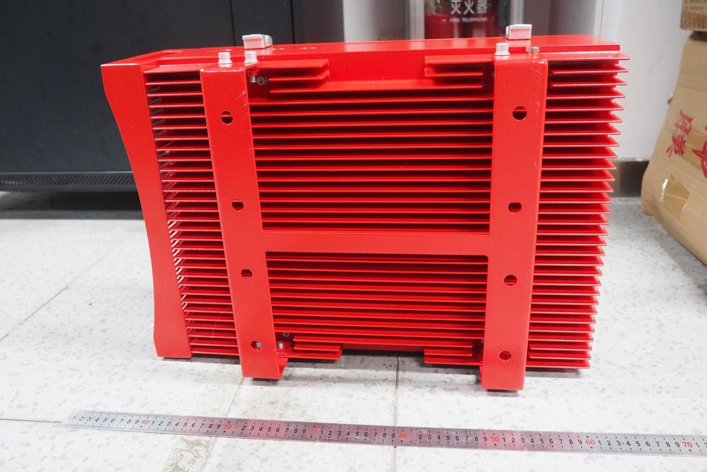
PX8RXB37
Jul 20, 2020700MHz/800MHz Public Safety Bi-directional Amplifier
Equipment Class
B9B - Part 90 Class B Industrial Booster (non-SMR)