PX8TC-2000AWS Base Station Power Amplifier
Comba Telecom Network Systems Limited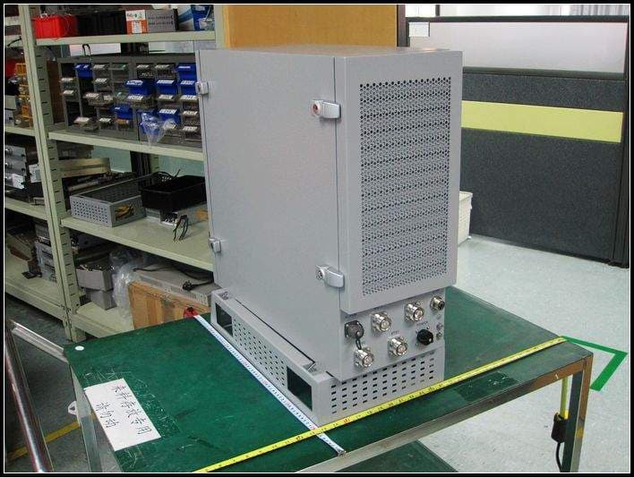
Click to zoom
Application Details
- Equipment Class
- AMP - Amplifier
- Date of Grant
- Feb 02, 2012
- Application Purpose
- Original Equipment
- Date of Application
- Feb 01, 2012
- Equipment Note
- AWS Base Station Power Amplifier
- Frequency Range
- 2110.00000000 - 2155.00000000
- Country
- China
Documents & Files
Document Text
Text extracted from the exhibit documents filed with the FCC. Open a document above to read the original.
Users Manual
USER MANUAL FOR TC-2000 TC-2000 QI Copyright - refer to title page Page 1 ENU Status : 1-1-1 TC-2000 AWS BAND SELECTIVE BASE STATION POWER AMPLIFIER USER MANUAL The information contained herein is the responsibility of and is approved by the following, to whom all enquiries should be directed in the first instance: Comba Telecom Ltd This is an unpublished work the copyright in which vests in Comba International ("Comba"). All rights reserved. The information contained herein is confidential and the property of Comba and is supplied without liability for errors or omissions. No part may be reproduced, disclosed or used except as authorised by contract or other written permission. The copyright and the foregoing restriction on reproduction and use extend to all media in which the information may be embodied. USER MANUAL FOR TC-2000 TC-2000 QI Copyright - refer to title page Page 2 ENU Status : 1-1-1 0.2 CONTENTS Section Page 0.2 CONTENTS ........................................................................................................................... 2 0.3 INDEX TO FIGURES ............................................................................................................. 4 0.4 ISSUE CONTROL .................................................................................................................. 5 0.5 SAFETY NOTICES AND ADMONISHMENTS ...................................................................... 6 1 GENERAL INFORMATION.................................................................................................... 7 2 EQUIPMENT DESCRIPTION ................................................................................................ 8 2.1 BLOCK DIAGRAM ................................................................................................................. 8 2.2 EQUIPMENT INTERNAL LAYOUT ....................................................................................... 9 2.3 KITS OF PART..................................................................................................................... 10 3 INSTALLATION ................................................................................................................... 11 3.1 INSTALLLATION CHECKLIST AND PREPARATION ........................................................ 11 3.1.1 INSTALLATION CHECKLIST .............................................................................................. 11 3.1.2 PREPARATIONS ................................................................................................................. 11 3.2 INSTALLATION PROCEDURE ........................................................................................... 12 3.2.1 SHELTER INSTALLATION .................................................................................................. 12 3.2.2 EQUIPMENT GROUNDING INSTALLATION ..................................................................... 13 3.2.3 GROUNDING CONNECTION ............................................................................................. 14 3.2.4 POWER CONNECTION ...................................................................................................... 14 3.2.5 OMT CONNECTION ............................................................................................................ 14 3.2.6 DRIP-LOOP ......................................................................................................................... 15 4 OMT ..................................................................................................................................... 16 4.1 LOCAL AND REMOTE CONNECTIONS TO OMT ............................................................. 16 4.2 OMT LOGIN ......................................................................................................................... 16 4.3 OMT CONTROL PANEL ...................................................................................................... 17 4.3.1 LOCAL CONNECTION TO OMT ......................................................................................... 17 4.3.2 REMOTE CONNECTION TO OMT .................................................................................... 18 4.3.3 CONNECTION FROM PC TO EQUIPMENT ...................................................................... 18 4.4 OMT CONFIGURATION ...................................................................................................... 20 4.5 RF PARAMETER ................................................................................................................. 21 4.5.1 SWITCH ............................................................................................................................... 21 4.5.2 ATT ...................................................................................................................................... 21 4.5.3 ALARM THRESHOLD ......................................................................................................... 22 4.5.4 POWER ................................................................................................................................ 22 4.5.5 GAIN .................................................................................................................................... 23 4.5.6 TEMPERATURE .................................................................................................................. 24 4.5.7 FREQUENCY ...................................................................................................................... 24 4.5.8 TRIGGER CONTROL .......................................................................................................... 25 4.6 ALARM INFO ....................................................................................................................... 25 4.6.1 MASTER ALARM .............................................................................................................…
Text truncated - open the document above for the full version.
Cover Letter(s)
Comba Telecom Limited 611 East Wing, No.8 Science Park West Avenue, Hong Kong Science Park, Tai Po, Hong Kong Tel: +852 2636 6861 Fax: +852 2116 6055 www.comba-telecom.com (The below is a sample for Agreement) Agreement This agreement is made between the equipment seller Comba Telecom Limited (so called seller hereafter) and (so called buyer hereafter). By signing this agreement, the buyer agrees that the device will be installed so that it is inaccessible to the public and will only be serviced by the licensee or a designated technician. Comba Telecom Limited Signature: Name: Title: Date: Buyer: Signature: Name: Title: Date:
External Photos
External Photos
ID Label/Location Info
TC2000 LABEL
RF Exposure Info
SGS-CSTC Standards Technical Services Co., Ltd. This document is issued by the Company subject to its General Conditions of Service printed overleaf, available on request or accessible at www.sgs.com/terms_and_conditions.htm and, for electronic format documents, subject to Terms and Conditions for Electronic Documents at www.sgs.com/terms_e-document.htm. Attention is drawn to the limitation of liability, indemnification and jurisdiction issues defined therein. Any holder of this document is advised that information contained hereon reflects the Company’s findings at the time of its intervention only and within the limits of Client’s instructions, if any. The Company’s sole responsibility is to its Client and this document does not exonerate parties to a transaction from exercising all their rights and obligations under the transaction documents. This document cannot be reproduced except in full, without prior written approval of the Company. Any unauthorized alteration, forgery or falsification of the content or appearance of this document is unlawful and offenders may be prosecuted to the fullest extent of the law. Unless otherwise stated the results shown in this test report refer only to the sample(s) tested and such sample(s) are retained for 90 days only. FCC ID: PX8TC-2000 RF Exposure Compliance Requirement 1. Standard requirement Systems operating under the provisions of this section shall be operated in a manner that ensures that the public is not exposed to radia frequency energy level in excess limit for maximum permissible exposure. In accordance with 47 CFR FCC Part 2 Subpart J, section 2.1091 this device has been defined as a mobile device whereby a distance of 0.2m normally can be maintained between the user and the device. (a) Limits for Occupational / Controlled Exposure Frequency Range (MHz) Electric Field Strength (E) (V/m) Magnetic Field Strength (H) (A/m) Power Density (S)(mW/cm 2 ) Averaging Times ׀E׀ 2 , ׀H׀ 2 or S (minutes) 0.3-3.0 614 1.63 (100)* 6 3.0-30 1842/f 4.89/f (900/f)* 6 30-300 61.4 0.163 1.0 6 300-1500 F/300 6 1500-100000 5 6 (b) Limits for General Population / Uncontrolled Exposure Frequency Range (MHz) Electric Field Strength (E) (V/m) Magnetic Field Strength (H) (A/m) Power Density (S)(mW/cm 2 ) Averaging Times ׀E׀ 2 , ׀H׀ 2 or S (minutes) 0.3-1.34 614 1.63 (100)* 30 1.34-30 824/f 2.19/f (180/f)* 30 30-300 27.5 0.073 0.2 30 300-1500 F/500 30 1500-100000 1.0 30 Note: f=frequency in MHz; *Plane-wave equivalent power density SGS-CSTC Standards Technical Services Co., Ltd. This document is issued by the Company subject to its General Conditions of Service printed overleaf, available on request or accessible at www.sgs.com/terms_and_conditions.htm and, for electronic format documents, subject to Terms and Conditions for Electronic Documents at www.sgs.com/terms_e-document.htm. Attention is drawn to the limitation of liability, indemnification and jurisdiction issues defined therein. Any holder of this document is advised that information contained hereon reflects the Company’s findings at the time of its intervention only and within the limits of Client’s instructions, if any. The Company’s sole responsibility is to its Client and this document does not exonerate parties to a transaction from exercising all their rights and obligations under the transaction documents. This document cannot be reproduced except in full, without prior written approval of the Company. Any unauthorized alteration, forgery or falsification of the content or appearance of this document is unlawful and offenders may be prosecuted to the fullest extent of the law. Unless otherwise stated the results shown in this test report refer only to the sample(s) tested and such sample(s) are retained for 90 days only. 2. MPE Calculation Method S (mW/cm 2 )=P*G/4Pi*R 2 S= Power Density (mW/cm 2 ) P=Peak RF conducted output Power (mW) G=EUT Antenna numeric gain (numeric) R= Separation distance between radiator and human body (cm); R= SPiGP*4/)*( From the maximum EUT RF output power, as well as the gain of the used antenna, according to the RF power density limit above, the minimum distance between the antenna and human body will be calculated. 3. Calculated Result For downlink: CDMA: Frequency (MHz) F Maximum Antenna Gain (dBi) Maximum Antenna Gain (Numeric) Peak Output Power (dBm) Peak Output Power (mW) Limit of Power Density (S) (mW/cm 2 ) Minimum Distance to human body (cm) Lowest 21 125 50.63 115611.22422 5.0 479.7060 Middle 21 125 50.47 111429.45336 5.0 470.9504 Highest 21 125 50.66 116412.60294 5.0 481.3657 WCDMA: Frequency (MHz) F Maximum Antenna Gain (dBi) Maximum Antenna Gain (Numeric) Peak Output Power (dBm) Peak Output Power (mW) Limit of Power Density (S) (mW/cm 2 ) Minimum Distance to human body (cm) Lowest 21 125 50.62 115345.32578 5.0 479.1541 Middle 21 125 50.53 112979.59147 5.0 474.2149 Highest 21 125 50.65 116144.86138 5.0 480.8119 SGS-CSTC Standards Technical Services Co., Ltd. This document is issued by the Company subject to its General Conditions of Service printed overleaf, available on request or accessible at www.sgs.com/terms_and_conditions.htm and, for electronic format documents, subject to Terms and Conditions for Electronic Documents at www.sgs.com/terms_e-document.htm. Attention is drawn to the limitation of liability, indemnification and jurisdiction issues defined therein. Any holder of this document is advised that information contained hereon reflects the Company’s findings at the time of its intervention only and within the limits of Client’s instructions, if any. The Company’s sole responsibility is to its Client and this document does not exonerate parties to a transaction from exercising all their rights and obligations under the transaction documents. This document cannot be reproduced except in full, without prior written approval of the Company. Any unauthorized alteration, forgery or falsification of the content or appearance of this document is unlaw…
Text truncated - open the document above for the full version.
Test Report
SGS-CSTC Standards Technical Services Co., Ltd. 198 Kezhu Road, Scientech Park, Guangzhou Economic & Technology Development District, Guangzhou, China 510663 Tel: +86 20 82155555 Fax: +86 20 82075059 Email: [email protected] FEDERAL COMMUNICATIONS COMMISSION Registration number: 282399 Report No.: GZEM110500131201 Page: 1 of 92 FCC ID: PX8TC-2000 . Strong Yao Manager The manufacturer should ensure that all products in series production are in conformity with the product sample detailed in this report. If the product in this report is used in any configuration other than that detailed in the report, the manufacturer must ensure the new system complies with all relevant standards. The report must not be used by the client to claim product certification, approval, or endorsement by NVLAP, NIST, or any agency of the federal government. All test results in this report can be traceable to National or International Standards. This document is issued by the Company subject to its General Conditions of Service printed overleaf, available on request or accessible at www.sgs.com/terms_and_conditions.htm and, for electronic format documents, subject to Terms and Conditions for Electronic Documents at www.sgs.com/terms_e-document.htm. Attention is drawn to the limitation of liability, indemnification and jurisdiction issues defined therein. Any holder of this document is advised that information contained hereon reflects the Company’s findings at the time of its intervention only and within the limits of Client’s instructions, if any. The Company’s sole responsibility is to its Client and this document does not exonerate parties to a transaction from exercising all their rights and obligations under the transaction documents. This document cannot be reproduced except in full, without prior written approval of the Company. Any unauthorized alteration, forgery or falsification of the content or appearance of this document is unlawful and offenders may be prosecuted to the fullest extent of the law. Unless otherwise stated the results shown in this test report refer only to the sample(s) tested and such sample(s) are retained for 90 days only 1 Cover Page TEST REPORT Application No.: GZEM1105001312RF Applicant: Comba Telecom Ltd. FCC ID: PX8TC-2000 Equipment Under Test (EUT): Product Name: AWS Base Station Power Amplifier Model No.: TC-2000 Trade Mark: Comba Frequency Band: Downlink: 2110MHz to 2155MHz Uplink: 1710MHz to 1755MHz Standards: FCC Part 27, FCC Part 2 Date of Receipt: 2011-04-24 Date of Test: 2011-04-25 to 2011-05-30 Date of Issue: 2011-11-08 Test Result : Pass* * In the configuration tested, the EUT detailed in this report complied with the standards specified above. SGS-CSTC Standards Technical Services Co., Ltd. Report No.: GZEM110500131201 Page: 2 of 92 FCC ID: PX8TC-2000 This document is issued by the Company subject to its General Conditions of Service printed overleaf, available on request or accessible at www.sgs.com/terms_and_conditions.htm and, for electronic format documents, subject to Terms and Conditions for Electronic Documents at www.sgs.com/terms_e-document.htm. Attention is drawn to the limitation of liability, indemnification and jurisdiction issues defined therein. Any holder of this document is advised that information contained hereon reflects the Company’s findings at the time of its intervention only and within the limits of Client’s instructions, if any. The Company’s sole responsibility is to its Client and this document does not exonerate parties to a transaction from exercising all their rights and obligations under the transaction documents. This document cannot be reproduced except in full, without prior written approval of the Company. Any unauthorized alteration, forgery or falsification of the content or appearance of this document is unlawful and offenders may be prosecuted to the fullest extent of the law. Unless otherwise stated the results shown in this test report refer only to the sample(s) tested and such sample(s) are retained for 90 days only. Please refer to section 3 of this report for further details. SGS-CSTC Standards Technical Services Co., Ltd. Report No.: GZEM110500131201 Page: 3 of 92 FCC ID: PX8TC-2000 This document is issued by the Company subject to its General Conditions of Service printed overleaf, available on request or accessible at www.sgs.com/terms_and_conditions.htm and, for electronic format documents, subject to Terms and Conditions for Electronic Documents at www.sgs.com/terms_e-document.htm. Attention is drawn to the limitation of liability, indemnification and jurisdiction issues defined therein. Any holder of this document is advised that information contained hereon reflects the Company’s findings at the time of its intervention only and within the limits of Client’s instructions, if any. The Company’s sole responsibility is to its Client and this document does not exonerate parties to a transaction from exercising all their rights and obligations under the transaction documents. This document cannot be reproduced except in full, without prior written approval of the Company. Any unauthorized alteration, forgery or falsification of the content or appearance of this document is unlawful and offenders may be prosecuted to the fullest extent of the law. Unless otherwise stated the results shown in this test report refer only to the sample(s) tested and such sample(s) are retained for 90 days only. 2 Version Revision Record Version Chapter Date Modifier Remark 00 2011-11-08 Original Authorized for issue by: Tested By 2011-05-13 to 2011-05-30 (Daniel Hew) /Project Engineer Date Prepared By 2011-09-15 (Daniel Hew) /Clerk Date Checked By 2011-11-08 (Jeffrey Chen) /Reviewer Date SGS-CSTC Standards Technical Services Co., Ltd. Report No.: GZEM110500131201 Page: 4 of 92 FCC ID: PX8TC-2000 This document is issued by the Company subject to its General Conditions of Service printed overleaf, available on request or accessi…
Text truncated - open the document above for the full version.
Test Report
SGS-CSTC Standards Technical Services Co., Ltd. Report No.: GZEM110500131201 Page: 47 of 91 FCC ID: PX8TC-2000 This document is issued by the Company subject to its General Conditions of Service printed overleaf, available on request or accessible at www.sgs.com/terms_and_conditions.htm and, for electronic format documents, subject to Terms and Conditions for Electronic Documents at www.sgs.com/terms_e-document.htm . Attention is drawn to the limitation of liability, indemnification and jurisdiction issues defined therein. Any holder of this document is advised that information contained hereon reflects the Company’s findings at the time of its intervention only and within the limits of Client’s instructions, if any. The Company’s sole responsibility is to its Client and this document does not exonerate parties to a transaction from exercising all their rights and obligations under the transaction documents. This document cannot be reproduced except in full, without prior written approval of the Company. Any unauthorized alteration, forgery or falsification of the content or appearance of this document is unlawful and offenders may be prosecuted to the fullest extent of the law. Unless otherwise stated the results shown in this test report refer only to the sample(s) tested and such sample(s) are retained for 90 days only. 7.2.3 Band Edge& Intermodulation Test Date: 2011-04-25 Test Requirement: FCC part 27.53(h) (1) Compliance with this provision is based on the use of measurement instrumentation employing a resolution bandwidth of 1 megahertz or greater. However, in the 1 megahertz bands immediately outside and adjacent to the licensee's frequency block, a resolution bandwidth of at least one percent of the emission bandwidth of the fundamental emission of the transmitter may be employed. The emission bandwidth is defined as the width of the signal between two points, one below the carrier center frequency and one above the carrier center frequency, outside of which all emissions are attenuated at least 26 dB below the transmitter power. Test Method: FCC part 2.1051&2-11-04/EAB/RF EUT Operation: Status: Drive the EUT to maximum output power. Conditions: Normal conditions Application: Cellular Band RF output ports Test Configuration: Fig.3. Band edge and Intermodulation test configuration SGS-CSTC Standards Technical Services Co., Ltd. Report No.: GZEM110500131201 Page: 48 of 91 FCC ID: PX8TC-2000 This document is issued by the Company subject to its General Conditions of Service printed overleaf, available on request or accessible at www.sgs.com/terms_and_conditions.htm and, for electronic format documents, subject to Terms and Conditions for Electronic Documents at www.sgs.com/terms_e-document.htm . Attention is drawn to the limitation of liability, indemnification and jurisdiction issues defined therein. Any holder of this document is advised that information contained hereon reflects the Company’s findings at the time of its intervention only and within the limits of Client’s instructions, if any. The Company’s sole responsibility is to its Client and this document does not exonerate parties to a transaction from exercising all their rights and obligations under the transaction documents. This document cannot be reproduced except in full, without prior written approval of the Company. Any unauthorized alteration, forgery or falsification of the content or appearance of this document is unlawful and offenders may be prosecuted to the fullest extent of the law. Unless otherwise stated the results shown in this test report refer only to the sample(s) tested and such sample(s) are retained for 90 days only. Test Procedure: Conducted Emissions test procedure: a) Connect the equipment as illustrated, with the notch filter by-passed, when the output power is over the max value of the Spectrum Analyzer, add the attenuator to avoid destroying the facility. b) Set the center frequency of the spectrum analyzer to the assigned transmitter frequency, key the transmitter, and set the level of the carrier to the full scale reference line. c) do not apply any tone to modulate the EUT. d) Adjust the spectrum analyzer for the following settings: 1) Resolution Bandwidth,( base the standard, apply the different set),here is 100KHz for frequency band less than 1GHz, 1MHz for frequency over 1GHz; 2) Video Bandwidth refer to standard requirement. e) Adjust the center frequency of the spectrum analyzer for incremental coverage of the range from: 1) the lowest radio frequency generated in the equipment, it can be 9KHz base the test method, here select 30MHz as lowest frequency start point; 2) the highest radion frequency shall higher than 10 times of carrier frequency; f ) Record the frequencies and levels of spurious emissions from step e) Remark: The notch filter is used for avoid the EUT fundamental carrier output power making the spectrum overload and the harmonic spurious brought by it. When the EUT fundamental carrier is not enough to make the status, the notch filter could be not used. SGS-CSTC Standards Technical Services Co., Ltd. Report No.: GZEM110500131201 Page: 49 of 91 FCC ID: PX8TC-2000 This document is issued by the Company subject to its General Conditions of Service printed overleaf, available on request or accessible at www.sgs.com/terms_and_conditions.htm and, for electronic format documents, subject to Terms and Conditions for Electronic Documents at www.sgs.com/terms_e-document.htm . Attention is drawn to the limitation of liability, indemnification and jurisdiction issues defined therein. Any holder of this document is advised that information contained hereon reflects the Company’s findings at the time of its intervention only and within the limits of Client’s instructions, if any. The Company’s sole responsibility is to its Client and this document does not exonerate parties to a transaction from exercising all their rights and obligations under the transaction documents. This docume…
Text truncated - open the document above for the full version.
Test Setup Photos
Test Setup Photos 30MHz ~ 1GHz Radiated Emission Above 1GHz Radiated Emission
Contact Information
Applicant
Ronin Gong(Director)
Technical Contact
SGS-CSTC Standards Technical Services Co., Ltd.Daniel He
[email protected]+86 20 82155314
198 KEZHU Road, Scientech Park · Guangzhou · China
Non-Technical Contact
SGS-CSTC Standards Technical Services Co., Ltd.Millie Li
[email protected]+86 20 82155332
Test Firm
SGS-CSTC Standards Technical Services Co., LtdJerry Chan
Technical Specifications
| # | Rule Parts | Frequency Range | Power Output | Emission | Tolerance |
|---|---|---|---|---|---|
| 1 | 27 | 2.11 GHz - 2.15 GHz | 116.4 W | F9W | Amp |
Other Applications from Comba Telecom Network Systems Limited

PX8-SW-J
Jan 01, 2025SailaJoint
Equipment Class
DTS - Digital Transmission System
PX8RX14V3-A
Dec 08, 2024Public Safety UHF and VHF Dualband Bi-Directional Amplifier
Equipment Class
B9A - Part 90 Class A Industrial Booster (non-SMR)
PX8CFNG-MU
May 18, 2023Comflex NG
Equipment Class
B2I - Part 20 Industrial Booster (CMRS)
PX8MIRCU-S24
May 27, 2021Multi internal Remote Control Unit
Equipment Class
JAB - Part 15 Class B Digital Device
PX8RXB37
Jul 20, 2020700MHz/800MHz Public Safety Bi-directional Amplifier
Equipment Class
B9B - Part 90 Class B Industrial Booster (non-SMR)