PY4-WA110Wireless LAN Access Point
Remotek Corporation
Click to zoom
Application Details
- Equipment Class
- DTS - Digital Transmission System
- Date of Grant
- Jan 15, 2003
- Application Purpose
- Original Equipment
- Date of Application
- Jan 15, 2003
- Equipment Note
- Wireless LAN Access Point
- Frequency Range
- 2412.00000000 - 2462.00000000
- Company
- Remotek Corporation
- Country
- Taiwan
Documents & Files
Document Text
Text extracted from the exhibit documents filed with the FCC. Open a document above to read the original.
Users Manual
Wireless LAN Access Point(RFMD) WA110 User Manual 1 Wireless LAN Access Point(RFMD) WA110 User Manual Version 1.0 Dec 2002 Wireless LAN Access Point(RFMD) WA110 User Manual 2 Copyright Statement No part of this publication may be reproduced in any form or by any means, or used to make any derivative such as translation, transformation, or adaptation as stipulated by the United States Copyright ACT of 1976. This device complies with Part 15 of the FCC rules. Operation is subject to the following two conditions: (1) This device may not cause harmful interference, and (2) This device must accept any interference received including interference that may cause undesired operation. FCC Certifications This equipment has been tested and found to comply with the limits for a Class B digital device, pursuant to Part 15 of the FCC Rules. These Limits are designed to provide reasonable protection against harmful interference in a residential installation. This equipment generates uses and can radiate radio frequency energy and, if not installed and used in accordance with the instructions, may cause harmful interference to radio communications. However, there is no guarantee that interference will not occur in a particular installation. If this equipment does cause harmful interference to radio or television reception, which can be determined by turning the equipment off and on, the user is encouraged to try to correct the interference by one or more of the following measures: z Reorient or relocate the receiving antenna z Increase the separation between the equipment and receiver z Connect the equipment into an outlet on a circuit different from that to which the receiver is connected z Consult the dealer or an experienced radio/TV technician for help FCC Caution: To assure continued compliance,(example – use only shielded interface cables when connecting to computer or peripheral devices).Any changes or modifications not expressly approved by the part responsible for compliance could void your authority to operate the equipment. Wireless LAN Access Point(RFMD) WA110 User Manual 3 FCC RF Radiation Exposure Statement This equipment complies with FCC RF radiation exposure limits set forth for an uncontrolled environment. This equipment should be installed and operated with a minimum distance of 20 centimeters between the radiator and your body. Wireless LAN Access Point(RFMD) WA110 User Manual 4 Contents 1. Introduction: ...................................................................................................... 5 2. Features: ............................................................................................................. 5 3. Environment Requirement: ................................................................................ 6 4. Install AP SNMP Manager:.................................................................................. 7 4.1. InstallShield Wizard .................................................................................7 4.2. Choose Destination Location ....................................................................7 4.3. Select Program Folder..............................................................................8 4.4. Start Copying Files ..................................................................................8 4.5. InstallShield Wizard Complete ..................................................................9 4.6. Connect Access Point (AP) to Computer .................................................. 10 4.7. Setting Up IP address of Windows 2000.................................................. 10 5. Modify Configurations by AP SNMP Manager: .................................................12 5.1. AP SNMP Manager................................................................................. 12 5.2. Close Connection of AP .......................................................................... 13 5.3. Download Changes to AP or Refresh Setting from AP ............................... 13 5.4. Modify Bridge........................................................................................ 14 5.5. Modify Wireless LAN .............................................................................. 15 5.6. Get Statistics......................................................................................... 18 5.7. Enable SNMP Traps................................................................................ 20 5.8. Modify Authority Configuration ............................................................... 21 5.9. Reset AP or Restore Defaults.................................................................. 21 6. Wireless Lan AP Operation Modes: ..................................................................22 6.1. Wireless LAN Access Point Mode ............................................................. 22 6.2. AP Client Mode...................................................................................... 23 6.3. AP Bridge Mode .................................................................................... 23 7. Specifications: ..................................................................................................25 Wireless LAN Access Point(RFMD) WA110 User Manual 5 1. Introduction: Access Point (AP) provides capabilities of connecting Wireless LAN to Ethernet. Adaptors can connect to Ethernet through AP. 2. Features: Comply with 11 Mbps IEEE802.11b high data rate specification Seamless roaming within the 802.11 and 802.11b wireless LAN infrastructure Support 10Base-T networks Optimized wired-to-wireless data transfer Independent network operating system Enables roaming capability Antenna diversity for maximum communication, reliability and operating range Support SNMP and web-based management Watchdog timer Easy to install and user friendly Bridge function including point-to-point, and point-to-multipoint. Wireless Repeater Mode increase the coverage area of an ESS.…
Text truncated - open the document above for the full version.
RF Exposure Info
Training Research Co., Ltd. 255 Nanyang Street, Shijr, Taipei Hsien 221, Taiwan, R.O.C. TEL: 886-2-26935155 FAX: 886-2-26934440 TRCSince1985 ® Measurement of MPE 1. Foreword In adopt with the Human Exposure IEEE C95.1, and according to the FCC 1.1310. The Maximum Permissible Exposure (MPE) is obligated to measure in order to prove the safety of radiation harmfulness to the human body. The Gain of the antenna used is measured in an Anechoic chamber. The maximum total power to the antenna is to be recorded. By adopting the Friis Transmission Formula and the power gain of the antenna, we can find the distance right away from the product, where the limit of the MPE is. 2. Description of EUT EUT : Wireless LAN Access Point Model No. : WA-110 Classification : Mobile Device (i) Under normal use condition, the antenna is at least 20cm away from the user; (ii) Warning statement for keeping 20cm separation distance and the prohibition of operating next to the person has been printed in the user’s manual FCC ID : PY4-WA110 Frequency Range : 2412 MHz-2462 MHz Antenna type : 1 PCB antenna Modulation Skill : DBPSK / DQPSK / CCK Power Type : Powered by the Power adapter M/N: SA0105-A I/P: 100-240VAC, 50-60Hz O/P: +5VDC, 1.4A Applicant : Remotek Corporation 6F-6, No.77, Sect.1, Hsin Tai Wu Rd., His-chih, Taipei, Taiwan, R.O.C. Training Research Co., Ltd. 255 Nanyang Street, Shijr, Taipei Hsien 221, Taiwan, R.O.C. TEL: 886-2-26935155 FAX: 886-2-26934440 TRCSince1985 ® 3. Limits for Maximum Permissible Exposure (MPE) Frequency Range (MHz) Electric Field Strength (V/m) Magnetic Filed Strength (H) (A/m) Power Density (S) (mW/cm2) Averaging Time |E| 2 , |H| 2 or S (minutes) (A) Limits for Occupational/Controlled Exposure 0.3-3.0 614 1.63 100 6 3.0-30 1842/f 4.89/f 900/f 2 6 30-300 61.4 0.163 1.0 6 300-1500 -- -- f/300 6 1500-100,000 -- -- 5 6 (B) Limits for General Population/Uncontrolled Exposure 0.3-1.34 614 1.63 100 30 1.34-30 824/f 2.19/f 180/f 2 30 30-300 27.5 0.073 0.2 30 300-1500 -- -- f/1500 30 1500-100,000 -- -- 1.0 30 [The EUT is tested in transmit and receive modes and in the first, middle and the last channel separately. The following shows only our observation have the greatest emissions.] According to OET BULLETIN 56 Fourth Edition/August 1999, equation for predicting RF fields, by the Friis Transmission Formula: Power density at the specific separation (Mobile): 22 22 /10076.1 )20(4 135.164.47 4 cmmW R PG S − ×= × == ππ Estimated safe separation: cm PG R074.2 4 135.164.47 4 = × == ππ Remarks: "The safe estimated separation that the user must maintain from the antenna is at least 2.074 cm." Where: S = power density (in appropriate units, e.g. mW/cm2) P = power input to the antenna (in appropriate units, e.g., mW) G = power gain of the antenna in the direction of interest relative to an isotropic radiator R = distance to the center of radiation of the antenna (appropriate units, e.g., cm) The Numeric gain G of antenna with a gain specified in dB is determined by: G = Log -1 (dB antenna gain/10) G = Log -1 (0.55 / 10) = 1.135 0 90 180 270 0 90 180 270 0 90 180 270 0 90 180 270 0 90 180 270 AP 7 MET AL ANT . FRONT ( )
Test Report
Test Report ----------------------------------------------------------------------------- 3/40 Report No.: R2415006, FCC Part 15 Training Research Co., Ltd., TEL: 886-2-26935155, Fax: 886-2-26934440 Tables of Contents I. GENERAL ........................................................................................................................ 5 1.1 Introduction ................................................................................................................. 5 1.2 Description of EUT ..................................................................................................... 5 1.3 Test method ................................................................................................................. 5 1.4 Description of Support Equipment ............................................................................. 6 1.5 Configuration of System Under Test .......................................................................... 8 1.6 Verify the Frequency and Channel ............................................................................. 11 1.7 Test Procedure ........................................................................................................... 12 1.8 Location of the Test Site ............................................................................................ 12 1.9 General Test Condition .............................................................................................. 12 II. Section 15.203 : Antenna Requirement........................................................................... 13 III. Section 15.207 : Power Line Conducted Emissions for AC Powered Units ............... 14 3.1 Test Condition & Setup ............................................................................................. 14 3.2 List of Test Instruments ............................................................................................. 14 3.3 Test Result of Conducted Emissions ......................................................................... 15 Table 1 Conducted emissions of channel 01 ........................................................... 15 Table 2 Conducted emissions of Channel 06 .......................................................... 16 Table 3 Conducted emissions of Channel 11 .......................................................... 17 IV. Section 15.247(a) : Technical Description of the EUT................................................... 18 V. Section 15.247(a)(2) : Bandwidth for Direct Sequence System ................................... 19 5.1 Test Condition & Setup ............................................................................................. 19 5.2 Test Instruments Configuration ................................................................................. 19 5.3 List of Test Instruments ............................................................................................. 19 5.4 Test Result of Bandwidth ........................................................................................... 20 Channel 01 ................................................................................................................. 21 Channel 06 ................................................................................................................. 22 Channel 11 ................................................................................................................. 23 Test Report ----------------------------------------------------------------------------- 4/40 Report No.: R2415006, FCC Part 15 Training Research Co., Ltd., TEL: 886-2-26935155, Fax: 886-2-26934440 VI. Section 15.247(b) : Power Output .................................................................................. 24 6.1 Test Condition & Setup ............................................................................................. 24 6.2 List of Test Instruments ............................................................................................. 24 6.3 Test Result ................................................................................................................. 25 VII. Section 15.247(c) : Spurious Emissions (Radiated) ................................................... 26 7.1 Test Condition & Setup ........................................................................................... 26 7.2 List of Test Instruments ........................................................................................... 27 7.3 Test Result of Spurious Radiated Emissions ........................................................... 28 Table 4 Radiated emissions of Horizontal for 30MHz to 1GHz ........................ 28 Table 5 Radiated emissions of Vertical for 30MHz to 1GHz ............................ 29 Table 6 Above 1GHz radiated emissions of Horizontal of CH1 ........................ 30 Table 7 Above 1GHz radiated emissions of Vertical of CH1 ............................ 30 Table 8 Above 1GHz radiated emissions of Horizontal of CH6 ........................ 31 Table 9 Above 1GHz radiated emissions of Vertical of CH6 ............................ 31 Table 10 Above 1GHz radiated emissions of Horizontal of CH11 ...................... 32 Table 11 Above 1GHz radiated emissions of Vertical of CH11 .......................... 32 7.4 Test Result of Bandedge............................................................................................ 33 Channel 01 ............................................................................................................... 34 Channel 11 ............................................................................................................... 35 VIII. Section 15.247(d) : Power Spectral Density ................................................................ 36 8.1 Test Condition & Setup ........................................................................................... 36 8.2 Test Instruments Configuration ..................…
Text truncated - open the document above for the full version.
Test Setup Photos
Test Setup Photos ------------------------------------------------------------------------- 1/2 FCC ID: PY4-WA110 Training Research Co., Ltd., TEL: 886-2-26935155, Fax: 886-2-26934440 Conducted Test Setup Placement: (Photographs) Front View of the Test Configuration Side View of the Test Configuration Test Setup Photos ------------------------------------------------------------------------- 2/2 FCC ID: PY4-WA110 Training Research Co., Ltd., TEL: 886-2-26935155, Fax: 886-2-26934440 Radiated Test Setup Placement: Front View of the Test Configuration Rear View of the Test Configuration
Contact Information
Applicant
Owen Chen(manager)
Test Firm
Training Research Co., Ltd.Jack Tsai
Technical Specifications
| # | Rule Parts | Frequency Range | Power Output |
|---|---|---|---|
| 1 | 15C | 2.41 GHz - 2.46 GHz | 48.00 mW |
Other Applications from Remotek Corporation
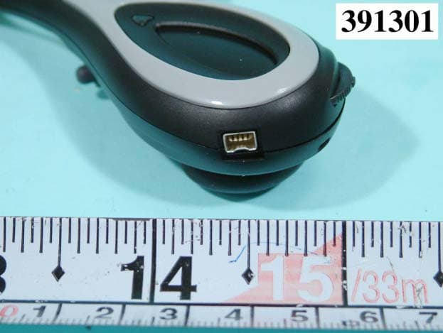
PY4-BK1010
Oct 23, 2003BLUETOOTH HEADSET
Equipment Class
DSS - Part 15 Spread Spectrum Transmitter
PY4-WP320
Jun 08, 2003Wireless LAN PC Card
Equipment Class
DTS - Digital Transmission System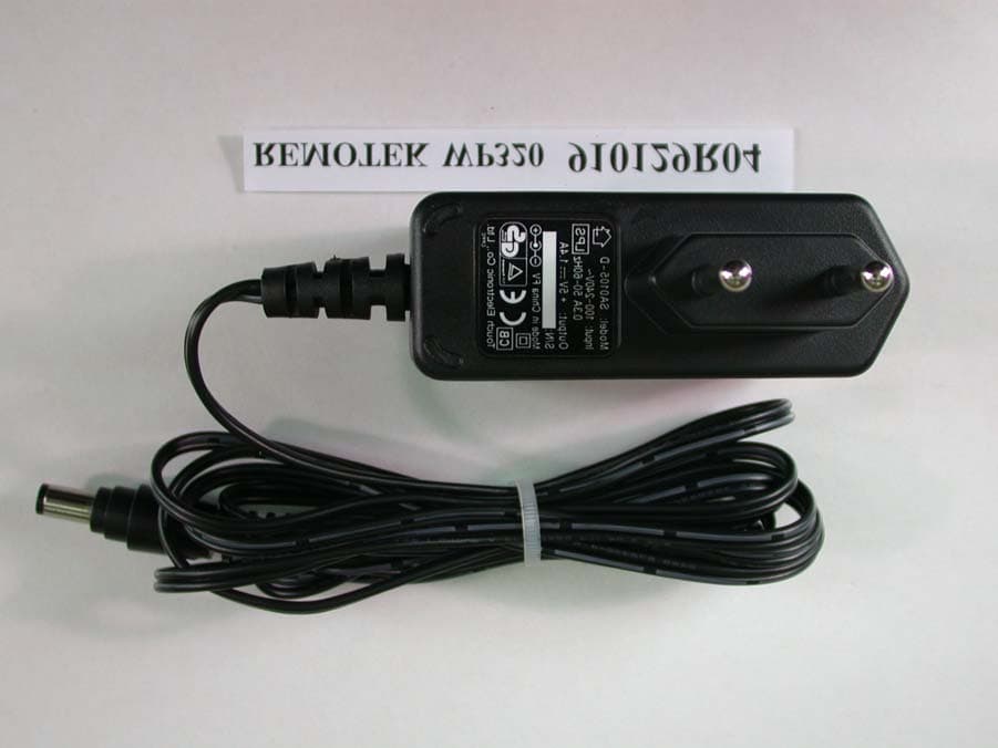
PY4-WA220
Apr 11, 2002Wireless LAN Access Point
Equipment Class
DTS - Digital Transmission System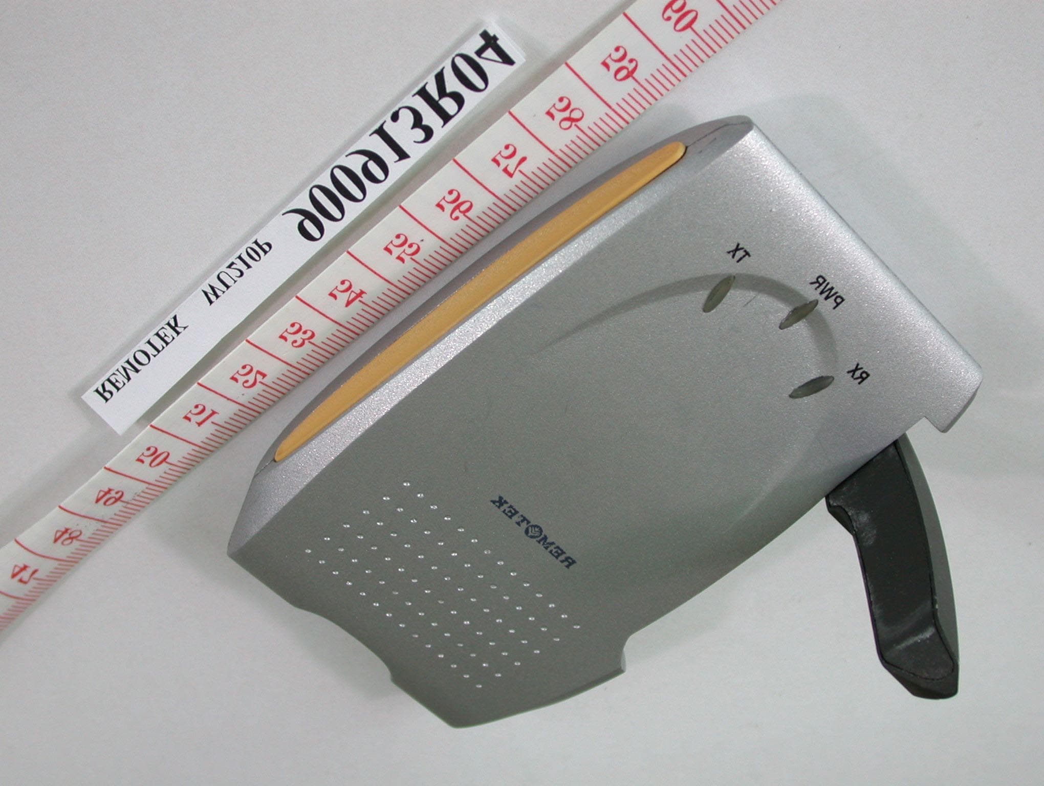
PY4WU210P
Oct 27, 2001USB Wireless LAN
Equipment Class
DTS - Digital Transmission System