PY4WU210PUSB Wireless LAN
Remotek Corporation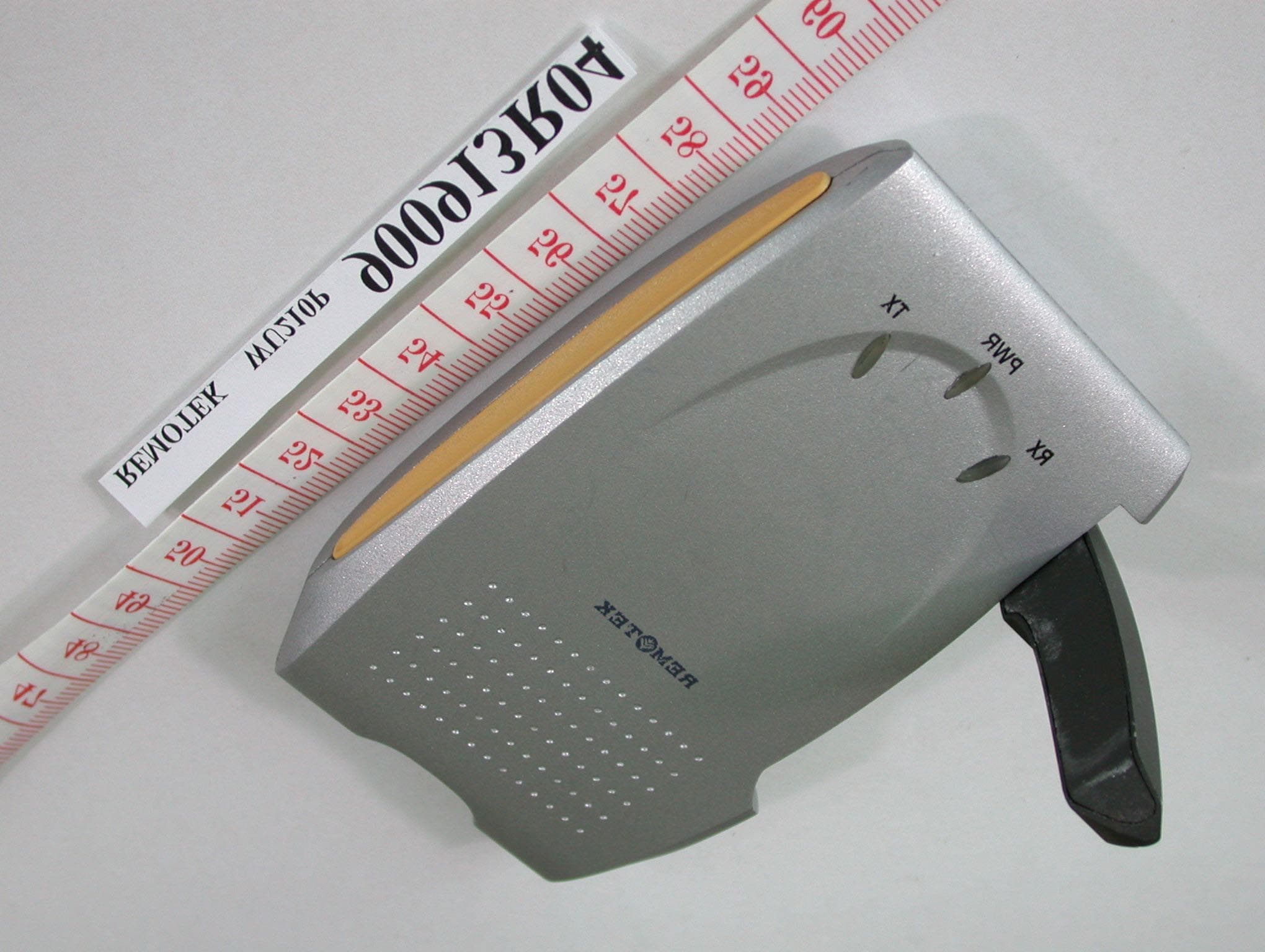
Click to zoom
Application Details
- Equipment Class
- DTS - Digital Transmission System
- Date of Grant
- Oct 27, 2001
- Application Purpose
- Original Equipment
- Date of Application
- Oct 27, 2001
- Equipment Note
- USB Wireless LAN
- Frequency Range
- 2412.00000000 - 2462.00000000
- Company
- Remotek Corporation
- Country
- Taiwan
Documents & Files
Document Text
Text extracted from the exhibit documents filed with the FCC. Open a document above to read the original.
Users Manual
User Manual WU210P USB Adaptor Version 1.0—July 2001 2 Copyright Statement No part of this publication may be reproduced in any form or by any means or used to make any derivative such as translation, transformation, or adaptation without permission form Remotek Corporation, as stipulated by the United States Copyright ACT of 1976. FCC Certifications This equipment has been tested and found to comply with the limits for a Class B digital device, pursuant to Part 15 of the FCC Rules. These Limits are designed to provide reasonable protection against harmful interference in a residential installation. This equipment generates, uses and can radiate radio frequency energy and, if not installed and used in accordance with the instructions, may cause harmful interference to radio communications. However, there is no guarantee that interference will not occur in a particular installation. If this equipment does cause harmful interference to radio or television reception, which can be determined by turning the equipment off and on, the user is encouraged to try to correct the interference by one or more of the following measures: z Reorient or relocate the receiving antenna z Increase the separation between the equipment and receiver z Connect the equipment into an outlet on a circuit different from that to which the receiver is connected z Consult the dealer or an experienced radio/TV technician for help Shielded interface cables must be used in order to comply with emission limits. You are cautioned that changes or modifications not expressly approved by the part responsible for compliance could void your authority to operate the equipment FCC RF Radiation Exposure Statement This equipment complies with FCC RF radiation exposure limits set forth for an uncontrolled environment. This equipment should be installed and operated with a minimum distance of 20 centimeters between the radiator and your body. This device complies with Part 15 of the FCC rules. Operation is subject to the following two conditions: (1) This device may not cause harmful interference, and (2) This device must accept any interference received. Including interference that may cause undesired operation. 3 Contents 1. Introduction..........................................................................................................4 2. Installation Overview..........................................................................................5 3. Installation Procedure of WU210P....................................................................6 4. Configuration Utility............................................................................................9 4.1. “Status” tab..................................................................................................9 4.2. “Statistics” tab............................................................................................ 11 4.3. “Site Survey” tab........................................................................................12 4.4. “Encryption” tab.........................................................................................13 4.5. “Advanced” tab...........................................................................................14 4.6. “Version” tab...............................................................................................14 5. Technical specifications of WU210P................................................................15 4 1. Introduction Thank you for purchasing USB Wireless LAN Adaptor-WU210P from Remotek Corp.. This quick start manual will assist you with the installation procedure. The package you have received should contain the following items: z WU210P USB WLAN Adaptor z USB to Mini USB Cable z User manual z CD ROM containing Wireless LAN Management utility and drivers Note: if anything is missing, please contact your vendor. 5 2. Installation Overview Here are some steps you will perform in establishing your wireless network connection: z Install the Access Point at first. AP is needed in case of infrastructure network mode. z Install the software using the Installation CD-ROM. z Insert the Wireless LAN adaptor (WU210P). z Install the driver of USB WLAN adaptor. z Install the network protocols required to communicate on your network. Most likely you will need the TCP/IP protocol. 6 3. Installation Procedure of WU210P Please follow the following steps one by one in order to install the USB WLAN Adaptor successfully. Step 1. Power on your computer and allow Window 95/98/2000 to load fully. Step 2. Be sure that there is no USB adaptor inserted yet. Step 3. Insert the given Installation CD-ROM and then click on the setup.exe. Step 4. Give the path of the destination folder. To change the path of the destination folder click on Browse After all, click Next to continue. 7 Step 5. Type the program folder name. Step 6. Last check before install the program. Step 7. It takes a few seconds for copying the utility files and then click on Finish to complete the installation Step 8. Message that notifies you to restart your computer may pop up. Select Yes. It will shut down your computer and restart. 8 Step 9. Insert the WU210P - USB WLAN Adaptor into USB slot, windows will install the driver automatically. Step 10. If the Configuration & Monitor Utility icon is not on system tray, it shows the installation is not successful. Select Uninstall WLAN Monitor Utility in program folder to remove. Restart your computer after uninstalling the driver to make the changes effective. Step 11. If you find the Red sign on system tray, which means your Wireless LAN Adaptor haven’t connected to an Access Point Successfully. Please double-click on the red sign on system tray to open Configuration & Monitor Utility. Select Site Survey tab, and click Re-Scan to find all site nearby. You may double-click on the site that you want to connect to. Step 12. Modify TCP/IP settings of Windows. You can select either Static or DHCP …
Text truncated - open the document above for the full version.
External Photos
Page 1 ANNEX PHOTOGRAPHS OF EUT Page 2
ID Label/Location Info
Wireless LAN USB Adaptor 802.11b Compliant 11 Mbps Data Rate 0560 made in Taiwan FCC ID: PY4 WU210P Tested To Comply withFCC Standards Wireless LAN USB Adaptor 802.11b Compliant 11 Mbps Data Rate made in Taiwan FCC ID: PY4WU210P 0560 Tested To Comply with FCC Standards
Internal Photos
Page 3 Page 4
Internal Photos
Page 5 Page 6
Operational Description
FCC ID: PY4WU210P ADT No.900913R04 Operational Description The transmitter of the EUT (USB Wireless LAN) is powered by host equipment from USB port. The antenna is printed dipole antenna, and there is no antenna connector. Under normal use condition, the user has to keep at least 20cm separation distance between radiator and the body of the user. The other instruction, please have a look at the users manual. DSSS Information This device is Direct Sequence Spread Spectrum, the data is mixed by pseudorandom code which is an orthogonal code. The mixed data is digital modulated by BPSK and QPSK technique depends on the data rates. The CCK coding is applied for increasing the data rate, and also the processing gain will be increased. The bit rates are 1,2,5.5,11Mbps, the symbol rates are 1,1,1.375,1.375Mbps, the chip rates are always 11Mbps. So, the Chip/symbol is 11,11,8 and 8 respectively. Although is higher bit rate, the processing gain is lower than 10, but the CCK coding used in higher bit rate will provide 2.2dB coding gain.
Test Report
FCC ID: PY4WU210P Report No.: RF900913R04 1 Issued: Oct. 19, 2001 FCC TEST REPORT REPORT NO.: RF900913R04 MODEL NO.: WU210P RECEIVED: Sept.13, 2001 TESTED: Sept. 14 ~ Sept. 15, 2001 APPLICANT: REMOTEK CORPORATION ADDRESS: 6F-6, No. 77, Sec. 1, Hsin Tai Wu Rd., Taipei, Taiwan, R.O.C. ISSUED BY: Advance Data Technology Corporation LAB LOCATION: 47 14th Lin, Chiapau Tsun, Linko, Taipei, Taiwan, R.O.C. This test report consists of 48 pages in total. It may be duplicated completely for legal use with the approval of the applicant. It should not be reproduced except in full, without the written approval of our laboratory. The client should not use it to claim product endorsement by CNLA, NVLAP or any government agencies. The test results in the report only apply to the tested sample. 0528 Lab Code: 200102-0 FCC ID: PY4WU210P Report No.: RF900913R04 2 Issued: Oct. 19, 2001 Table of Contents 1CERTIFICATION ...........................................................................................4 2SUMMARY OF TEST RESULTS...................................................................5 3GENERAL INFORMATION ...........................................................................6 3.1GENERAL DESCRIPTION OF EUT..............................................................6 3.2DESCRIPTION OF TEST MODES................................................................7 3.3GENERAL DESCRIPTION OF APPLIED STANDARDS ...............................7 3.4DESCRIPTION OF SUPPORT UNITS..........................................................8 4TEST TYPES AND RESULTS.......................................................................9 4.1CONDUCTED EMISSION MEASUREMENT ................................................9 4.1.1LIMITS OF CONDUCTED EMISSION MEASUREMENT.................................................... 9 4.1.2TEST INSTRUMENTS....................................................................................................... 9 4.1.3TEST PROCEDURES..................................................................................................... 10 4.1.4TEST SETUP .................................................................................................................. 10 4.1.5EUT OPERATING CONDITIONS..................................................................................... 11 4.1.6TEST RESULTS ..............................................................................................................12 4.2RADIATED EMISSION MEASUREMENT ...................................................18 4.2.1LIMITS OF RADIATED EMISSION MEASUREMENT ...................................................... 18 4.2.2TEST INSTRUMENTS..................................................................................................... 19 4.2.3TEST PROCEDURES..................................................................................................... 20 4.2.4TEST SETUP .................................................................................................................. 21 4.2.5EUT OPERATING CONDITIONS..................................................................................... 21 4.2.6TEST RESULTS ..............................................................................................................22 4.36DB BANDWIDTH MEASUREMENT ..........................................................26 4.3.1LIMITS OF 6dB BANDWIDTH MEASUREMENT.............................................................. 26 4.3.2TEST INSTRUMENTS..................................................................................................... 26 4.3.3TEST PROCEDURE........................................................................................................ 27 4.3.4TEST SETUP .................................................................................................................. 27 4.3.5EUT OPERATING CONDITIONS..................................................................................... 27 4.3.6TEST RESULTS ..............................................................................................................28 4.4MAXIMUM PEAK OUTPUT POWER ..........................................................32 4.4.1LIMITS OF MAXIMUM PEAK OUTPUT POWER MEASUREMENT ................................. 32 4.4.2INSTRUMENTS...............................................................................................................32 4.4.3TEST PROCEDURES..................................................................................................... 33 4.4.4TEST SETUP .................................................................................................................. 33 4.4.5EUT OPERATING CONDITIONS..................................................................................... 33 4.4.6TEST RESULTS ..............................................................................................................34 4.5POWER SPECTRAL DENSITY MEASUREMENT......................................35 4.5.1LIMITS OF POWER SPECTRAL DENSITY MEASUREMENT ......................................... 35 4.5.2TEST INSTRUMENTS..................................................................................................... 35 4.5.3TEST PROCEDURE........................................................................................................ 36 4.5.4TEST SETUP .................................................................................................................. 36 4.5.5EUT OPERATING CONDITION ....................................................................................... 36 4.5.6TEST RESULTS ..............................................................................................................37 4.6BAND EDGES MEASUREMENT ................................................................41 FCC ID: PY4WU210P Report No.: RF900913R04 3 Issued: Oct. 19, 2001 4.6.1LIMITS OF BAND EDGES MEASUREMENT ....................................................…
Text truncated - open the document above for the full version.
Test Setup Photos
FCC ID: PY4WU210P Report No.: RF900913R04 46 Issued: Oct. 19, 2001 5 PHOTOGRAPHS OF THE TEST CONFIGURATION CONDUCTED EMISSION TEST FCC ID: PY4WU210P Report No.: RF900913R04 47 Issued: Oct. 19, 2001 RADIATED EMISSION TEST
Contact Information
Applicant
Owen Chen(manager)
Technical Contact
Advance Data Technology CorporationAlan Lane
[email protected]+886 3 327 0910
13-1, Lane 19, WenShan 3rd St · Taoyuan · Taiwan
Test Firm
Bureau Veritas CPS (H.K.) Ltd. Taoyuan BranchRichard Chen
Technical Specifications
| # | Rule Parts | Frequency Range | Power Output |
|---|---|---|---|
| 1 | 15C | 2.41 GHz - 2.46 GHz | 72.00 mW |
Other Applications from Remotek Corporation
PY4-BK1010
Oct 23, 2003BLUETOOTH HEADSET
Equipment Class
DSS - Part 15 Spread Spectrum Transmitter
PY4-WP320
Jun 08, 2003Wireless LAN PC Card
Equipment Class
DTS - Digital Transmission System
PY4-WA110
Jan 15, 2003Wireless LAN Access Point
Equipment Class
DTS - Digital Transmission System
PY4-WA220
Apr 11, 2002Wireless LAN Access Point
Equipment Class
DTS - Digital Transmission System