PY7A3880110Mobile phone with Bluetooth, WLAN 802.11bgn, GPS/A-GPS, ANT+ and FM Rx
Sony Corporation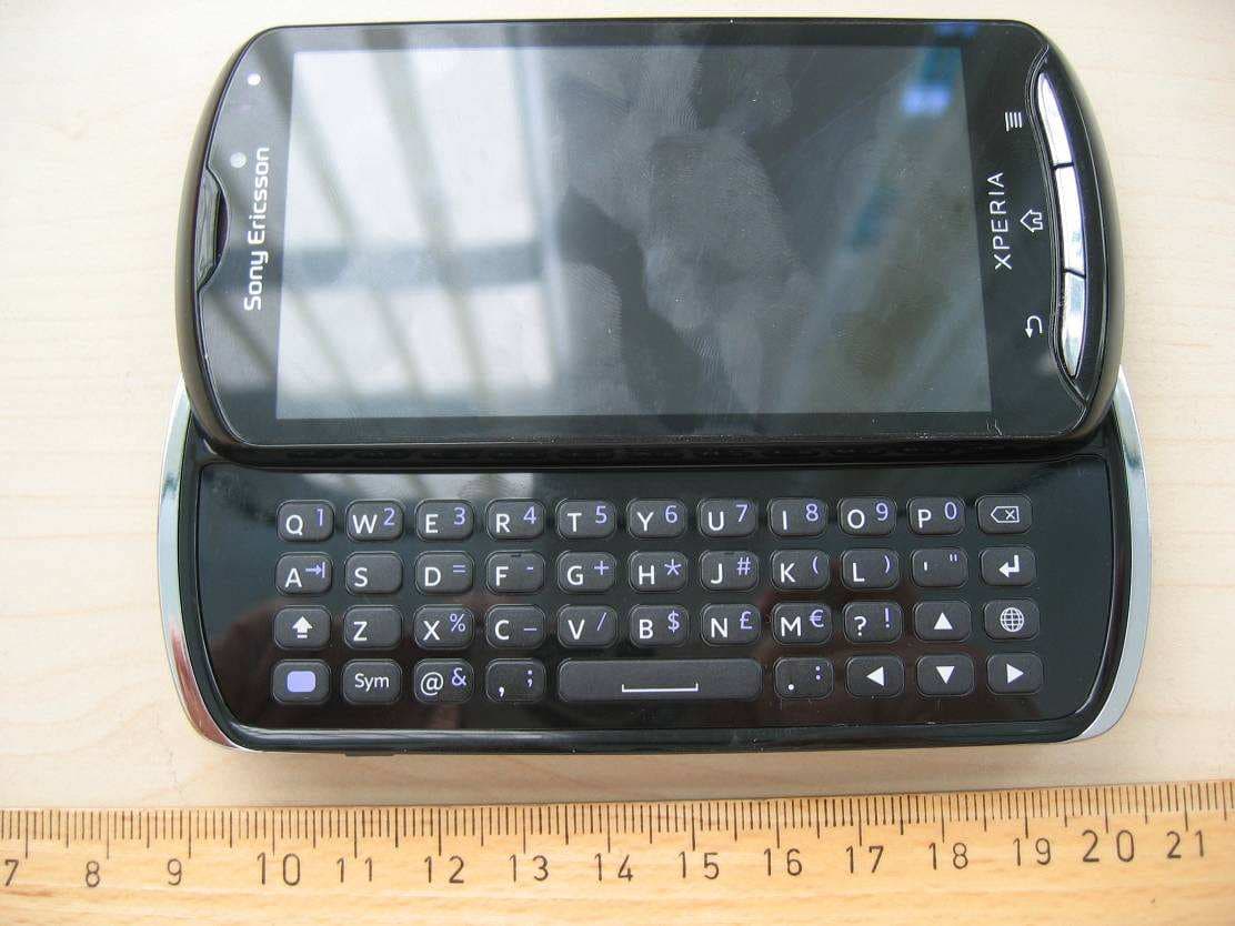
Click to zoom
Application Details
- Equipment Class
- DXX - Part 15 Low Power Communication Device Transmitter
- Date of Grant
- Jul 18, 2011
- Application Purpose
- Original Equipment
- Date of Application
- Jul 18, 2011
- Equipment Note
- Mobile phone with Bluetooth, WLAN 802.11bgn, GPS/A-GPS, ANT+ and FM Rx
- Frequency Range
- 2402.00000000 - 2480.00000000
- Company
- Sony Corporation
- Country
- Japan
Documents & Files
Document Text
Text extracted from the exhibit documents filed with the FCC. Open a document above to read the original.
Users Manual
pro Startup guide Sony Ericsson Mobile Communications AB SE-221 88 Lund, Sweden www.sonyericsson.com 1245-2926.1 Welcome Digital User guide This Startup guide is aimed at getting you through the first hour of using your new phone. As part of our Greenheart™ initiatives, we have placed a full-length User guide in the phone and on the web. By keeping the full User guide in digital format, we have cut down substantially on the amount of paper we print. You can find more information on how to access the in-phone User guide and other support at the end of this Startup guide. Important information Please read the Important information leaflet before you use your mobile phone. Assembly To remove the battery cover To insert the SIM card and the battery S I XXXX-XXX X TYPE: AAD- 3880110 -B V IC : 417 0 B-A 3880 11 0 F CC ID: PY7A 3880 11 0 R yy W w w XXXyy W ww F F GG S/ N: XXXAB C 1234 Made i n X x x MK1 6i 0000000 - 000000 - 0 To attach the battery cover Phone basics Phone overview 2 1 57 4 6 8 9 3 1918 20 10 11 16 15 13 14 12 17 1. Connector for charger/USB cable 2. Front camera 3. Light sensor 4. Touch screen 5. Menu key 6. Home key 7. Back key 8. Slideout keyboard 9. Ear speaker 10. Headset connector 11. Power key 12. Strap hole 13. Speaker 14. Camera key 15. Volume key/Zoom key 16. HDMI connector 17. Notification LED/ Battery status 18. Camera lens 19. Camera LED flash 20. Second microphone Turning on the phone To turn on the phone To enter your SIM card PIN code • Tap the numbers on the screen to enter the personal identification number (PIN) for your SIM card. Waking up the screen To activate the screen • Press or press briefly. To unlock the screen • Drag the icon to the right across the screen. Using the hardware keys Back • Go back to the previous screen • Close the on-screen keypad, a dialog box, an options menu, or the Notification panel Home • Go to the Home screen or to the Application screen from any application or screen • Press and hold to open a window showing your most recently used applications Menu • Open a list of options available in the current screen or application Using the touch screen To open or highlight an item • Tap the item. To scroll • Drag or flick your finger in the direction you want to scroll on the screen. To zoom with two fingers • Place two fingers on the screen at once and pinch them together (to zoom out) or spread them apart (to zoom in). Typing text Use one of the following methods to type text containing letters, numbers and other characters: • Slide-out keyboard • On-screen keyboard • Phonepad When you are using the slide-out keyboard, the on-screen input methods become unavailable. Using the slide-out keyboard 1 2 3 4 7 8 9 5 6 1Change the character case and turn on the caps lock. For some languages, this key is used to access extra characters in the language. 2Mode toggle key – Press here to activate associated keys featuring characters of the same colour. For example, press this key once and then press the "Q" key to enter "1". 3Display symbols and smileys 4Enter a space 5Navigate left and right within a text field, or among other word and character options 6Navigate up and down within a text field, across rows, or among other word and character options 7Open the text input settings menu to change, for example, the Writing languages. 8Enter a carriage return or confirm text input 9Delete a character before the cursor All illustrations are for illustration purposes only and may not accurately depict the actual phone. Type & Send Use the Type & Send widget as a clipboard for typing text. First type some text and then decide what to do with it. For example, you can decide to send it as a text message, an email or a Facebook™ post. To use the Type & Send widget 1 From your Home screen, scroll left or right to find the Type & Send widget. The widget should be displayed at the top of the screen. 2 Slide out the keyboard and type some text in the text entry field using the keyboard keys. 3 After you type your text , tap , select a sending method, and then follow the on-screen instructions. 4 To use your text in a search, tap and select a search engine. Set up your phone The first time you start your phone, a setup guide explains basic phone functions and helps you enter essential settings. You can also access the setup guide later. To access the setup guide 1 From the Home screen, tap . 2 Tap Setup guide. Android™ – what and why? An Android™ phone is based on an open source platform, and is pre-loaded with Google™ services. To make the best out of any provided Google™ services, you should create a Google™ account and sign in to it when you first start your phone. With the account, you can extend the functionality of the phone by downloading applications and games from a constantly growing collection at Android Market™. You need to have Internet access for many of the features in Android. Accounts and services Use online services in your phone. Sign in with your existing account or sign up and create an account. Google™ account Use Gmail™ to send emails, Google Talk™ to chat with friends, and Android Market™ to download applications. Sony Ericsson account Store your phone contacts on a secure Sony Ericsson server, and you'll always have a backup online. Exchange Active Sync account Synchronise your phone with your corporate Exchange Active Sync account. This way, you keep your work email, contacts and calendar events with you at all times. To add an account 1 From your Home screen, tap . 2 Tap Settings > Accounts & sync > Add account. 3 Tap the account type you want to add and then follow the registration wizard. Getting contacts into your phone The first time you open the Contacts application, you get hints on how to start adding contacts to your phone. This is a good time to choose a method that suits your situation and setup. View all import options on www.sonyericsson.com/support/ contacts. Here are two recommended options: Synchronise your phone with…
Text truncated - open the document above for the full version.
Cover Letter(s)
Sony Ericsson Confidentiality Request 2011-07-08 CVDVBA11 :318 SEMC/CVDVBA Afrah Sadiq +46 108012250 Receiver Federal Communications Commission Subject: Request for Confidentiality FCC ID: PY7A3880110 To Whom It May Concern: In accordance with §0.459 of CFR 47, Sony Ericsson Mobile Communications AB requests confidentiality for the below listed items for our mobile phone type AAD 3880110-BV, FCC ID: PY7A3880110: 1. Block Diagram 2. Schematic Diagram 3. Part List 4. OperationalfTechnical Descriptions These items contain detailed system and equipment description and related information about the product which Sony Ericsson Mobile Communications AB considers to be proprietary, confidential and a custom design which otherwise would not be released to the general public. Since this design is a basis from which future technological products will evolve, Sony Ericsson Mobile Communications AB also feels that this information would be of benefit to its competitors, and that the disclosure of the information in these exhibits would give our competitors an unfair advantage in the market. Please contact the undersigned if there are any further questions or additional information needed in this matter. Afrah Sadiq Staff Verification Engineer Global Type Approval Sony Ericsson Mobile Communications Nya Vattentornet 221 88 Lund, Sweden Fax: +46108002441 sOllyericsson .com Sony Ericsson Mobile Communications AB Styrelsens sate: Lund Momsnr. II.A. TNo: SE556615665801 Registered office: Lund Organisationsnr • Reg No: 556615-6658 Postadress • Mail Besoksadress • Office address Telelon • Telephone Telelax • Telelax SE-221 88 Lund Sweden Nya Vattentornet Lund Nat Int 010-80 00000 +46 10 80 00000 Nat Int 010-80 02040 +46 10 80 02040
External Photos
Annex to Test Report No.: 1-2977-29-02/11 2011-05-10 Page 18 of 29 An ne x B E x te rna l ph ot ogra phs o f the E UT Photo documentation Photo 4: Annex to Test Report No.: 1-2977-29-02/11 2011-05-10 Page 19 of 29 Photo 5: Photo 6: Annex to Test Report No.: 1-2977-29-02/11 2011-05-10 Page 20 of 29 Photo 7: Photo 8: Annex to Test Report No.: 1-2977-29-02/11 2011-05-10 Page 21 of 29 Photo 9: Photo 10: Annex to Test Report No.: 1-2977-29-02/11 2011-05-10 Page 22 of 29 Photo 11:
ID Label/Location Info
1 (2) Company Internal MARKING DRAWI NG Prepared (also subject responsible if other) No. SEM/CVVGP, Anna Englund 1245-4112 Uen Approved Checked Date Rev Reference SEM/CVVGP, Anna Englund 2011-03-07 1 5 MK16i, Mobile Phone label, ROW, Made in... 1 General information Mobile Phone label part no 1243-4091 Mobile Phone label content part no 1245-4111 Bar code Print quality: according to COSMETIC GUIDELINE – Bar code labels document 1222-6072 Uen Quiet zone: No bar codes are allowed to be closer to a label edge than 4 mm! Text If applicable, or nothing else specified, Zebra printer Scaleable Smooth Font CG Triumvirate Bold Condensed is imposed. When needed, the text is adjusted to fit the label. Coordinates “(x/y)” under each line number specifies the bottom / left alignment for text, graphics and bar codes, x is measured vertically, and y horizontally from the upper left corner of the label (landscape format), both in mm. When needed, the alignment is adjusted to fit the label. MLCI= Main Label Content Information Document 2 Printing information Content Format Line 1 (7,0/36,0) Micro SD logo Graphics height 5,2 mm acc to 1247-1508 (microSD logo) Line 2 (10,0/10,0) SIM-card logo Graphics height 7,0mm acc to 1001-4476, rotated 180 degrees Line 3a (12,0/5,0) Sony Ericsson stylized name. Graphics, height 1,5 mm. According to 1200-1925 Line 3b (12,0/23,0) Model Name “MK16i” Text, height 1,2 mm. According to Chapter 1 in MLCI. Line 4a (14,0/5,0) Product number of the Sales Item in which the phone is packed, if applicable. “SI XXXX-XXXX” Text, height 1,2 mm. Line 4b (14,0/23,0) Location code of where the phone is flashed, if applicable, “XXX” Text, height 1,2 mm. Line 5a (17,0/5,0) “TYPE: AAD-3880110-BV” Text, height 1,2 mm. According to Chapter 1 in MLCI. Line 5b (17,0/23,0) HW & SW identification field, if applicable; “FFGG” Text, height 1,2 mm. According to Type-testing report under Product Model Specifying Documents Line 6a (14,0/5,0) ”FCC ID: PY7A3880110” Text, height 1,2 mm. According to Chapter 1 in MLCI. Line 6b (14,0/23,0) Production week (flash), “yyWww” (yy = year, ww = week) Text, height 1,2 mm. Line 7a (21,0/5,0) “IC: 4170B-A3880110” Text, height 1,2 mm. According to Chapter 1 in MLCI. Line7b (21,0/23,0) Repair week, if applicable. “RyyWww” (yy = year, ww = week) Text, height 1,2 mm. Company Internal MARKING DRAWING 2 (2) Prepared (also subject responsible if other) No. SEM/CVVGP, Anna Englund 1245-4112 Uen Approved Checked Date Rev Reference SEM/CVVGP, Anna Englund 2011-03-07 1 5 Line 8 (26,0/6,0) Line 10 in bar code, according to line 9a. As desired by supplier (e.g. only actual number). Bar code, height 2,0 mm. As desired by supplier (e.g. Code 128 symbology). Line 9a (28,0/5,0) Supplier’s identification for trace-ability of the telephone, as desired by supplier (e.g. “S/N: nnn....” for serial number). Text, height 1,5 mm. Defined by supplier. Line 9b (28,0/20,0) Actual electronic serial number (IMEI) of the mobile phone, “00000000-000000-0” Text, height 1,5mm. In the format TAC-SNR-CD. TAC and SNR derived from pos 500 in BOM. CD = check digit according to the Luhn formula (ISO/IEC 7812), GSM 02.16. Line 10 (31,0/6,0) Line 10 in bar code, according to line 9b. As desired by supplier (e.g. only actual number). Bar code, height 2,0 mm. As desired by supplier (e.g. Code 128 symbology). Line 11a (37,0/5,0) CE approval symbol, the NB-“0682” and “Alert Symbol” in one artwork Graphics, height 5 mm. According to 1242-7470 Line 11b (37,0/38,0) WEEE trashcan without bar symbol Graphics, min. height 5mm, according to 1202-5537. Line 12 (41,0/5,0) Marking of origin; “Made in Xxx” “Xxx” = actual country of production of the included telephone, in English Text, height 1,2 mm. 3 Layout The conceptual picture (for Zebra 90XiII printer, or equivalent) should not be considered as specifications, but as an additional help for setting up the label. 3.1 Conceptual picture double underlined = major changes since last revision. Confidential MARKING DRAWING 1(1) Document number R evision 1245-4112 Uen Prepared by Date 2011- 03-07 Contents responsible if other than preparer Remarks This document is managed in metaDoc. Approved by Note: Any hard copy of this document is for reference only. D ue to template and application dependencies the header and footer may fail to display correct data. It is the responsibility of the user to ensure that they have a correct and valid version. Any outdated hard copy is invalid and must be removed from possible use. Label placement To find the label follow these steps: 1 . Remove the cover on the rear side of the product. 2. Remove the battery. 3. The label is located behind the battery. Rear side of the phone Place for battery Label placement
Internal Photos
Annex to Test Report No.: 1-2977-29-02/11 2011-05-10 Page 23 of 29 An ne x C Inte r na l p ho to gra phs o f the E UT Photo documentation Photo 12: Annex to Test Report No.: 1-2977-29-02/11 2011-05-10 Page 24 of 29 Photo 13: Photo 14: Annex to Test Report No.: 1-2977-29-02/11 2011-05-10 Page 25 of 29 Photo 15: Photo 16: Annex to Test Report No.: 1-2977-29-02/11 2011-05-10 Page 26 of 29 Photo 17: Photo 18: Annex to Test Report No.: 1-2977-29-02/11 2011-05-10 Page 27 of 29 Photo 19: Photo 20: Annex to Test Report No.: 1-2977-29-02/11 2011-05-10 Page 28 of 29 Photo 21: Annex to Test Report No.: 1-2977-29-02/11 2011-05-10 Page 29 of 29 An ne x D Doc u me n t his to r y Version Applied changes Date of release 1.0 Initial release 2011-05-10 An ne x E Fur the r in for ma ti o n Glossary DUT - Device under Test EMC - Electromagnetic Compatibility EUT - Equipment under Test FCC - Federal Communication Commission FCC ID - Company Identifier at FCC HW - Hardware IC - Industry Canada Inv. No. - Inventory number N/A - not applicable S/N - Serial Number SW - Software
Test Report
Page 1 of 29 The test results relate only to the individual items which have been tested. This report shall not be reproduced in parts without the written approval of the testing laboratory © Copyright: All rights reserved by CETECOM Laboratory Accreditation and Listings Reg. No.: 736496 MRA US-EU 0003 Industry Canada Reg. No.: 3462D-1 Reg. No.: 3462D-2 Voluntary Controls for Electromagnetic Emissions Reg. No.: R-2665, R-2666 C-2914, T-1967, G-301 accredited according to DIN EN ISO/IEC 17025 CETECOM GmbH Laboratory Radio Communications & Electromagnetic Compatibility Im Teelbruch 116 • 45219 Essen • Germany Registered in Essen, Germany, Reg. No.: HRB Essen 8984 Tel.: + 49 (0) 20 54 / 95 19-954 • Fax: + 49 (0) 20 54 / 95 19-964 E-mail: [email protected] • Internet: www.cetecom.com TEST REPORT No.: 2-20797620g/11 for Mobile phone AAD-3880110-BV FCC-ID: PY7A3880110 IC: 4170B-A3880110 According to: FCC Regulations Part 15 B & Part 15.249(a)(c)(d)(e) IC Regulations RSS-Gen, Issue 3 RSS-210: Issue 8 Sony Ericsson Mobile Communications AB Test Report 2-20797620g/11, Page 2 of 29 TR_2_20797620g_11.doc Table of contents 1. SUMMARY OF TEST RESULTS...................................................................................................................... 3 1.1. TESTS OVERVIEW FCC and Canada IC Standards (RSS) .................................................................... 3 2. ADMINISTRATIVE DATA ............................................................................................................................... 5 2.1. Identification of the testing laboratory ............................................................................................................. 5 2.2. Test location .................................................................................................................................................... 5 2.3. Organizational items ........................................................................................................................................ 5 2.4. Applicant’s details ........................................................................................................................................... 5 2.5. Manufacturer’s details ..................................................................................................................................... 5 3. EQUIPMENT UNDER TEST (EUT) ................................................................................................................. 6 3.1. EUT: Type, S/N etc. and short descriptions used in this test report ................................................................ 6 3.2. Auxiliary Equipment (AE): Type, S/N etc. and short descriptions .................................................................. 6 3.3. EUT set-ups ..................................................................................................................................................... 7 3.4. Configuration of cables used for testing .......................................................................................................... 7 3.5. EUT operating modes .................................................................................................................................... 7 4. DESCRIPTION OF TEST SET-UP’S ................................................................................................................ 8 4.1. Test set-up for radiated measurements ............................................................................................................ 8 5. MEASUREMENTS ............................................................................................................................................. 10 5.1. Radiated field strength emissions below 30 MHz .......................................................................................... 10 5.2. Radiated field strength emissions, 30 MHz - 1 GHz ....................................................................................... 12 5.3. Radiated emissions, above 1 GHz ................................................................................................................... 15 5.4. 6-dB Bandwidth FCC 15.247, RSS-210 ....................................................................................................... 21 5.5. Band-Edge compliance measurements, FCC 15.205/15.209, RSS-210 ...................................................... 23 5.6. Measurement uncertainties .............................................................................................................................. 24 6. INSTRUMENTS AND ANCILLARY ................................................................................................................ 25 6.1. Used equipment “CTC” ................................................................................................................................... 25 7. CORRECTION FACTORS DUE TO REDUCED MEAS. DISTANCE (F< 30 MHZ) ................................ 29 Table of annex Total pages DOCUMENT TR_2_20797620G_11_A1: MEASUREMENT DIAGRAMS 28 DOCUMENT TR_2_20797620G_11_A2: PHOTOS OF MEASUREMENT SET-UP 3 Test Report 2-20797620g/11, Page 3 of 29 TR_2_20797620g_11.doc 1. Summary of test results The test results apply exclusively to the test samples as presented in chapter 3.1. The CETECOM GmbH does not assume responsibility for any conclusions and generalizations taken in conjunction with other specimens or samples of the type of the item presented to tests. The presented EUT is a mobile phone with integrated ANT+ wireless technology and integral antenna. Other wireless technologies were not considered within this test report. Following tests have been performed to show compliance with applicable FCC Part 2 and Part 15 rules of the FCC CFR 47 (2010-1-09 Edition) and Industry Canada RSS-210, Issue 8 and RSS-Gen, Issue 3 regulations. 1.1. TESTS OVERVIEW FCC and Canada IC Standards (RSS) TEST CASES PORT REFERENCES &…
Text truncated - open the document above for the full version.
Test Report
Page 1 of 28 The test results relate only to the individual items which have been tested. This report shall not be reproduced in parts without the written approval of the testing laboratory © Copyright: All rights reserved by CETECOM Annex 1: Measurement diagrams to TEST REPORT No.: 2-20797620g/11 for Mobile phone AAD-3880110-BV FCC-ID: PY7A3880110 IC: 4170B-A3880110 Laboratory Accreditation and Listings Reg. No.: 736496 MRA US-EU 0003 Industry Canada Reg. No.: 3462D-1 Reg. No.: 3462D-2 Voluntary Controls for Electromagnetic Emissions Reg. No.: R-2665, R-2666 C-2914, T-1967, G-301 accredited according to DIN EN ISO/IEC 17025 CETECOM GmbH Laboratory Radio Communications & Electromagnetic Compatibility Im Teelbruch 116 • 45219 Essen • Germany Registered in Essen, Germany, Reg. No.: HRB Essen 8984 Tel.: + 49 (0) 20 54 / 95 19-954 • Fax: + 49 (0) 20 54 / 95 19-964 E-mail: [email protected] • Internet: www.cetecom.com According to: FCC Regulations Part 15 Part B Part 15.249 (a)(c)(d)(e) IC Regulations RSS-Gen, Issue 3 RSS-210: Issue 8 Sony Ericsson Mobile Communications AB Annex 1 to Test Report 2-20797620g/11, Page 2 of 28 TR_2_20797620g_11_A1.doc Table of contents 1. MEASUREMENT DIAGRAMS ......................................................................................................................... 3 1.1. 6dB bandwidth ................................................................................................................................................. 3 1.2. 99% Occupied bandwidth ................................................................................................................................ 4 1.3. Radiated field strength (15.209/RSS-Gen.) ..................................................................................................... 5 1.3.1. Radiated magnetic field strength measurements (f<30MHz) 5 1.3.2. Radiated field strength (30MHz < f < 1GHz) 8 1.3.3. Radiated field strength (1GHz < f < 18GHz) 11 1.3.4. Radiated field strength (18GHz < f < 25GHz) 17 1.3.5. Carrier radiated field strength in 3m distance and band-edge compliance radiated according FCC §15.205 & §15.209 19 1.4. Radiated field strength (§15.109, Class B and RSS-Gen) ............................................................................... 26 1.4.1. Radiated field strength (30MHz < f < 1GHz) 26 1.4.2. Radiated field strength (1GHz < f < 12.75GHz) 27 Annex 1 to Test Report 2-20797620g/11, Page 3 of 28 TR_2_20797620g_11_A1.doc 1. Measurement diagrams 1.1. 6dB bandwidth Att 5 dB 2.401984423 GHz A 2.401984423 GHz Ref-35 dBm 2.401984423 GHz Center2.402026923 GHz 2.401984423 GHz Span1 MHz 2.401984423 GHz 100 kHz/ 2.401984423 GHz * 2.401984423 GHz * 2.401984423 GHz RBW 50 kHz 2.401984423 GHz VBW 1 MHz 2.401984423 GHz SWT 45 ms 2.401984423 GHz 1 PK 2.401984423 GHz VIEW 2.401984423 GHz 2.401984423 GHz 2.401984423 GHz 2.401984423 GHz 2.401984423 GHz 2.401984423 GHz 2.401984423 GHz 2.401984423 GHz 2.401984423 GHz 2.401984423 GHz -75 -70 -65 -60 -55 -50 -45 -40 -35 2.401984423 GHz 1 Marker 1 [T1 ] -42.83 dBm 2.401768077 GHz 2 Delta 2 [T1 ] -0.16 dB 435.897435897 kHz 3 Marker 3 [T1 ] -36.82 dBm 2.401984423 GHz D1 -42.82 dBm MARKER 3 2.401984423 GHz Date: 22.JUN.2011 14:37:03 Channel 1 Annex 1 to Test Report 2-20797620g/11, Page 4 of 28 TR_2_20797620g_11_A1.doc 1.2. 99% Occupied bandwidth Att 5 dB 2.440979446 GHz A 2.440979446 GHz 2.440979446 GHz 2.440979446 GHz 2.440979446 GHz 2.440979446 GHz 2.440979446 GHz 2.440979446 GHz 2.440979446 GHz 2.440979446 GHz 2.440979446 GHz SGL 2.440979446 GHz * 2.440979446 GHz 1 RM 2.440979446 GHz MAXH 2.440979446 GHz Ref-30 dBm 2.440979446 GHz Center2.441063846 GHz 2.440979446 GHz Span2 MHz 2.440979446 GHz 200 kHz/ 2.440979446 GHz * 2.440979446 GHz RBW 50 kHz 2.440979446 GHz VBW 500 kHz 2.440979446 GHz SWT 60 s 2.440979446 GHz * 2.440979446 GHz -90 -85 -80 -75 -70 -65 -60 -55 -50 -45 -40 -35 -30 2.440979446 GHz 1 Marker 1 [T1 ] -37.56 dBm 2.440979446 GHz OBW864.400000000 kHz T1 Temp 1 [T1 OBW] -56.05 dBm 2.440555046 GHz T2 Temp 2 [T1 OBW] -56.24 dBm 2.441419446 GHz MARKER 1 2.440979446 GHz Date: 22.JUN.2011 14:49:27 Channel 39 Annex 1 to Test Report 2-20797620g/11, Page 5 of 28 TR_2_20797620g_11_A1.doc 1.3. Radiated field strength (15.209/RSS-Gen.) 1.3.1. Radiated magnetic field strength measurements (f<30MHz) Diagram No. g_3.01 Common Information Test description: Magnetic Fieldstrength Measurement Test site and distance: Semi Anechoic Room (SAR) + mobile floor absorbers and 3m measurement distance Measured sides of EUT: front, right, rear, left Rec. antenna (pre-scan): height 1.00 m, parallel and 90° to EUT polarisation Turntable step: 90° during pre-scan Used filter: bypass Test specification.: FCC 15.205 § 15.209; RSS-Gen: Issue 3 Operator: TAS Operating conditions: TX-on Power during tests: full loaded batteries Comment 1: Channel low EUT Name: AAD-3880110-BV Manufacturer: Sony Ericsson Comment: S/N ....CHYCC, ANT+ technology Accessories -- EUT Information EUT Name: AAD-3880110-BV Manufacturer: Sony Ericsson Comment: S/N ....CHYCC, ANT+ technology EUT Name: AAD-3880110-BV Manufacturer: Sony Ericsson Comment: S/N ....CHYCC, ANT+ technology -1 00 -9 0 -8 0 -7 0 -6 0 -5 0 -4 0 -3 0 -2 0 -1 0 0 10 20 30 40 50 9k203050100 k2003005001M2M3M5M10M2030M Level in dBμV/m Frequency in H z FCC15.209_magn hor+vert FCC15.209_Magnetic_Field FCC15.209_AV_2 19,820000 MH z 14,958 dBμV/m EMI Auto Test Template: FCC15.209_magn hor+vert Annex 1 to Test Report 2-20797620g/11, Page 6 of 28 TR_2_20797620g_11_A1.doc Diagram No. g_3.02 Common Information Test description: Magnetic Fieldstrength Measurement Test site and distance: Semi Anechoic Room (SAR) + mobile floor absorbers and 3m measurement distance Measured sides of EUT: front, right, rear, left Rec. antenna (pre-scan): height 1.00 m, parallel and 90° to EUT polarisation Turntable step: 90° during pre-scan Used filter: bypass Test specification.: FCC 15.205 § 15.209; RSS-Gen: Issue 3 Operator: TAS Operating conditions: TX…
Text truncated - open the document above for the full version.
Test Setup Photos
Page 1 of 3 The test results relate only to the individual items which have been tested. This report shall not be reproduced in parts without the written approval of the testing laboratory © Copyright: All rights reserved by CETECOM Annex 2: Photos of measurement set-up to TEST REPORT No.: 2-20797620g/11 for Mobile phone AAD-3880110-BV FCC-ID: PY7A3880110 IC: 4170B-A3880110 Laboratory Accreditation and Listings Reg. No.: 736496 MRA US-EU 0003 Industry Canada Reg. No.: 3462D-1 Reg. No.: 3462D-2 Voluntary Controls for Electromagnetic Emissions Reg. No.: R-2665, R-2666 C-2914, T-1967, G-301 accredited according to DIN EN ISO/IEC 17025 CETECOM GmbH Laboratory Radio Communications & Electromagnetic Compatibility Im Teelbruch 116 • 45219 Essen • Germany Registered in Essen, Germany, Reg. No.: HRB Essen 8984 Tel.: + 49 (0) 20 54 / 95 19-954 • Fax: + 49 (0) 20 54 / 95 19-964 E-mail: [email protected] • Internet: www.cetecom.com According to: FCC Regulations Part 15 Part B Part 15.249 (a)(c)(d)(e) IC Regulations RSS-Gen, Issue 3 RSS-210: Issue 8 Sony Ericsson Mobile Communications AB Annex 2 to Test Report 2-20797620g/11, Page 2 of 3 TR_2_20797620g_11_A2.doc Table of contents 1. PHOTOS OF MEASUREMENT SET-UP......................................................................................................... 3 Annex 2 to Test Report 2-20797620g/11, Page 3 of 3 TR_2_20797620g_11_A2.doc 1. Photos of measurement set-up Measurements in anechoic-chamber
Contact Information
Applicant
Mika Kaneko(Chief Regulatory Compliance Manager)
Technical Contact
Sony Ericsson Mobile Communications ABH�kan Sj�berg
Nya Vattentornet · Lund · Sweden
Test Firm
Cetecom ICT Services GmbHRalf Hoehn
Technical Specifications
| # | Rule Parts | Frequency Range | Power Output |
|---|---|---|---|
| 1 | 15C | 2.40 GHz - 2.48 GHz | - |
Other Applications from Sony Corporation
PY7-75158T
Jul 16, 2026GSM/WCDMA/LTE Phone with BT, DTS/UNII a/b/g/n/ac/ax, NFC and GNSS
Equipment Class
NII - Unlicensed National Information Infrastructure TXPY7-52715J
Jul 16, 2026GSM/WCDMA/LTE Phone with BT, DTS/UNII a/b/g/n/ac/ax, NFC and GNSS
Equipment Class
DXX - Part 15 Low Power Communication Device TransmitterPY7-84526Y
Jul 16, 2026GSM/WCDMA/LTE Phone with BT, DTS/UNII a/b/g/n/ac/ax, NFC and GNSS
Equipment Class
PCE - PCS Licensed Transmitter held to earPY7-30515Z
Apr 13, 2026GSM/WCDMA/LTE/NR Phone with BT, DTS/UNII a/b/g/n/ac/ax/be, NFC, GNSS and WPT
Equipment Class
DXX - Part 15 Low Power Communication Device TransmitterPY7-73716J
Apr 11, 2024GSM/WCDMA/LTE Phone with BT, DTS/UNII a/b/g/n/ac, NFC and GNSS
Equipment Class
PCE - PCS Licensed Transmitter held to ear