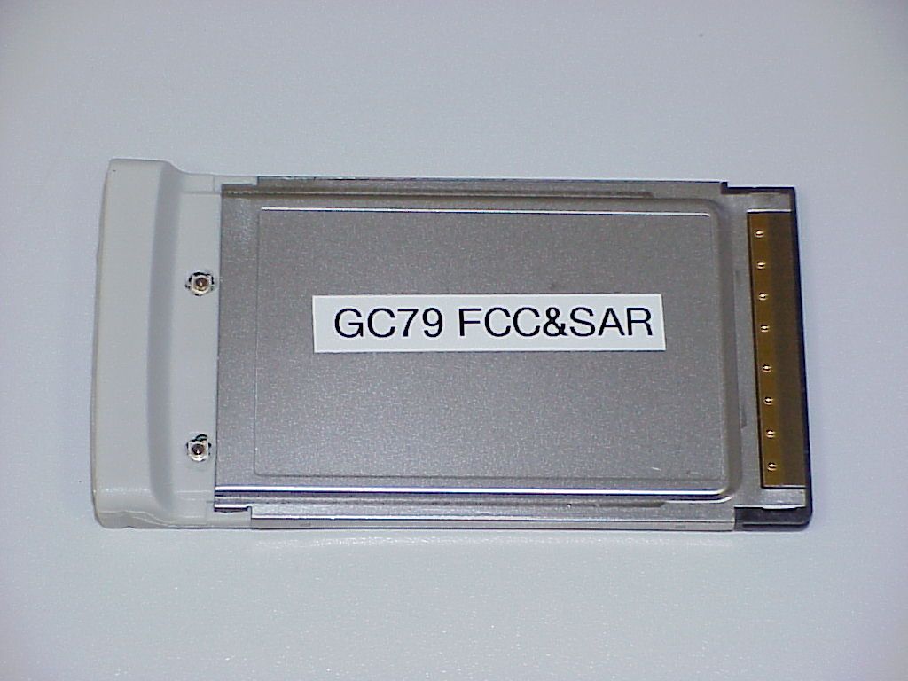
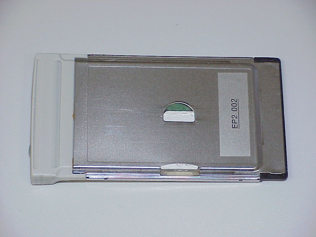
PY7F1021011GSM/GPRS and WLAN Combo card
Sony Corporation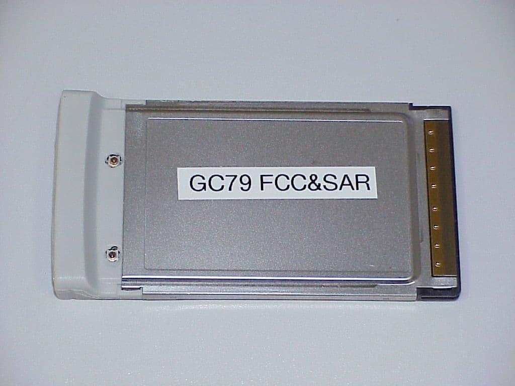
Click to zoom
Application Details
- Equipment Class
- PCB - PCS Licensed Transmitter
- Date of Grant
- Jul 30, 2003
- Application Purpose
- Original Equipment
- Date of Application
- May 27, 2003
- Equipment Note
- GSM/GPRS and WLAN Combo card
- Frequency Range
- 1850.20000000 - 1909.80000000
- Company
- Sony Corporation
- Country
- Japan
Documents & Files
Document Text
Text extracted from the exhibit documents filed with the FCC. Open a document above to read the original.
Users Manual
Broadcom Corporation Declaration of Conformity for the Project FAE - 1021011-BV July 14, 2003 Dipl.-Ing. Ahmet Kilic Broadcom Corportion 190 Mathilda Place Sunnyvale, CA 94086 USA +1 408 543 3300 Broadcom Corporation Declaration of Conformity for the Project FAE – 1021011-BV Confidential Page 2 of 2 7/14/2003 This confidential document is the property of Broadcom Corporation and may not be copied or circulated without permission Broadcom Corporation 190 Mathilda Place Sunnyvale, Ca 94086 USA July 14, 2003 Declaration of Conformity We, Broadcom Corporation, hereby declare that the functionality of the GC79 PCMCIA Card is the same as the Mini PCI. Yours truly, Ahmet Kilic Contents: Broadcom BCM94306MP Internal 802.11b Mini PCI Card User's Guide Broadcom BCM94306MP Internal 802.11b Mini PCI Card User's Guide Introduction Completing the Setup Using the Broadcom BCM94306MP Wireless Utility Specifications Regulatory Information Troubleshooting Glossary Information in this document is subject to change without notice. © Copyright 2002 Broadcom Corporation. All rights reserved. This document is protected by copyright and distributed under licenses restricting its use, copying, distribution, and decompilation. No part of this document may be reproduced in any form by any means without prior written authorization of Broadcom Corporation. Documentation is provided "as is" without warranty of any kind, either express or implied, including any kind of implied or express warranty of non-infringement or the implied warranties of merchantability or fitness for a particular purpose. Broadcom Corporation reserves the right to make changes without further notice to any products or data herein to improve reliability, function, or design. Information furnished by Broadcom Corporation is believed to be accurate and reliable. However, Broadcom Corporation does not assume any liability arising out of the application or use of this information, nor the application or use of any product or circuit described herein, neither does it convey any license under its patent rights nor the rights of others. Broadcom, the pulse logo, and Connecting Everything are trademarks of Broadcom Corporation and/or its subsidiaries in the United States and certain other countries. Microsoft, Windows XP, and Windows 2000 are registered trademarks of Microsoft Corporation. All other trademarks are the property of their respective owners. Broadcom Corporation disclaims any proprietary interest in trademarks and trade names other than its own. Restrictions and Disclaimers The information contained in this document, including all instructions, cautions, and regulatory approvals and certifications, is provided by the supplier and has not been independently verified or tested by Broadcom. Broadcom cannot be responsible for damage caused as a result of either following or failing to follow these instructions. All statements or claims regarding the properties, capabilities, speeds or qualifications of the part referenced in this document are made by the supplier and not by Broadcom. Broadcom specifically disclaims knowledge of the accuracy, completeness or substantiation for any such statements. All questions or comments relating to such statements or claims should be directed to the supplier. Preliminary Release: November 2002 94306MP-UM100-D1 file:///P|/pc/My%20Documents/Working/User%20Guides/94306MP/Index.htm [11/22/2002 2:16:03 PM] Introduction: Broadcom BCM94306MP Mini PCI Card User's Guide Back to Contents Introduction: Broadcom BCM94306MP Mini PCI Card User's Guide Before you begin Things you should know BCM94306MP network Before you begin Obtain the following information from your network administrator (if you are a home user, obtain this information from the person that installed your wireless access point): l Network names (SSID) of the specific wireless networks that you want to connect to. l WEP (Wired Equivalent Privacy) key information (if any) for the networks you want to connect to. l For Microsoft® Windows® networking, your customer name and workgroup name. l For your network account, your user name and password. l Your IP address (if not using a DHCP server) Things you should know When you start your computer, your Broadcom BCM94306MP internal 802.11b Mini PCI card detects certain wireless networks that are within range. Before you can connect to these and other wireless networks, you must configure a profile for each network using the information you obtained from your network administrator. Instructions for configuring a network profile are provided in Completing the setup. WEP is a security protocol for wireless local area networks (defined in the IEEE 802.11b standard) that encrypts data sent over radio waves. The use of the WEP key is optional and can be enabled or disabled. If the network you are connecting to has enabled WEP, you must also enable WEP in the network profile and set the WEP key to match the WEP key used by the network. Otherwise, you cannot connect to the network. Broadcom BCM94306MP network The Broadcom BCM94306MP solution allows you to make a wireless connection to a network, as illustrated below. file:///P|/pc/My%20Documents/Working/User%20Guides/94306MP/intro.htm (1 of 2) [11/22/2002 2:16:04 PM] Introduction: Broadcom BCM94306MP Mini PCI Card User's Guide Back to top Back to Contents Please read copyright and trademark information. file:///P|/pc/My%20Documents/Working/User%20Guides/94306MP/intro.htm (2 of 2) [11/22/2002 2:16:04 PM] Completing the Setup: Broadcom BCM94306MP Mini PCI Card User's Guide Back to Contents Completing the Setup: Broadcom BCM94306MP Mini PCI Card User's Guide NOTE—Before you begin, be sure you have the required network information from your network administrator (see Before you begin in the Introduction section). Configuring a network profile (Windows® 2000 environment) Configuring a network profile (Windows® XP environment) Configuring a network profile (Windows® 2000 envir…
Text truncated - open the document above for the full version.
Users Manual
Welcome to the GC75 Manager The GC75 Manager controls the GC75 PC Card and provides the following functions: zStartup and shutdown the GC75 PC Card's radio transmitter zDefinition of network connections over CSD/HSCSD and GPRS zConnect to and disconnect from the internet or corporate network zGSM settings such as network service provider, call diversion and call barring zSend and receive SMS Text Messages zManagement of the SIM Phone Book When the GC75 Manager is activated, the GC75 Manager icon is shown in the taskbar at the bottom right corner of your computer screen. See also: GC75 Manager Icon Dial -Up Networking Icon PC Card Icon GC75 Manager Icon The GC75 Manager icon is shown in the taskbar when the GC75 Manager is running. In the following example, the GC75 Manager icon appears to the left of the time-of-day clock: The GC75 Manager icon will indicate if a GC75 PC card is inserted as well as the GSM/GPRS service status and connection state. The GC75 Manager icon shows the following states: Right click on the GC75 Manager icon to view the GC75 Manager Menu . To close the GC75 Manager, select The radio transmitter is in the power off (disabled) state. The radio transmitter is on, but there is no GSM or GPRS service available. The GC75 has GSM service and indicates a signal strength of 3 out of 5 bars. CSD/HSCSD, SMS and FAX may be used, provided these are supported by the subscription. GPRS is not available. The GC75 has GSM and GPRS service. Page 1 of 5Welcome to the GC75 Manager 4/11/2003file://C:\temp\~hhC768.htm Exit from the menu list. The application can be restarted by going to the Windows Start menu and selecting Programs\Sony Ericsson\GC75 Manager. See also: GC75 Manager Menu GC75 Manager Menu Right clicking the GC75 Manager icon in the taskbar activates a menu with the following options: z Open GC75 Manager Open or restore the GC75 Manager window. This is useful in case you have minimized the window or have selected the Hide to Tray option. z Turn Radio On/Off Turn the radio transmitter in your GC75 PC Card On or Off. Radio On/Off status is shown by the GC75 Manager icon. z Connect to Connect to the most recently used connection. z Help Display help information . z About Display information about the GC75 Manager. z Hide to Tray "Hide" the GC75 Manager window in the system tray. The taskbar will no longer show a GC75 Manager button. You can use the Open GC75 Manager option to restore the GC75 Manager window. z Exit Exit the GC75 Manager. The GC75 Manager can be restarted by going to the Windows Start menu, selecting Run... and selecting Programs\Sony Ericsson\GC75 Manager. See also: GC75 Manager Icon Dial-Up Networking Icon The Dial-Up Network icon is displayed in the taskbar to indicate that a remote network connection is established and usable. A connection is established by selecting a dial -up connection from the list in the GC75 Manager application and then clicking the Connect button Page 2 of 5Welcome to the GC75 Manager 4/11/2003file://C:\temp\~hhC768.htm A Dial-Up Networking connection can be established only in Radio On mode. The Connect button is disabled (greyed) in Radio Off mode. PC Card Icon The PC Card icon is used as part of the procedure to remove the GC75 PC Card. To remove the GC75 PC card: 1. Right-click on GC75 Manager icon and select Exit 2. Left-click on the PC card icon and select Stop GC75 or right-click on the PC Card Icon and select Unplug or Eject Hardware and Stop the card. The PC Card icon is displayed in the taskbar area when the GC75 PC Card is properly inserted into the PC card slot. Phone Locked Dialog Phone Lock is a means by which you can protect your GC75 PC Card against theft or unauthorized use. When enabled, the GC75 PC Card will not operate until the Phone Lock code has been entered. Phone lock is additional to the PIN , which protects the SIM. If your phone is locked and you are required to enter the phone's lock code, a Phone Locked dialog is displayed. Enter the code and select OK . Only numerical digits are allowed for Phone Lock. Note: For security reasons, the code digits are always shown as asterisks in the entry field. SIM Card Locked Dialog If your SIM Card is locked and you are required to enter the PIN code, a SIM Card Locked dialog box is displayed. Enter your PIN code and select OK . Only numerical digits are allowed for SIM Lock. Note: For security reasons, the PIN code digits are always shown as asterisks in the entry field. If the PIN code that you have typed is incorrect, the dialog box re-appears and you have two remaining attempts to enter the correct code. The SIM card will be blocked after three failed attempts. If you enter your PIN incorrectly three times in a row, the SIM card is blocked and you need a PUK code to unblock the SIM card. For further information, contact your network operator. See also: SIM Card is Blocked Page 3 of 5Welcome to the GC75 Manager 4/11/2003file://C:\temp\~hhC768.htm SIM Card is Blocked After three failed attempts to enter the SIM PIN code, the SIM will be blocked and the SIM Card Blocked Dialog will be displayed. To unblock the SIM, you must enter the PUK code supplied by your mobile operator. Enter the PUK code in the SIM Lock dialog , and then a new PIN code, which you should confirm in same dialog box. Change GC75 Manager Settings To change GC75 Manager settings: 1. From the File menu, select Preferences... 2. On the Radio Power tab, select appropriate radio buttons to set Radio Settings . 3. On the Text Messages tab, enable or disable to receive cell broadcast SMS messages. 4. On the Notifications tab, select the appropriate check boxes. {Show splash screen at GC75 Manager startup - if you want to see information about which version you use and copyright information every time you start the GC75 Manager . {Confirm that the GC75 Manager has terminated . 5. On the Miscellaneous tab, select the appropriate check boxes. {Hide to Tray When Minimized. {Show Menu Item for Modem Softw…
Text truncated - open the document above for the full version.
Attestation Statements
Statement Page 1 of 1 CETECOM Inc. 411 Dixon Landing Road Milpitas, CA 95035 U.S.A. Phone: + 1 408 586 6200 Fax: + 1 408 586 6299 e-mail: [email protected] URL: www.cetecom.com Statement The Sony Ericsson PCMCIA card is a card intended to be used in Laptops and similar applications. The PCMCIA card incorporates two radios. • A Class 10 multislot GSM/GPRS Radio (Two Tx time slots and 4 Tx time slots but max. 5 timeslots together) and • A 802.11b WLAN radio. The internal firmware guarantees that the radios do not transmit at the same time. The transmission rules are set by the firmware as follows: The GSM TDMA time frame consists of 8 time slots. If the GPRS radio, which has priority, transmits at 2 time slots, the WLAN card uses the other 6 time slots for transmission. Even this algorithm does not support simultaneous transmission at a time. In the sense of RF exposure this is considered to be simultaneous. However the radios couldn’t be operated at the same time. The values at the two hot spots were measured and then calculated in order to get the combined SAR at this point as indicated in the SAR report and agreed on prior to testing. Lothar Schmidt Technical Manager
Cover Letter(s)
Federal Communication Commission Equipment Authorization Division, Application Processing Branch 7435 Oakland Mills Road Columbia, MD 21048 April 16, 2003 TO WHOM IT MAY CONCERN Pursuant to Paragraphs §0.457 and 0.459 of the Commission’s Rules (47 C.F.R.) and Section §552(b)(4) of the Freedom of Information Act, Sony Ericsson requests confidentiality for the following products: FCC ID Number Product Title/Model PY7F1021011 FAE-1021011-BV For the product stated above, we request that the following information be held confidential: 1) Electrical Schematics of the Circuitry 2) BOM 3) Operational description 4) Block diagram No other items submitted as part of the equipment authorization filing process are deemed confidential. The above exhibits contain Sony Ericsson trade secrets and proprietary information that could be of benefit to our competitors regarding the design of our mobile handset. This material is not customarily available to the general public and we request that it be withheld from public inspection. If you have any questions, please feel free to contact me at the address shown below. Sincerely, Lothar Schmidt Technical Manager
Cover Letter(s)
Limited Internal SUBMISSION 1 (1) Prepared (also subject responsible if other) No. GBBA/SEM/BMD/V Jose A. Rodrigo 1/0062-111/FCP 103 4581 Uen Approved Checked Date Rev Reference GBBA/SEM/BMD/P (Danny Bravo) 2003-03-27 A Submission for FCC and Industry Canada Certification Sony Ericsson Mobile Communications AB hereby wishes to submit a triple band GSM900, GSM1800 and GSM1900 PC card supporting 802.11b Wireless Lan type FAE-1021011-BV for FCC and Industry Canada Certification. Sony Ericsson Mobile Communications also authorises: Lothar Schmidt Technical Manager EMC/Radio BQB CETECOM Inc. 411 Dixon Landing Road Milpitas, CA 95035 Tel.: +1 408 586 6214 Fax: +1 408 586 6299 And Karin Silberhorn TCB for USA CETECOM GmbH Im Teelbruch 122 - 45219 Essen – Germany Tel.: +49 (0) 2054 9519-942 Fax: +49 (0) 2054 9519-902 to handle all certification matters for this PC card against FCC and Industry Canada. Sony Ericsson Mobile Communications M2M Com Jose A. Rodrigo Verification & TA Manager M2M Com
ID Label/Location Info
Limited Internal MARKING DRAWING 1 (5) Prepared (also subject responsible if other) No. GBBA/SEM/BMD/V David Godfrey/Jose A. Rodrigo 151 86-KRD 102 325/01 Uen Approved Checked Date Rev Reference GBBA/SEM/BMD/P Danny Bravo 2003-04-01 PA2 Approved according to 1776-KRD 102 325-1 Marking Drawing GC79 Type FAE-1021011-BV Label The label used for marking is defined in the Manufacturing Specification on the media used. Placing The label shall be placed on the back of the PC card according to the Assembly Drawing (151 88) for the KRD. Print layout Printing area 38 x 26 mm. 1 2 3 4 5 IMEI: XXXXXX-XX-XXXXXX-X 6 7 SN: XXXXXXXXXX 8 9 UPC: XXXXXXXXXXXX Lines: Line 10 Line 1 1 Line 1 2 Limited Internal MARKING DRAWING 2 (5) Prepared (also subject responsible if other) No. GBBA/SEM/BMD/V David Godfrey/Jose A. Rodrigo 151 86-KRD 102 325/01 Uen Approved Checked Date Rev Reference GBBA/SEM/BMD/P Danny Bravo 2003-04-01 PA2 Definitions Line 1a Sony Ericsson trademark 1b Production Week as bar code 2a Approval marks ( 1,2 ) 2b Production Week as characters 3 Industry Canada marking and GHY 1 Y 2 Y 3 fields and FCC approval marking 4 IMEI number as bar code 5 IMEI number as characters 6 Serial number as bar-code 7 Serial number as characters 8 UPC number as bar code 9 UPC number as characters 10 10 Product number, R-state 11 Type number 12a Marking of origin 12b Product Name “GC79” Sony Ericsson trademark Sony Ericsson and the Sony Ericsson trademark shall be according to the corporate standard 190 89-EN/LZT 108 5347. Height min. 3 mm. Approval marks 1. CE Marking. According to 1424 - SVF 930 52. 2. The Notified Body number. It shall be 0682. The print size (height) for the notified body number and the corresponding approval marks shall be minimum 5 mm. This is a regulatory requirement. Local approval marks This field shall be used for local approval marks in countries where special marking is required. IMEI number as bar code See below for definition of IMEI-number. The bar code shall only contain the digits of the IMEI number (no -). Height 3.5 mm. IMEI number as characters The IMEI number has format: TAC1-TAC2-SNR-CD TAC1 = First six digits of the Type Approval code after assignment Limited Internal MARKING DRAWING 3 (5) Prepared (also subject responsible if other) No. GBBA/SEM/BMD/V David Godfrey/Jose A. Rodrigo 151 86-KRD 102 325/01 Uen Approved Checked Date Rev Reference GBBA/SEM/BMD/P Danny Bravo 2003-04-01 PA2 from the Notified Body. TAC2 = Last two digits of the Type Approval code after assignment from the Notified Body. SNR = A serial number from 000 000 to 999 999. CD = A check digit, from 0-9, calculated according to the Luhn formula (ISO/IEC 7812), GSM 02.16. Serial number as bar code According to Ericsson corporate standard 102 01 - 109. Height 3.5 mm. Serial number as characters According to Ericsson group standard 0012-101. Ericsson group factory number system according the Ericsson corporate standard 1120-101 Factory codes: Tecom (Taiwan) S48 UPC number as bar code According to AT&T PM-100-1-03. Height 3.5 mm. UPC number as characters According to AT&T PM-100-1-03. Type number The type number is FAE-1021011-BV and shall be printed “TYPE FAE-1021011-BV”. FCC approval marking FCC approval marking: consists of the text: FCC ID: PY7F1021011 Within a frame with height > 1.5 mm. Industry Canada marking Industry Canada approval marking: consists of text: IC: 4170B-F1021011 G-field R-state identification of the CXC-module loaded in KRD according to the Marking data 1/151 86 for the KRD. H-field R-state identification of the hardware version used during the current Type Approval according to the Marking data Limited Internal MARKING DRAWING 4 (5) Prepared (also subject responsible if other) No. GBBA/SEM/BMD/V David Godfrey/Jose A. Rodrigo 151 86-KRD 102 325/01 Uen Approved Checked Date Rev Reference GBBA/SEM/BMD/P Danny Bravo 2003-04-01 PA2 1/151 86 for the KRD. Y 1 -field R-state identification of the current KRD according to the Marking data 1/151 86 for the KRD. Y 2 -field ROA structure identification of the KRD according to the Marking data 1/151 86 for the KRD. Y 3 -field R-state identification of the ROA of the KRD according to the Marking data 1/151 86 for the KRD. Production week as bar code According to Ericsson corporate standard 102 01 - 109. Height 3.5 mm Production week The production week shall be given as yyWww (yy = year, ww = week) KRD number The KRD number for the product. R-state The R-state for the KRD according to the 1095 for the KRD. Marking of origin Marking of origin and shall be printed “Made by Sony Ericsson”. Printing regulations Fontface: OCR-B Type size: min. 1.3 mm Line spacing: min. 0.3 mm Trade mark height: min. 3 mm Approval marks height: min. 5 mm Colour: Black Limited Internal MARKING DRAWING 5 (5) Prepared (also subject responsible if other) No. GBBA/SEM/BMD/V David Godfrey/Jose A. Rodrigo 151 86-KRD 102 325/01 Uen Approved Checked Date Rev Reference GBBA/SEM/BMD/P Danny Bravo 2003-04-01 PA2 Print layout for prototypes Line 7 and 8 are replaced with text "NOT TYPE APPROVED". Text height min. 2 mm. Under this text the following fields should be put: • Production week, Product number, R-state. Text height min. 1.3 mm. • Text “Made by Sony Ericsson”. Text height min. 1.3 mm. Line 2 is replaced with text with alternative shown below. Type size min. 5 mm. DEMO PROTOTYPE 2A PROTOTYPE 2B PROTOTYPE 2C etc. Line 4, the field shall be filled with the test IMEI number. The test IMEI number is: 004601-01- and the SNR are between 430000 ---> 431999 (the CD numer must be added) LINES 1 2 XXXXXXXXXX 3 4 XXXXXX-XX-XXXXXX-X 5 6 XXXXXXXXXX 7 NOT TYPE APPROVED 8 yyWww KRD 102 325 RXX Made by Sony Ericsson
RF Exposure Info
TTI-P-G 081/94-A0 Accredited according to ISO/IEC 17025 Bluetooth Qualification Test Facility (BQTF) FCC listed # 101450 IC recognized # 3925 CETECOM Inc. 411 Dixon Landing Road Milpitas, CA 95035 U.S.A. Phone: + 1 (408) 586 6200 Fax: + 1 (408) 586 6299 E-mail: [email protected] http://www.cetecom.com CETECOM Inc. is a Delaware Corporation with Corporation number: 2113686 Board of Directors: Dr. Harald Ansorge, Dr. Klaus Matkey, Hans Peter May V.2.16M-2002-03-12 f:\emc\projects\broadcom(mobilink)\440-2003_gc-79\sar\report\sar_440_2003_fcc_1900_2450.doc © Copyright by CETECOM SAR Test Report No. SAR_440_2003_FCC_1900_2450 for the Sony Ericsson Mobile Communications PC-Card Radio module for GSM/GPRS 1900 MHz and 802.11b Model Number: GC79 FCC ID: PY7F1021011 Date of Report: 04/14/2003 Date of issue: 04/14/2003 Report Copy No.: 01 SAR Test Report No. SAR_440_2003_FCC_1900_2450 Date of Report: 04/14/2003 Page 2 of 32 Error! Reference source not found. This report shall not be reproduced except in full without the written approval of: CETECOM Inc. SAR 411 Dixon Landing Road Milpitas, CA 95035 U.S.A. Contents 1 ASSESSMENT ...................................................................................................................4 2 ADMINISTRATIVE DATA...................................................................................................5 2.1 Identification of the Testing Laboratory Issuing the SAR Assessment Report ...............5 2.2 Identification of the Client...........................................................................................5 2.3 Identification of the Manufacturer...............................................................................5 3 EQUIPMENT UNDER INVESTIGATION (EUI)...................................................................6 3.1 Identification of the Equipment under Investigation ...................................................6 3.2 Front View of the Equipment under Investigation ......................................................7 4 SUBJECT OF INVESTIGATION ........................................................................................8 4.1 The IEEE Standard C95.1 and the FCC Exposure Criteria .......................................8 4.2 Distinction Between Exposed Population, Duration of Exposure and Frequencies...8 4.3 Distinction between Maximum Permissible Exposure and SAR Limits......................9 4.4 SAR Limit ...................................................................................................................9 5 THE FCC MEASUREMENT PROCEDURE .....................................................................10 5.1 General Requirements.............................................................................................10 5.2 Device Operating Next to a Person’s Ear ................................................................10 5.3 Test Positions ..........................................................................................................11 5.4 Test positions of device relative to head..................................................................11 5.5 Test to be Performed ...............................................................................................14 5.6 Body-worn and Other Configurations.......................................................................14 5.7 Procedure for assessing the peak spatial-average SAR .........................................15 5.8 Determination of the largest peak spatial-average SAR ..........................................17 6 THE MEASUREMENT SYSTEM ......................................................................................18 6.1 Robot system specification ......................................................................................18 6.2 Probe and amplifier specification .............................................................................19 6.3 Phantoms.................................................................................................................19 6.4 SAR measurement procedure .................................................................................20 SAR Test Report No. SAR_440_2003_FCC_1900_2450 Date of Report: 04/14/2003 Page 3 of 32 Error! Reference source not found. This report shall not be reproduced except in full without the written approval of: CETECOM Inc. SAR 411 Dixon Landing Road Milpitas, CA 95035 U.S.A. 6.5 SARA2 Interpolation and Extrapolation schemes ....................................................20 6.6 Interpolation of 2D area scan...................................................................................21 6.7 Extrapolation of 3D scan..........................................................................................21 6.8 Interpolation of 3D scan and volume averaging.......................................................21 7 UNCERTAINTY ASSESSMENT.......................................................................................23 7.1 Measurement Uncertainty Budget ...........................................................................24 8 TEST RESULTS SUMMARY............................................................................................25 8.1 Conducted Output Power.........................................................................................25 8.2 Test Positions and Configurations ...........................................................................25 8.3 GPRS Operating Mode ............................................................................................25 8.4 Co-location Test plan and results evaluation methods ............................................26 8.5 1900 MHz band GPRS 2 timeslots Results for GC79 in Sony PCG-Z505HE .........28 8.6 2450 MHz band Results for GC79 in Sony PCG-Z505HE.......................................28 8.7 1900 MHz band GPRS 2 timeslots Results for GC79 in Sony PCG-9211...............29 8.8 2450 MHz b…
Text truncated - open the document above for the full version.
RF Exposure Info
SAR Test Report No : SAR_440_2003_FCC_1900_2450 Date of Report:04/14/2003 Appendix A Page 1 of 24 Appendix A: Measurement Plots Laptop PC #1: Plot 1. Date: 03/14/2003 Temperature Air / Liquid: 21.0°C / 21.0°C Liquid mass density (ρ): 1 DCP 1 X=17.9, Y=18, Z=13.6 Probe S/N:0123 Air Factor X=346, Y=318, Z=386 Probe S/N:0123 liquid/air conversion Factor 0.610 Simulated tissue dielectric parameters: ε r : 52.86 σ: 1.580 Test Position: Laptop PC #1 bystander 1 cm Channel / Frequency 661 / 1880 MHz Maximum 1 gram SAR: 0.571W/Kg Maximum 10 gram SAR: 0.310W/Kg Power reference start: 0.179W/Kg Power reference end 0.178W/Kg Power reference change 2 -0.76% 1 DCP: Diode compression potential for different types of modulation is determined during the calibration of the probe. See section 6.2 of this report Probe and Amplifier Specification. Crest factor is not used. 2 The power reference change is calculated by the test system with more digits than indicated in the power reference start and end values. SAR Test Report No : SAR_440_2003_FCC_1900_2450 Date of Report:04/14/2003 Appendix A Page 2 of 24 Plot 2. Date: 03/14/2003 Temperature Air / Liquid: 21.0°C / 21.0°C Liquid mass density (ρ): 1 DCP 1 X=17.9, Y=18, Z=13.6 Probe S/N:0123 Air Factor X=346, Y=318, Z=386 Probe S/N:0123 liquid/air conversion Factor 0.610 Simulated tissue dielectric parameters: ε r : 52.86 σ: 1.580 Test Position: Laptop PC #1 lap position Channel / Frequency 661 / 1880 MHz Maximum 1 gram SAR: 1.026W/Kg Maximum 10 gram SAR: 0.593W/Kg Power reference start: 0.309W/Kg Power reference end 0.309W/Kg Power reference change 2 -0.00% 1 DCP: Diode compression potential for different types of modulation is determined during the calibration of the probe. See section 6.2 of this report Probe and Amplifier Specification. Crest factor is not used. 2 The power reference change is calculated by the test system with more digits than indicated in the power reference start and end values. SAR Test Report No : SAR_440_2003_FCC_1900_2450 Date of Report:04/14/2003 Appendix A Page 3 of 24 Plot 3. Date: 03/14/2003 Temperature Air / Liquid: 21.0°C / 21.0°C Liquid mass density (ρ): 1 DCP 1 X=17.9, Y=18, Z=13.6 Probe S/N:0123 Air Factor X=346, Y=318, Z=386 Probe S/N:0123 liquid/air conversion Factor 0.610 Simulated tissue dielectric parameters: ε r : 53.05 σ: 1.569 Test Position: Laptop PC #1 lap position Channel / Frequency 512 / 1850.2 MHz Maximum 1 gram SAR: 0.715W/Kg Maximum 10 gram SAR: 0.422W/Kg Power reference start: 0.249W/Kg Power reference end 0.247W/Kg Power reference change 2 -0.90% 1 DCP: Diode compression potential for different types of modulation is determined during the calibration of the probe. See section 6.2 of this report Probe and Amplifier Specification. Crest factor is not used. 2 The power reference change is calculated by the test system with more digits than indicated in the power reference start and end values. SAR Test Repo…
Text truncated - open the document above for the full version.
Contact Information
Applicant
Mika Kaneko(Chief Regulatory Compliance Manager)
Technical Contact
CETECOM Inc.Lothar Schmidt
[email protected]408 586 6214
411 Dixon Landing Road · Milpitas, California · United States
Non-Technical Contact
CETECOM Inc.Lothar Schmidt
[email protected]408 586 6214
Test Firm
Cetecom Inc.Lothar Schmidt
Technical Specifications
| # | Rule Parts | Frequency Range | Power Output | Emission | Tolerance |
|---|---|---|---|---|---|
| 1 | 24E | 1.85 GHz - 1.91 GHz | 1.38 W | 329KGXW | 0.0324000000 ppm |
Other Applications from Sony Corporation
PY7-75158T
Jul 16, 2026GSM/WCDMA/LTE Phone with BT, DTS/UNII a/b/g/n/ac/ax, NFC and GNSS
Equipment Class
NII - Unlicensed National Information Infrastructure TXPY7-52715J
Jul 16, 2026GSM/WCDMA/LTE Phone with BT, DTS/UNII a/b/g/n/ac/ax, NFC and GNSS
Equipment Class
DXX - Part 15 Low Power Communication Device TransmitterPY7-84526Y
Jul 16, 2026GSM/WCDMA/LTE Phone with BT, DTS/UNII a/b/g/n/ac/ax, NFC and GNSS
Equipment Class
PCE - PCS Licensed Transmitter held to earPY7-30515Z
Apr 13, 2026GSM/WCDMA/LTE/NR Phone with BT, DTS/UNII a/b/g/n/ac/ax/be, NFC, GNSS and WPT
Equipment Class
DXX - Part 15 Low Power Communication Device TransmitterPY7-73716J
Apr 11, 2024GSM/WCDMA/LTE Phone with BT, DTS/UNII a/b/g/n/ac, NFC and GNSS
Equipment Class
PCE - PCS Licensed Transmitter held to ear