PYUCONSOLE4Perception Analyzer Model 400 Console
MSInteractive, L.L.C.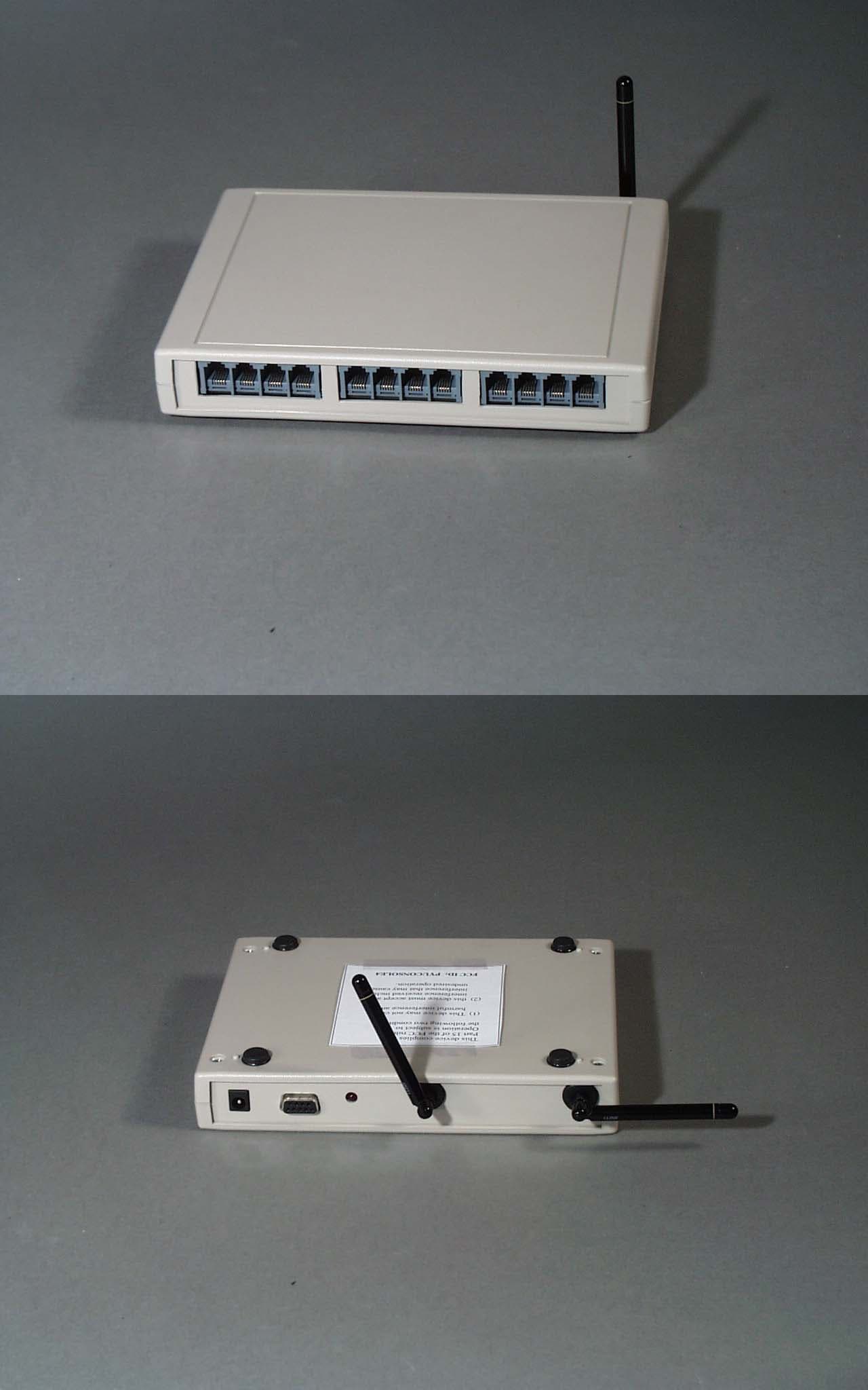
Click to zoom
Application Details
- Equipment Class
- DXT - Part 15 Low Power Transceiver, Rx Verified
- Date of Grant
- Nov 20, 2001
- Application Purpose
- Original Equipment
- Date of Application
- Nov 20, 2001
- Equipment Note
- Perception Analyzer Model 400 Console
- Frequency Range
- 905.00000000 - 920.00000000
- Company
- MSInteractive, L.L.C.
- Country
- United States
Documents & Files
Document Text
Text extracted from the exhibit documents filed with the FCC. Open a document above to read the original.
Users Manual
EXHIBIT K – User Manual FCC ID# PYUCONSOLE4 Perception Analyzer for Windows WIRELESS SYSTEM USER GUIDE MSInteractive version 6.31 10/24/2001 2 3 Contents 5 SECTION ONE: INTRODUCTION 5 I. What is the Perception Analyzer? 6 II. Getting Started With Your New Perception Analyzer System 11 SECTION TWO: PAEdit: The Question Editor 11 I. Getting Started 13 II. Writing the Questionnaire: General 14 III. Discrete-Choice Questions 16 IV. Intensity Scale Questions 17 V. Moment-to-Moment Questions 21 SECTION THREE: PACollect: Data Collection 21 I. Overview 21 II. Hardware Setup 24 III. Starting the Software: Session Dial-Configuration and Testing 30 IV. Optimizing Wireless Reception 32 V. Connecting the Dials by Wire 34 VI. Session Dial-Configuration Using Dial Status and Quick Configuration 36 VII. Other Pre-Session Preparations 41 VIII. Console and Dial Assignment 43 IX. Running a Session 43 -Selecting Questions and Reading the Dials 44 -Identifying and Solving Dial Problems in Session 46 -Exchanging Dials in Session 47 SECTION FOUR: PAReport: Data Reporting 47 I. Getting Started 48 II. Modifying Question Data Display 48 -Data Display Formats 48 -Aggregating Data 49 -Viewing Subsets 50 III. Printing 51 -Creating and Printing Cross-tabulated Tables 52 -Viewing and Printing Moment-to-Moment Graphs 4 5 Perception Analyzer for Windows USER GUIDE Section One: INTRODUCTION I. What is the Perception Analyzer? The Perception Analyzer is a computer system used to administer survey questions to a group of people. Data from multiple groups can then be aggregated, printed or exported to popular statistical-analysis software packages. It consists of hardware and software controlled by an ordinary Windows computer: • During a Perception Analyzer question session, participants use handheld dials to select a number corresponding with their answer to each question. • The dial transmits that number by radio to a receiver “console” connected to an ordinary Windows computer. The computer records the answers. • Two separate computer displays may be used: One to show questions to participants (“Participant Display”) and one to instantly show results to operators and observers in an easy to understand graphical form (“Results Display.”) • Questionnaire design, data collection, and data reporting are all controlled by the Windows Perception Analyzer software. 6 II. Getting Started With Your Analyzer System These are the steps you must complete to try out your new PA system: 1. Install the Analyzer software on a Windows computer. This will install the Launch icon on your computer’s desktop. Double clicking on Launch opens a screen that gives you the choice to start one of the four modules of the software. 2. Create and save a survey questionnaire (project) using the Edit software module. 3. Set up the dials and console interface for a data collection test by referring to the Hardware Setup Utility software module. Don’t worry yet if the system is unable to recognize all of the dials --that won’t be necessary to do a test and will be addressed in this manual in detail. 4. To collect answers using the dials, open Collect and select the project file you created with Edit. Use the Report software module to review graphs and tables of the collected responses. THE SOFTWARE: INSTALLATION AND OVERVIEW To install the software on a Windows computer: 1. Start the computer and insert disk 1 into the floppy disk drive. 2. From the Windows Start menu, select Run. The Run dialog window will open. In the entry field, type A:\SETUP.EXE and click OK. The setup program will guide you through the installation process. Accept the default settings offered. When prompted, enter the installation code provided with your software. The Setup Screen will appear: 3. This screen gives the option to enable the participant display to show questions to participants during data collection. This is either via the main monitor port of the computer, or via an optional hardware device (a PC-card, or network connection to another PC or handheld PC) that provides a second monitor-output from the computer. Before data collection, consult with your Perception Analyzer sales associate for configuration instructions for the method you have chosen. If you will not be using secondary (participant) display, select None. Also, it is important to set the Default Console in the lower right of the screen: click the button for the Wireless console option. 7 The installation will place the Launch icon on your computer’s desktop. To begin using the Analyzer software, double click on this icon. The following dialog will appear: The Analyzer software package consists of three main programs that take you through the process of executing a research project: Edit: the Question Editor. It’s used to write the master questionnaire for the study and enter information about the number of sessions of participants to be questioned. Collect: Data Collection. It controls the hardware in a survey session to display questions to participants, collect answers from the dials, and show graphical results to observers. Report: It’s used after the survey session(s) to aggregate, display and print the collected data. View graphical results, answer sheets, statistical frequencies, and cross- tabulations. The Analyzer also has two supporting utility: Hardware Setup: A self-guided tour of the proper setup of the Analyzer console, dials, and participant display. Peer to Peer Wizard: A guide to setting up and testing Peer to Peer networking to allow remote data review live during data collection. (Optional) 8 IDENTIFYING YOUR WIRELESS ANALYZER HARDWARE Your new Analyzer system consists of the following hardware components packed in the gray system case: • Dials and Console. The console is packed in the dial case beneath the foam dial tray: IMPORTANT: Be certain you are using the correct DC power supply (labeled “Console Power Supply”) for the console interface. Failure to use the correct power supply m…
Text truncated - open the document above for the full version.
Block Diagram
EXHIBIT F – Frequency Block Diagram FCC ID# PYUCONSOLE4 CONSOLE BLOCK DIAGRAM T/R SWITCH LPF LNA TRANSCEIVER IC VCO 905-925 MHZ IF 10.7 MHZ SYNTHESIZER CLOCK 16 MHZ CHANNEL 1 IN/OUT MICROPROCESSOR POWER SUPPLY 5V WALL BUG WIRED COM ANT 1 ANT 0 CHANNEL 0 IDENTICAL TO CHANNEL 1 RS 232 SERIAL PORT
Cover Letter(s)
EXHIBIT A – Agent Authorization FCC ID# PYUCONSOLE4
Cover Letter(s)
Exhibits for the FCC application of MSInteractive, L.L.C. Perception Analyzer Model 400 Console FCC ID: PYUCONSOLE4 Exhibit Description File Name Confidential Exhibit A Agent Authorization Agent Authorization.pdf Exhibit B Antenna Description Antenna Description.pdf Exhibit C Cover letter from Agent Cover letter from Agent.pdf Exhibit D External Photos External Photos.pdf Exhibit E FCC ID Label & Location FCC ID Label & Location.pdf Exhibit F Frequency Block Diagram Frequency Block Diagram.pdf Exhibit G Internal Photos Internal Photos.pdf Exhibit H Operational Description Operational Description.pdf Exhibit I Schematics Schematics.pdf Exhibit J Test Setup Photos Test Setup Photos.pdf Exhibit K User Manual User Manual.pdf Exhibit L Technical Report Technical Report.pdf Exhibit M AC Powerline Conducted Emissions AC Powerline Conducted Emissions.pdf Exhibit N Radiated Emissions Radiated Emissions.pdf
Cover Letter(s)
EXHIBIT C – Cover letter from Agent FCC ID# PYUCONSOLE4 NORTHWEST EMC, INC. 22975 NW Evergreen Parkway, Suite 400 Hillsboro, OR 97124 November 14, 2001 Dear Application Examiner: On behalf of MSInteractive, L.L.C., Northwest EMC, Inc is submitting this application for the certification of the Perception Analyzer Model 400 Console. The Console is part of a wireless perception analyzer system used in marketing research. A test subject uses a dial unit with a potentiometer to “dial” or register their reaction to a marketing presentation. The Console polls the dial units for data corresponding to each participant’s reaction. The Console is an unlicensed, low power transmitter that uses FM modulation at fixed frequency channels of 905, 908, 911, 914, 917 and 920 MHz. The EUT can be configured with only one antenna. Data is supplied with this application in support of this antenna. The technical report and exhibits demonstrate compliance with FCC rules 47 CFR 15.249. To facilitate the review process, an index of exhibits has been provided (see file “Index of exhibits.pdf”). Your efforts in reviewing this application are greatly appreciated. Best regards, Greg Kiemel, Director of Engineering Northwest EMC, Inc.
External Photos
EXHIBIT D – External Photos FCC ID# PYUCONSOLE4
ID Label/Location Info
EXHIBIT E – FCC ID Label & Location FCC ID# PYUCONSOLE4 Location of FCC ID Label
Internal Photos
EXHIBIT G – Internal Photos FCC ID# PYUCONSOLE4
Operational Description
EXHIBIT H – Operational Description FCC ID# PYUCONSOLE4 Console Description of Operation The console and dial are part of perception analyzer system used in marketing research. The console polls dials and receives back from the dials data corresponding to each participant reaction. Both console and dial are essentially FM data transceivers and they both employs identical superheterodine scheme receivers with 10.7 Mhz IF. The data rate is 4.8 kBps and the deviation is set to 60 khz pp. All the clock signals for the console are derived from single TCXO 16.000.00 Mhz with +/- 5ppm frequency stability. This defines tuning frequency accuracy The transmit path includes synthesized RF oscillator, buffer and power amplifier. All those components are incorporated into transceiver IC. To supress harmonics and reduce RF leak to antenna the low pass filter and transmit-receive switch are used. To improve reception in the office environment console has two channels – channel zero works with vertical polarization antenna and channel one works with horizontal one. Console uses quarter wave monopole antennas which are permanently attached to the PCB. There are 6 operating frequencies 905, 908, 911, 914, 917 and 920 Mhz. Console and dial are both operate at one frequency. All functions are controlled by microprocessor. The computer talks to the console and collects all the data received from the dials. Also the service and maintenance commands such as battery voltage check and receive signal strength are incorporated .
Operational Description
EXHIBIT B – Antenna Description FCC ID# PYUCONSOLE4 Console Antenna Description To improve reception in the office environment console has two channels – channel zero works with vertical polarization antenna and channel one works with horizontal one. Console uses quarter wave monopole antennas which are permanently mounted to the PCB and user does not have access to them. Antennas used are LINX # ANT-916-PW. The maximum gain is 3 dBi. ZONEREVDESCRIPTIONDATE APPROVED LINX TECHNOLOGIES 575 S.E. Ashley, Pl. Grants Pass, OR 97526 PHONE: 541-471-6256 FAX: 541-471-6251 www.linxtechnologies.com SIZE A FSCM NO.DWG NO. DESIGN: DRAWING: Chris APPROVED: SERIES NUMBER STATUS: DRAFT/APPROVED DATE: 12/15/97 PAT H PART NUMBER SHEET SCALE Covers Part #s 2.03" 0.30" Dia. 0.50" 6.94" - 418 MHz 6.75" - 433 MHz 2.92" - 916 MHz 0.175" 0.31" RG-174 Coax 8.5" 0.25" - 28 TPI 315 MHz = ANT-315-PW-QW 418 MHz = ANT-418-PW-QW 433 MHz = ANT-433-PW-QW Threads common to ground PERMANENT STUD-MOUNT 1/4-WAVE WHIP ANTENNAS CH1 S 11 SWR1 / REF 1 SPAN = 200 MHz 1 MARKER 1 hp 1: 1.0363 Marker 1 = Specified Center Frequency SPAN = 200 MHz Marker 1 = Specified Center Frequency 1 CH1 MEM 1: 49.658 Ω1.4551 Ω 552.7pH
Schematics
EXHIBIT I – Schematics FCC ID# PYUCONSOLE4 11 A A ANT0 ANT 1 C_RFIN J G:\COL3\CONSOLE\REVJ\SCH\CONSOLE.DSN B 1 8 Thursday, October 04, 2001 TitleSize Document Number Rev Date: Sheet of RXRF0TXRF0 RXEN0TXEN0 RXRF1TXRF1 RXEN1TXEN1 U510UPG152TA 23 456 1 GND OUT2 VC2INVC1 OUT1 U532SAW 915 2 1 3 4 6 5 IN GND GND GND GND OUT C5304pF 12 C5204pF 12 L521 4.7nH C511100pF 1 2 R512330 12 U522 RF2323 4 3 5 1 2 U501SAW 915 2 1 3 4 6 5 IN GND GND GND GND OUT C531100pF 1 2 C50222pF 12 C50322pF 12 C523.01uF 12 U310UPG152TA 23 456 1 GND OUT2 VC2INVC1 OUT1 U332SAW 915 2 1 3 4 6 5 IN GND GND GND GND OUT C3304pF 12 C3214pF 12 L322 4.7nH C311100pF 1 2 R312330 12 U323 RF2323 4 3 5 1 2 U304SAW 915 2 1 3 4 6 5 IN GND GND GND GND OUT C331100pF 1 2 C30622pF 12 C30522pF 12 C324.01uF 12 A500ANT-916-PW-RA 1 A301ANT-916-PW-RA 1 11 A A !!! TEST WITH 0 OHM !!! TEST WITH 0 OHM/NR!! C_SYNTH J G:\COL3\CONSOLE\REVJ\SCH\CONSOLE.DSN B 2 8 Wednesday, October 10, 2001 TitleSize Document Number Rev Date: Sheet of C_SYNLEC_DATA C_LPF 16MHZ C_SYNCEC_CLK BUFF LODRIVE P5RF0 P5RF1 P5RF0 R423 10K 1 2 C460.047uF 12 C455 22pF 1 2 C442.01uF C4520.47uF C456 100pF 1 2 R451 NR 1 2 R431NR 12 R42510 12 R421 10K 1 2 R420 10K 1 2 C440.1UF R620 10K 1 2 C453NR 12 R422 10K 1 2 R424330 12 U441LMX2316 TM 8 16 15 346 131211 7 2149 5 10 1 OSCIN VP VCC2GNDGNDFINLEDATACLKVCC1 D0 F/LD GND FINCE FL C454.01uF 12 R485330 12 U483 RF2323 4 3 5 1 2 C484.01uF 12 R480100 1 2 C48222pF 1 2 R481 47 12 C47222pF 1 2 L4614.7nH C430.1UF U473 RF2323 4 3 5 1 2 R471330 1 2 R450 3.9K 12 R475330 12 R470 47 12 C462 22pF 12 C474.01uF 12 R476 NR 12 11 A A 230KHZ 230KHZ C_TRANSC0 J G:\COL3\CONSOLE\REVJ\SCH\CONSOLE.DSN B 3 8 Tuesday, October 16, 2001 TitleSize Document Number Rev Date: Sheet of TXRF0RXRF0TXEN0RXEN0 C_TXDATA\ BUFF RXDATA0RSSI0 C_LPF TXON0 P5VC P5RF0 P5RF0 P5RF0 P5RF0 P5RF0 P5RF0 L534 12nH L5714.7nH L5724.7nH D564 SMV1233-011 2 1 + C593 1000UF 6.3V L5386.8uH R52610 12 R55010 12 R580100 12 R56310K 12 R54168K 1 2 R540 47K 12 C591.01uF 12 C54210pF 12 C5703.3pF 1 2 C554.1uF 12 C545 10pF 12 C56122pF 12 C527.01uF 12 R54310K 12 R52510 12 Y586 CDA10.7MG20-A 12 R56010 12 C55322pF 12 R585 1K 12 R535NR 1 2 C533NR 12 C582.01uF 12 C588.01uF 12 C574 .01uF 12 R576 47K 12 C573 .01uF 12 U555RF2945 30 46798 1013111415171618 281224252629 2019 222127 231 3231 235 VCC3 RFIRFOGNDGNDMXIMXOIFIBP1BP2BP3IF2IIF1OBP5 VCC1 RSSI VCOP VCON VCOBUF DOUT GNDBP6 DCAP DEMI GND TXOGNDTXERXELVLAD MODIN GND C53722pF 12 C56222pF 1 2 C596.1uF 1 2 R59410K 12 R5976.8K 1 2 R566 0 1 2 R568 0 1 2 L592470uH R5771K 1 2 R640100K 1 2 C5834700pF 12 C595470pF 12 C524.01uF 12 C53622pF 12 C544 .01uF 12 C58122pF 12 FL567 SK107M2N-A0-00 1 3 2 C557 .01uF 12 C575 470pF 12 C552.1uF 12 FL556SK107M2N-A0-00 1 3 2 C565 .01uF 12 + C590 47uF 6.3V L587NR C584 NR 12 C551100pF 12 R745 100K 12 R744100K 12 ST303PCB STIF12345678 11 A A 230KHZ 230KHZ C_TRANSC1 J G:\COL3\CONSOLE\REVJ\SCH\CONSOLE.DSN B 4 8 Tuesday, October 16, 2001 TitleSize Document Number Rev Date: Sheet of TXRF1RXRF1TXEN1RXEN1 RXDATA1RSSI1 LODRIVE TXON1 P5VC P5RF1 P5RF1 P5RF1 P5RF1 P5RF1 P5RF1 L334 12nH L3724.7nH L3734.7nH + C393 1000UF 6.3V L3386.8uH R32710 12 R35010 12 R380100 12 R34068K 1 2 R341 47K 12 C391.01uF 12 C34210pF 12 C361.1uF 12 C345 10pF 12 C36222pF 12 C328.01uF 12 R34310K 12 R32610 12 Y386 CDA10.7MG20-A 12 R36010 12 C35322pF 12 R3851K 12 R335NR 1 2 C333NR 12 C382.01uF 12 C388.01uF 12 C375 .01uF 12 R377 47K 12 C374 .01uF 12 U354RF2945 30 46798 1013111415171618 281224252629 2019 222127 231 3231 235 VCC3 RFIRFOGNDGNDMXIMXOIFIBP1BP2BP3IF2IIF1OBP5 VCC1 RSSI VCOP VCON VCOBUF DOUT GNDBP6 DCAP DEMI GND TXOGNDTXERXELVLAD MODIN GND C33722pF 12 R365 0 1 2 R363 0 1 2 L392470uH R3781K 1 2 R641100K 1 2 C3834700pF 12 C325.01uF 12 C33622pF 12 R344 .01uF 12 C38122pF 12 FL366 SK107M2N-A0-00 1 3 2 C356 .01uF 12 C376 470pF 12 C351.1uF 12 FL355SK107M2N-A0-00 1 3 2 C364 .01uF 12 + C390 47uF 6.3V C3702pF 1 2 L387NR C384NR 12 C352100pF 12 R747 100K 12 R746100K 12 SH320NR123456789101112 C395NR 12 C3942pF 12 R371330 1 2 11 A A PDV1 RUN/IDLE\ RUN/IDLE\ NC PDV0 TESTCON C_UP0/HSPICS J G:\COL3\CONSOLE\REVJ\SCH\CONSOLE.DSN B 5 8 Thursday, October 04, 2001 TitleSize Document Number Rev Date: Sheet of PD0PD1PD2PD3PD4PD5PD6PD7PD0PD1PD5PD4PD3PD7PD2PD6 GND RXDATA1 RESET\ RXDATA016MHZ54 PDV0 PDV1 RUN/IDLE\ PD[0..7] RX_WIREC_TXDATAWIRESIGPICSEL0\PICSEL1\ C_TXDATA\ P5VC VCC P5VC P5VCP5VC P5VC P5VC P5VC P5VC P5VC P5VC P5VC U733M74HC541M 234567891 19 18171615141312112010 A1A2A3A4A5A6A7A8G1G2 Y1Y2Y3Y4Y5Y6Y7Y8 VCC GND U721PIC16C54-HS/SO 1615 14171812678910111213 534 OSC1OSC2 VDD RA0RA1RA2RA3 RB0RB1RB2RB3RB4RB5RB6RB7 VSSRTCCMCLRU723PIC16C54-HS/SO 1615 14171812678910111213 534 OSC1OSC2 VDD RA0RA1RA2RA3 RB0RB1RB2RB3RB4RB5RB6RB7 VSSRTCCMCLR C722.1uF 12 C642.1uF 12 C740.1uF 12 C622.1uF 12 U741AMM74HCT00M 12 3 U731M74HC541M 234567891 19 18171615141312112010 A1A2A3A4A5A6A7A8G1G2 Y1Y2Y3Y4Y5Y6Y7Y8 VCC GND U800NR 1 2 3 4 5 6 7 8 U801NR1 2 3 4 5 6 7 8 U753NR 1 2 3 4 5 6 7 8 9 10 11 12 13 14 15 16 R803NR R804NR R805NR R802NR U643 MM74HC4053M 1213 21536 1110 9 141541687 X0X1Y0Y1Z0Z1INHABC X Y Z VDD VSSVEE R74110K U741B MM74HCT00M 45 6 U741CMM74HCT00M 9 10 8 U741DMM74HCT00M 1213 11 J744 NR1234567 11 A A RA3 - SPARE ADC C_UP1/UP J G:\COL3\CONSOLE\REVJ\SCH\CONSOLE.DSN B 6 8 Thursday, October 04, 2001 TitleSize Document Number Rev Date: Sheet of RX232 PD0PD1PD2PD3PD4PD5PD6PD7 PD[0..7] TX23 2 PD0PD1PD2PD3PD4PD5PD6PD7 16MHZRESET\WIRESIG RSSI0RSSI1 RUN/IDLE\PICSEL0\PICSEL1\C_TXDATA TXEN0RXEN0TXEN1RXEN1 C_SYNCEC_SYNLEC_DATAC_CLK TXON0TXON1 PD[0..7] PDV0PDV1 16MHZ54 RX_WIRE P5VC P5VC P5VC P5VC P5VC P5VC P5VC P5VC P5VC P5VC P5VC P5VC P5VC P5VC U634 PIC16C74B-20/L 2 1415 345678 3637383941424344 1312 1618192025262729212223243031323391011 3534 1 172840 MCLR/VPPOSC1OSC2RA0RA1RA2RA3RA4/TOCK1RA5/SS RB0/INT RB1RB2RB3RB4RB5RB6RB7 VSSVDD RC0RC1 RC2/CCP1 RC3/SCK/SCL RC4/SDI/SDA RC5/SDO RC6RC7RD0RD1RD2RD3RD4RD5RD6RD7 RE0/RD RE1/WR RE2/CS VDDVSSNCNCNCNC J605 DB9 FEMALE 594837261 U623CMM74HCT00M 9 10 8 U623BMM74HCT00M 45 6 U633 M…
Text truncated - open the document above for the full version.
Test Report
EXHIBIT L – Technical Report FCC ID# PYUCONSOLE4 Measurement/Technical Report MSInteractive, L.L.C. Perception Analyzer Model 400 Console FCC ID: PYUCONSOLE4 October 02, 2001 This report concerns (check one): Original Grant X Class II Change____ Equipment Type: Unlicensed Low Power Transmitter Rule Part: 47 CFR 15.249 Deferred grant requested per 47 CFR 0.457 (d)(1)(ii)? Yes_____ no__X__ If yes, defer until: ______N/A______ date MSInteractive, L.L.C. agrees to notify the Commission by: ______N/A______ date of the intended date of announcement of the product so that the grant can be issued on that date. Transition Rules Request per 15.37: yes_____ no__X__ If no, assumed Part 15, Subpart C for intentional radiators – new 47 CFR [10-1-92] provision. Report prepared by: Northwest EMC, Inc. 22975 NW Evergreen Pkwy., Ste 400 Hillsboro, OR 97124 (503) 844-4066 fax: (503) 844-3826 Report No. SEIT0050 FCC ID: PYUCONSOLE4 Northwest EMC, Inc. Report No. SEIT0050 Page 2 Table of Contents Section Description Page 1.0 General Information 3 1.1 Product Description 3 1.2 Related Submittals/Grants 4 1.3 Tested System Details 4 1.4 Test Methodology 5 1.5 Test Facility 5 2.0 System Test Configuration 6 2.1 Justification 6 2.2 EUT Exercise Software 6 2.3 Special Accessories 6 2.4 Equipment Modifications 6 Figure 2.1 Configuration of Tested System 7 3.0 Antenna Requirement 8 3.1 Antenna Information 8 3.2 RF Exposure Compliance Requirements 8 4.0 AC Powerline Conducted Emissions 9 4.1 Harmonics and Spurious Radiated Emissions 10 4.2 Fundamental Emissions 11 5.0 Field Strength Calculations 12 5.1 Measurement Bandwidths 12 6.0 Measurement Equipment 13 FCC ID: PYUCONSOLE4 Northwest EMC, Inc. Report No. SEIT0050 Page 3 1.0 General Information 1.1 Product Description Manufactured By .............................................................................................. MSInteractive, L.L.C. Address ................................................111 SW 5 TH Avenue, Suite 1850, Portland, OR 97204 USA Test Requested By:.................................................................... Forrest Seitz of Seitz & Associates Model................................................................................. Perception Analyzer Model 400 Console FCC ID.................................................................................................................... PYUCONSOLE4 Serial Number(s) ........................................................................................................................ none Date of Test............................................................. September 25, 2001 through October 02, 2001 Job Number........................................................................................................................ SEIT0050 Prepared By: Vicki Albertson, Technical Report and Documentation Manager Technical Review By: Approved By: Greg Kiemel, Director of Engineering Don Facteau, IS Manager FCC ID: PYUCONSOLE4 Northwest EMC, Inc. Report No. SEIT0050 Page 4 1.1 Product Description con’t The Equipment Under Test (EUT) is the MSInteractive, L.L.C. Perception Analyzer Model 400 Console module. The Console is part of a wireless perception analyzer system used in marketing research. A test subject uses a dial unit with a potentiometer to “dial” or register their reaction to a marketing presentation. The Console polls the dial units for data corresponding to each participant’s reaction. The Console is an unlicensed, low power transmitter that uses FM modulation at fixed frequency channels of 905, 908, 911, 914, 917 and 920 MHz. The EUT can be configured with only one antenna. Data is supplied with this application in support of this antenna. The technical report and exhibits demonstrate compliance with FCC rules 47 CFR 15.249. 1.2 Related Submittals/Grants None 1.3 Tested System Details EUT and Peripherals Item FCC ID Description and Serial No. EUT PYUCONSOLE4 MSInteractive, L.L.C. Perception Analyzer Model 400 Console S/N none. AC Adapter for EUT N/A Cui Stack, Model DV-530R, S/N DPRO50030-P6 Cables Cable Type Shield Length (meters) Ferrite Connection Point 1 Connection Point 2 Dial No 1.5 No RJ11 on EUT Unterminated DC No 2.0 No AC Adapter for EUT DC input of EUT RS232 Yes 1.2 No RS232 on EUT Unterminated FCC ID: PYUCONSOLE4 Northwest EMC, Inc. Report No. SEIT0050 Page 5 1.4 Test Methodology Radiated testing was performed according to the procedures in ANSI C63.4 (1992. Radiated testing was performed at an antenna to EUT distance of 3 meters, from 30 MHz to 10 GHz. 1.5 Test Facility The semi-anechoic chamber and conducted measurement facility used to collect the radiated and conducted data is located at Northwest EMC, Inc. 22975 NW Evergreen Pkwy., Ste 400 Hillsboro, OR 97124 (503) 844-4066 Fax: 844-3826 The semi-anechoic chamber, and conducted measurement facility is located in Hillsboro, OR, at the address shown above. This site has been fully described in a report filed with the FCC (Federal Communications Commission), and accepted by the FCC in a letter maintained in our files. Northwest EMC, Inc. is recognized under the United States Department of Commerce, National Institute of Standards and Technology, National Voluntary Laboratory Accreditation Program (NVLAP) for satisfactory compliance with criteria established in Title 15, Part 285 Code of Federal Regulations. These criteria encompass the requirements of ISO/IEC Guide 25 and the relevant requirements of ISO 9002 (ANSI/ASQC Q92-1987) as suppliers of calibration or test results. NVLAP Lab Code: 200059-0. FCC ID: PYUCONSOLE4 Northwest EMC, Inc. Report No. SEIT0050 Page 6 2.0 System Test Configuration 2.1 Justification 2.1.1 Operating Modes All operating modes of the EUT were investigated. The EUT was configured to continuously transmit and receive. Both radiated and conducted measurements were made with the radio transmitting at the lowest channel, a middle channel, and the highest channel available. 2.1.2 Test …
Text truncated - open the document above for the full version.
Test Report
EXHIBIT M – AC Powerline Conducted Emissions FCC ID# PYUCONSOLE4 NORTHWEST EMC Rev 4.10 07/06/01 EUT: Perception Analyzer Model 400 ConsoleWork Order: SEIT0050 Serial Number: noneDate: 10/02/01 Customer:Seitz & AssociatesTemperature:22 Attendees :N/ATester: Greg KiemelHumidity:42% Customer Ref. No.:N/APower: 120 V, 60 HzJob Site: EV01 TEST SPECIFICATIONS Specification: FCC Class BYear:2000Method:ANSI C63.4Year: 1992 SAMPLE CALCULATION S Radiated Emissions:Field Strength = Measured Level + Antenna Factor + Cable Attenuation Factor - Amplifier Gain Conducted Emissions:Adjusted Level = Measured Level + Transducer Factor + Cable Attenuation Factor + External Attenuator COMMENTS EUT OPERATING MODES DEVIATIONS FROM TEST STANDAR D RESULTSDISTANCE (m)LINERUN PASSHigh LineRun #01 OTHER Tested By FrequencyDetector Adjusted LevelMargin (MHz)(dBuV)(dB) 0.476Peak43.6-4.4 0.495Peak43.6-4.4 0.508Peak43.3-4.7 0.498Peak43.2-4.8 0.486Peak43.1-4.9 0.520Peak42.9-5.1 0.538Peak42.4-5.6 0.551Peak42.3-5.7 0.586Peak41.1-6.9 0.564Peak41.0-7.0 0.649Peak39.8-8.2 0.521Peak39.6-8.4 0.646Peak39.4-8.6 0.658Peak39.2-8.8 0.628Peak39.0-9.0 0.637Peak38.7-9.3 0.671Peak38.1-9.9 0.689Peak37.8-10.2 0.591Peak37.7-10.3 0.574Peak37.7-10.3 Radiated and Conducted Emissions 120 V, 60 Hz mains. Xmitter set to Low Channel. See Comments None 17.720.048.0 17.720.048.0 18.120.048.0 17.820.048.0 19.020.048.0 18.720.048.0 19.420.048.0 19.220.048.0 19.820.048.0 19.620.048.0 21.120.048.0 21.020.048.0 22.420.048.0 22.320.048.0 23.120.048.0 22.920.048.0 23.320.048.0 23.220.048.0 23.620.048.0 23.620.048.0 Meter ReadingCorrection FactorSpecification Limit (dBuV)(dB)(dBuV) 10.0 15.0 20.0 25.0 30.0 35.0 40.0 45.0 50.0 0.1001.00010.000100.000 Frequency (MHz) dBuV NORTHWEST EMC Rev 4.10 07/06/01 EUT: Perception Analyzer Model 400 ConsoleWork Order: SEIT0050 Serial Number: noneDate: 10/02/01 Customer: Seitz & AssociatesTemperature: 22 Attendees: N/ATester: Greg KiemelHumidity: 42% Customer Ref. No.: N/APower: 120 V, 60 HzJob Site: EV01 TEST SPECIFICATIONS Specification: FCC Class BYear:2000Method: ANSI C63.4Year: 1992 SAMPLE CALCULATIONS Radiated Emissions:Field Strength = Measured Level + Antenna Factor + Cable Attenuation Factor - Amplifier Gain Conducted Emissions:Adjusted Level = Measured Level + Transducer Factor + Cable Attenuation Factor + External Attenuator COMMENTS EUT OPERATING MODES DEVIATIONS FROM TEST STANDARD RESULTSDISTANCE (m)LINERUN PASSLow LineRun #02 OTHER Tested By FrequencyDetector Adjusted LevelMargin (MHz)(dBuV)(dB) 0.460Peak40.4-7.6 0.495Peak38.3-9.7 0.467Peak37.8-10.2 0.469Peak37.8-10.2 0.507Peak37.7-10.3 0.482Peak37.6-10.4 0.497Peak35.5-12.5 0.489Peak35.0-13.0 6.127Peak34.0-14.0 0.592Peak33.5-14.5 0.593Peak33.5-14.5 0.621Peak33.3-14.7 0.658Peak32.6-15.4 5.855Peak32.5-15.5 4.851Peak32.3-15.7 6.362Peak32.2-15.8 0.634Peak32.1-15.9 0.600Peak32.1-15.9 6.380Peak32.1-15.9 0.611Peak32.0-16.0 Radiated and Conducted Emissions 120 V, 60 Hz mains. Xmitter set to Low Channel. See Comments None 11.220.948.0 12.020.048.0 12.120.048.0 12.120.048.0 11.420.948.0 11.320.948.0 12.620.048.0 11.620.948.0 13.520.048.0 13.320.048.0 13.120.948.0 13.520.048.0 15.520.048.0 15.020.048.0 17.720.048.0 17.620.048.0 17.820.048.0 17.820.048.0 20.420.048.0 18.320.048.0 Meter ReadingCorrection FactorSpecification Limit (dBuV)(dB)(dBuV) 10.0 15.0 20.0 25.0 30.0 35.0 40.0 45.0 50.0 0.1001.00010.000100.000 Frequency (MHz) dBuV NORTHWEST EMC Rev 4.10 07/06/01 EUT: Perception Analyzer Model 400 ConsoleWork Order: SEIT0050 Serial Number: noneDate: 10/02/01 Customer: Seitz & AssociatesTemperature: 22 Attendees: N/ATester: Greg KiemelHumidity: 42% Customer Ref. No.: N/APower: 120 V, 60 HzJob Site: EV01 TEST SPECIFICATIONS Specification: FCC Class BYear:2000Method: ANSI C63.4Year: 1992 SAMPLE CALCULATIONS Radiated Emissions:Field Strength = Measured Level + Antenna Factor + Cable Attenuation Factor - Amplifier Gain Conducted Emissions:Adjusted Level = Measured Level + Transducer Factor + Cable Attenuation Factor + External Attenuator COMMENTS EUT OPERATING MODES DEVIATIONS FROM TEST STANDARD RESULTSDISTANCE (m)LINERUN PASSHigh LineRun #03 OTHER Tested By FrequencyDetector Adjusted LevelMargin (MHz)(dBuV)(dB) 0.450Peak45.0-3.0 0.463Peak44.1-3.9 0.471Peak43.5-4.5 0.515Peak43.3-4.7 0.487Peak42.6-5.4 0.480Peak42.5-5.5 0.542Peak42.5-5.5 0.534Peak42.4-5.6 0.564Peak41.7-6.3 0.614Peak41.1-6.9 0.601Peak40.8-7.2 0.601Peak40.8-7.2 0.501Peak40.5-7.5 0.622Peak40.4-7.6 0.630Peak39.6-8.4 0.667Peak39.5-8.5 0.522Peak39.0-9.0 0.639Peak39.0-9.0 0.685Peak37.8-10.2 0.580Peak37.8-10.2 Radiated and Conducted Emissions 120 V, 60 Hz mains. Xmitter set to Mid Channel. See Comments None 17.820.048.0 17.820.048.0 19.020.048.0 19.020.048.0 19.620.048.0 19.520.048.0 20.520.048.0 20.420.048.0 20.820.048.0 20.820.048.0 21.720.048.0 21.120.048.0 22.520.048.0 22.420.048.0 22.620.048.0 22.520.048.0 23.520.048.0 23.320.048.0 25.020.048.0 24.120.048.0 Meter ReadingCorrection FactorSpecification Limit (dBuV)(dB)(dBuV) 10.0 15.0 20.0 25.0 30.0 35.0 40.0 45.0 50.0 0.1001.00010.000100.000 Frequency (MHz) dBuV NORTHWEST EMC Rev 4.10 07/06/01 EUT: Perception Analyzer Model 400 ConsoleWork Order: SEIT0050 Serial Number: noneDate: 10/02/01 Customer: Seitz & AssociatesTemperature: 22 Attendees: N/ATester: Greg KiemelHumidity: 42% Customer Ref. No.: N/APower: 120 V, 60 HzJob Site: EV01 TEST SPECIFICATIONS Specification: FCC Class BYear:2000Method: ANSI C63.4Year: 1992 SAMPLE CALCULATIONS Radiated Emissions:Field Strength = Measured Level + Antenna Factor + Cable Attenuation Factor - Amplifier Gain Conducted Emissions:Adjusted Level = Measured Level + Transducer Factor + Cable Attenuation Factor + External Attenuator COMMENTS EUT OPERATING MODES DEVIATIONS FROM TEST STANDARD RESULTSDISTANCE (m)LINERUN PASSLow LineRun #04 OTHER Tested By FrequencyDetector Adjusted LevelMargin (MHz)(dBuV)(dB) 0.458Peak38.8-9.2 0.488Peak38.0-10.0 0.506Peak37.8-10.2 0.476Peak37.8-10.2 0.471Peak37.8-10.2 0.482Peak37.1-10.9 0.500Peak37.…
Text truncated - open the document above for the full version.
Test Report
EXHIBIT N – Radiated Emissions FCC ID# PYUCONSOLE4 NORTHWEST EMC Rev 4.10 07/06/01 EUT: Perception Analyzer Model 400 ConsoleWork Order: SEIT0050 Serial Number: noneDate: 9/25/2001 & 10/02/2001 Customer: Seitz & AssociatesTemperature: 22 Attendees: N/ATester: Rod PeloquinHumidity: 42% Customer Ref. No.: N/APower: 120 V, 60 HzJob Site: EV01 TEST SPECIFICATIONS Specification: FCC 15.249Year:2000Method: ANSI C63.4Year: 1992 SAMPLE CALCULATIONS Radiated Emissions:Field Strength = Measured Level + Antenna Factor + Cable Attenuation Factor - Amplifier Gain Conducted Emissions:Adjusted Level = Measured Level + Transducer Fact…
Text truncated - open the document above for the full version.
Contact Information
Applicant
Daniel R Welch(Product Analyst)
Technical Contact
Northwest EMC, Inc.Greg V Kiemel
[email protected]503-844-4066
22975 NW Evergreen Parkway · Hillsboro, Oregon · United States
Non-Technical Contact
Northwest EMC, Inc.Vicki L Albertson
[email protected]503-844-4066
Test Firm
Northwest EMC, Inc.Greg Kiemel
Technical Specifications
| # | Rule Parts | Frequency Range | Power Output |
|---|---|---|---|
| 1 | 15C | 905 MHz - 920 MHz | - |
Other Applications from MSInteractive, L.L.C.
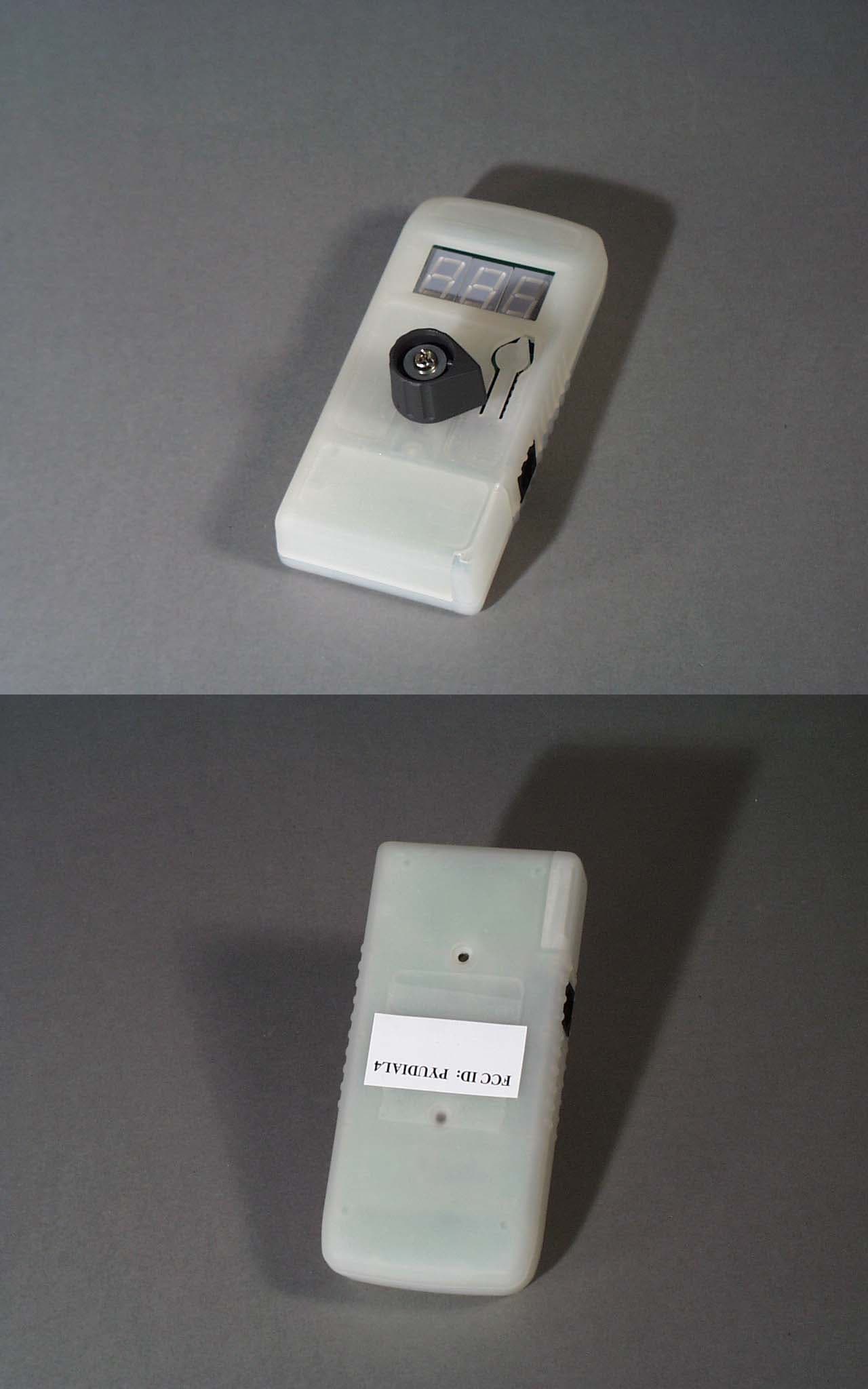
PYUDIAL4
Dec 10, 2001Perception Analyzer Model 400 Handset
Equipment Class
DXX - Part 15 Low Power Communication Device Transmitter