PYUDIAL4Perception Analyzer Model 400 Handset
MSInteractive, L.L.C.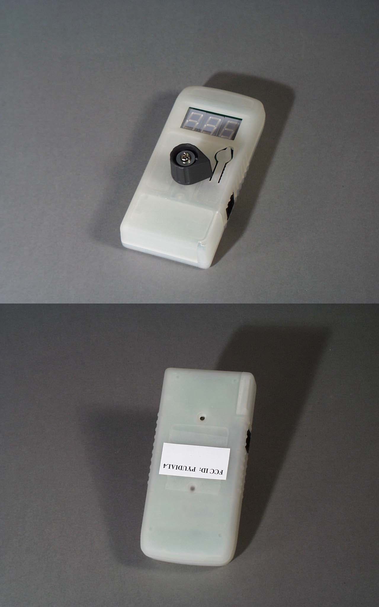
Click to zoom
Application Details
- Equipment Class
- DXX - Part 15 Low Power Communication Device Transmitter
- Date of Grant
- Dec 10, 2001
- Application Purpose
- Original Equipment
- Date of Application
- Dec 10, 2001
- Equipment Note
- Perception Analyzer Model 400 Handset
- Frequency Range
- 905.00000000 - 920.00000000
- Company
- MSInteractive, L.L.C.
- Country
- United States
Documents & Files
Document Text
Text extracted from the exhibit documents filed with the FCC. Open a document above to read the original.
Users Manual
EXHIBIT K – User Manual FCC ID# PYUDIAL4 Perception Analyzer for Windows WIRELESS SYSTEM USER GUIDE MSInteractive version 6.31 10/24/2001 2 3 Contents 5 SECTION ONE: INTRODUCTION 5 I. What is the Perception Analyzer? 6 II. Getting Started With Your New Perception Analyzer System 11 SECTION TWO: PAEdit: The Question Editor 11 I. Getting Started 13 II. Writing the Questionnaire: General 14 III. Discrete-Choice Questions 16 IV. Intensity Scale Questions 17 V. Moment-to-Moment Questions 21 SECTION THREE: PACollect: Data Collection 21 I. Overview 21 II. Hardware Setup 24 III. Starting the Software: Session Dial-Configuration and Testing 30 IV. Optimizing Wireless Reception 32 V. Connecting the Dials by Wire 34 VI. Session Dial-Configuration Using Dial Status and Quick Configuration 36 VII. Other Pre-Session Preparations 41 VIII. Console and Dial Assignment 43 IX. Running a Session 43 -Selecting Questions and Reading the Dials 44 -Identifying and Solving Dial Problems in Session 46 -Exchanging Dials in Session 47 SECTION FOUR: PAReport: Data Reporting 47 I. Getting Started 48 II. Modifying Question Data Display 48 -Data Display Formats 48 -Aggregating Data 49 -Viewing Subsets 50 III. Printing 51 -Creating and Printing Cross-tabulated Tables 52 -Viewing and Printing Moment-to-Moment Graphs 4 5 Perception Analyzer for Windows USER GUIDE Section One: INTRODUCTION I. What is the Perception Analyzer? The Perception Analyzer is a computer system used to administer survey questions to a group of people. Data from multiple groups can then be aggregated, printed or exported to popular statistical-analysis software packages. It consists of hardware and software controlled by an ordinary Windows computer: • During a Perception Analyzer question session, participants use handheld dials to select a number corresponding with their answer to each question. • The dial transmits that number by radio to a receiver “console” connected to an ordinary Windows computer. The computer records the answers. • Two separate computer displays may be used: One to show questions to participants (“Participant Display”) and one to instantly show results to operators and observers in an easy to understand graphical form (“Results Display.”) • Questionnaire design, data collection, and data reporting are all controlled by the Windows Perception Analyzer software. 6 II. Getting Started With Your Analyzer System These are the steps you must complete to try out your new PA system: 1. Install the Analyzer software on a Windows computer. This will install the Launch icon on your computer’s desktop. Double clicking on Launch opens a screen that gives you the choice to start one of the four modules of the software. 2. Create and save a survey questionnaire (project) using the Edit software module. 3. Set up the dials and console interface for a data collection test by referring to the Hardware Setup Utility software module. Don’t worry yet if the system is unable to recognize all of the dials --that won’t be necessary to do a test and will be addressed in this manual in detail. 4. To collect answers using the dials, open Collect and select the project file you created with Edit. Use the Report software module to review graphs and tables of the collected responses. THE SOFTWARE: INSTALLATION AND OVERVIEW To install the software on a Windows computer: 1. Start the computer and insert disk 1 into the floppy disk drive. 2. From the Windows Start menu, select Run. The Run dialog window will open. In the entry field, type A:\SETUP.EXE and click OK. The setup program will guide you through the installation process. Accept the default settings offered. When prompted, enter the installation code provided with your software. The Setup Screen will appear: 3. This screen gives the option to enable the participant display to show questions to participants during data collection. This is either via the main monitor port of the computer, or via an optional hardware device (a PC-card, or network connection to another PC or handheld PC) that provides a second monitor-output from the computer. Before data collection, consult with your Perception Analyzer sales associate for configuration instructions for the method you have chosen. If you will not be using secondary (participant) display, select None. Also, it is important to set the Default Console in the lower right of the screen: click the button for the Wireless console option. 7 The installation will place the Launch icon on your computer’s desktop. To begin using the Analyzer software, double click on this icon. The following dialog will appear: The Analyzer software package consists of three main programs that take you through the process of executing a research project: Edit: the Question Editor. It’s used to write the master questionnaire for the study and enter information about the number of sessions of participants to be questioned. Collect: Data Collection. It controls the hardware in a survey session to display questions to participants, collect answers from the dials, and show graphical results to observers. Report: It’s used after the survey session(s) to aggregate, display and print the collected data. View graphical results, answer sheets, statistical frequencies, and cross- tabulations. The Analyzer also has two supporting utility: Hardware Setup: A self-guided tour of the proper setup of the Analyzer console, dials, and participant display. Peer to Peer Wizard: A guide to setting up and testing Peer to Peer networking to allow remote data review live during data collection. (Optional) 8 IDENTIFYING YOUR WIRELESS ANALYZER HARDWARE Your new Analyzer system consists of the following hardware components packed in the gray system case: • Dials and Console. The console is packed in the dial case beneath the foam dial tray: IMPORTANT: Be certain you are using the correct DC power supply (labeled “Console Power Supply”) for the console interface. Failure to use the correct power supply may …
Text truncated - open the document above for the full version.
Block Diagram
EXHIBIT F – Frequency Block Diagram FCC ID# PYUDIAL4 DIAL BLOCK DIAGRAM T/R SWITCH LPF LNA TRANSCEIVER IC VCO 905-925 MHZ IF 10.7 MHZ SYNTHESIZER CLOCK 4 MHZ MICROPROCESSOR DIAL POT LED DISPLAY POWER SUPPLY 9V BATTERY WIRED COM PORT PCB ANTENNA
Cover Letter(s)
EXHIBIT A – Agent Authorization FCC ID# PYUDIAL4
Cover Letter(s)
EXHIBIT C – Cover Letter from Agent FCC ID# PYUDIAL4 NORTHWEST EMC, INC. 22975 NW Evergreen Parkway, Suite 400 Hillsboro, OR 97124 November 14, 2001 Dear Application Examiner: On behalf of MSInteractive, L.L.C., Northwest EMC, Inc is submitting this application for the certification of the Perception Analyzer Model 400 Handset. The Handset is part of a wireless perception analyzer system used in marketing research. A test subject uses a handset unit with a potentiometer to “dial” or register their reaction to a marketing presentation. The Console polls the handset units for data corresponding to each participant’s reaction. The Perception Analyzer Model 400 Handset is an unlicensed, low power transmitter that uses FM modulation at fixed frequency channels of 905, 908, 911, 914, 917 and 920 MHz. The EUT can be configured with only one antenna. Data is supplied with this application in support of this antenna. The technical report and exhibits demonstrate compliance with FCC rules 47 CFR 15.249. To facilitate the review process, an index of exhibits has been provided (see file “Index of exhibits.pdf”). Your efforts in reviewing this application are greatly appreciated. Best regards, Greg Kiemel, Director of Engineering Northwest EMC, Inc.
Cover Letter(s)
Exhibits for the FCC application of MSInteractive, L.L.C. Perception Analyzer Model 400 Handset FCC ID: PYUDIAL4 Exhibit Description File Name Confidential Exhibit A Agent Authorization Agent Authorization.pdf Exhibit B Antenna Description Antenna Description.pdf Exhibit C Cover letter from Agent Cover letter from Agent.pdf Exhibit D External Photos External Photos.pdf Exhibit E FCC ID Label & Location FCC ID Label & Location.pdf Exhibit F Frequency Block Diagram Frequency Block Diagram.pdf Exhibit G Internal Photos Internal Photos.pdf Exhibit H Operational Description Operational Description.pdf Exhibit I Schematics Schematics.pdf Exhibit J Test Setup Photos Test Setup Photos.pdf Exhibit K User Manual User Manual.pdf Exhibit L Technical Report Technical Report.pdf Exhibit M Radiated Emissions Radiated Emissions.pdf
External Photos
EXHIBIT D – External Photos FCC ID# PYUDIAL4
ID Label/Location Info
EXHIBIT E – FCC ID Label & Location FCC ID# PYUDIAL4 Location of FCC ID Label
Internal Photos
EXHIBIT G – Internal Photos FCC ID# PYUDIAL4
Operational Description
EXHIBIT B – Antenna Description FCC ID# PYUDIAL4 Dial Antenna Description Dial uses variation of a loop antenna which is printed on the top side of the printed circuit board. Whole board assembly located inside the dial plastic enclosure so for the user there is no access to the board or antenna.
Operational Description
EXHIBIT H – Operational Description FCC ID# PYUDIAL4 Perception Analyzer Model 400 Handset Description of Operation The Handset and Console are part of perception analyzer system used in marketing research. A test subject uses a Handset unit with a potentiometer to “dial” or register their reaction to a marketing presentation. The console polls the handsets (a.k.a. “dial units”) and receives back from the handset units data corresponding to each participant reaction. Both the console and handset are essentially FM data transceivers and they both employ identical superheterodyne scheme receivers with 10.7 MHz IF. The handset data rate is 9.6 kBps and the deviation is set to 60 kHz pp. All the clock signals for the handset are derived from a single crystal reference oscillator 4.000 MHz with +/- 30ppm frequency stability. This defines tuning frequency accuracy. There are 6 operating frequencies 905, 908, 911, 914, 917 and 920 MHz. The handset and console are both operated at one frequency. The transmit path includes synthesized RF oscillator, buffer and power amplifier. All those components are incorporated into transceiver IC. To suppress harmonics and reduce RF leak to antenna the low pass filter and transmit-receive switch are used. The handset uses a PCB loop antenna that is printed on the top side of the board . All functions are controlled by microprocessor. When polled by a console, the handset responds back with the dial pot position or other service data. Also the service and maintenance commands such as battery voltage check and receive signal strength are incorporated . The power supply is a 5V linear regulator that is powered by 9V battery
Schematics
EXHIBIT I – Schematics FCC ID# PYUDIAL4 55 44 33 22 11 D D C C B B A A PCBANTENNA 5mA !!! TEST WITH 0 OHM !!! D-RF J G:\COL3\DIAL\REVJ\SCH\DIAL.DSN B 1 4 Tuesday, October 16, 2001 TitleSize Document Number Rev Date: Sheet of D_CLKD_DATA 4MHZ D_SYNLE PRESC RXRFTXRF D_LPF D_SYNCE RXENTXON P5RF U2UPG152TA 23 456 1 GND OUT2 VC2INVC1 OUT1 U13SAW 915 2 1 3 4 6 5 IN GND GND GND GND OUT C244pF 12 C144pF 12 L15 4.7nH C3100pF 1 2 R210330 12 U12 RF2323 4 3 5 1 2 U1SAW 915 2 1 3 4 6 5 IN GND GND GND GND OUT C25100pF 1 2 C141.01uF C157.1UF C46100pF 1 2 L136 NR C47 100pF 1 2 U56LMX2316 TM 8 16 15 346 131211 7 2149 5 10 1 OSCIN VP VCC2GNDGNDFINLEDATACLKVCC1 D0 F/LD GND FINCE FL R250330 12 R25110 12 R140 10K 1 2 R152 10K 1 2 R153 10K 1 2 R158 10K 1 2 R144 1.1K 1 2 R145 4.3K 12 C146 .1UF R159 10K 1 2 C142NR 12 R252NR 12 C20022pF 12 C20122pF 12 C45.01uF 12 C147.015uF 12 C211.01uF 12 C156.1UF 55 44 33 22 11 D D C C B B A A 230KHZ 230KHZ & RX DATA FOR TESTING RSSI TO/FROM WIRE LINK POWER INC TO D DATAD TO C DATAVCO D_TRANS J G:\COL3\DIAL\REVJ\SCH\DIAL.DSN B 2 4 Tuesday, October 16, 2001 TitleSize Document Number Rev Date: Sheet of TXRFRXRFTXENRXEN D_TXDATA D_LPF PRESC RXDATARSSI/DATA POWERIN TXON P5V P5RF P5RF P5RF P5RF P5RF P5RF P5V L23 12nH L554.7nH L524.7nH D43 SMV1233-011 2 1 + C26 47uF 6.3V L206.8uH R22410 12 R23310 12 R254330 12 R24110K 12 R23168K 1 2 R232 47K 12 C230.01uF 12 C3210pF 12 C533.3pF 1 2 C30 10pF 12 C3522pF 12 C222.1UF 12 R1110K 12 R22310 12 Y51 CDA10.7MG20-A 12 R24010 12 C3422pF 12 R2561.5K 12 R22NR 1 2 C220NR 12 C257.01uF 12 C244 .01uF 12 U33RF2945 30 46798 1013111415171618 281224252629 2019 222127 231 3231 235 VCC3 RFIRFOGNDGNDMXIMXOIFIBP1BP2BP3IF2IIF1OBP5 VCC1 RSSI VCOP VCON VCOBUF DOUT GNDBP6 DCAP DEMI GND TXOGNDTXERXELVLAD MODIN GND C1022pF 12 C4422pF 1 2 R166680 1 2 R40 0 1 2 R42 0 1 2 R16110K 1 2 R1541K 1 2 R135100K 1 2 R1651M 12 C245.01uF 12 C242470pF 12 C221.1UF 12 C2122pF 12 R143 1M 12 R134 10K 12 C237 .01uF 12 C5422pF 12 FL31SK107M2N-A0-00 1 3 2 + C58 47uF 6.3V Q160 FMMT3904 1 23 L50NR C255NR 12 R155 47K 12 C236 470pF 12 C234.1UF 12 C235.1UF 12 C36100pF 12 C243 .01uF 12 C239 .01uF 12 FL41 SK107M2N-A0-00 1 3 2 C238 .01uF 12 C253.01uF 12 J57 RJ11AMP-TOP 123456 L27 NR 1 2 L28 10nH 1 2 R1681K 12 C1620 1 2 55 44 33 22 11 D D C C B B A A D_VIAS J G:\COL3\DIAL\REVJ\SCH\DIAL.DSN B 3 4 Thursday, October 04, 2001 TitleSize Document Number Rev Date: Sheet of F1NR 1 F2NR 1 F3NR 1 F4NR 1 F5NR 1 F6NR 1 F7NR 1 F8NR 1 F9NR 1 F10NR 1 F21NR 1 F22NR 1 F23NR 1 F24NR 1 F25NR 1 F26NR 1 F27NR 1 F28NR 1 F29NR 1 F30NR 1 F41NR 1 F42NR 1 F43NR 1 F44NR 1 F45NR 1 F46NR 1 F47NR 1 F48NR 1 F49NR 1 F50NR 1 F53NR 1 F54NR 1 F55NR 1 F56NR 1 F57NR 1 F58NR 1 F59NR 1 F60NR 1 F61NR 1 F62NR 1 F63NR 1 F64NR 1 F65NR 1 F66NR 1 F67NR 1 F68NR 1 F69NR 1 F70NR 1 F71NR 1 F72NR 1 F73NR 1 F74NR 1 F75NR 1 F76NR 1 F77NR 1 F78NR 1 F79NR 1 F80NR 1 F81NR 1 F82NR 1 F83NR 1 F84NR 1 F85NR 1 F86NR 1 F87NR 1 F88NR 1 F89NR 1 F90NR 1 F91NR 1 F92NR 1 F93NR 1 F94NR 1 F95NR 1 F96NR 1 F97NR 1 F98NR 1 F99NR 1 F100NR 1 F101NR 1 F102NR 1 F11NR 1 F12NR 1 F13NR 1 F14NR 1 F15NR 1 F16NR 1 F17NR 1 F18NR 1 F19NR 1 F20NR 1 F31NR 1 F32NR 1 F33NR 1 F34NR 1 F35NR 1 F36NR 1 F37NR 1 F38NR 1 F39NR 1 F40NR 1 F51NR 1 F52NR 1 MH7NR 1 MH64NR 1 F103NR 1 F104NR 1 F105NR 1 F106NR 1 F107NR 1 F108NR 1 F109NR 1 F110NR 1 F111NR 1 F112NR 1 F113NR 1 F114NR 1 F115NR 1 F116NR 1 F117NR 1 F118NR 1 F119NR 1 F120NR 1 F121NR 1 F122NR 1 F123NR 1 F124NR 1 F125NR 1 F126NR 1 F127NR 1 F128NR 1 F129NR 1 F130NR 1 F131NR 1 F132NR 1 MP19V BATTERYMP232 PIN SOCKET 55 44 33 22 11 D D C C B B A A DATA CLOCK ABFGCDEH RXDATASYNCERXENTXDATASYNLECS CS ON OFF/WIRED DISEN\ DISEN\TXEN CLK CLK POTDATA/RSSI ENTER ENTER D_UP J G:\COL3\DIAL\REVJ\SCH\DIAL.DSN B 4 4 Thursday, October 04, 2001 TitleSize Document Number Rev Date: Sheet of GND RSSI/DATA RXDATA D_SYNCERXEND_TXDATAD_SYNLE POWERIN D_DATA TXEN D_CLK 4MHZ TXON P5V P5V P5V P5V P5V P5V P5V P5V P5V P5V P5V Y17 4.00MHZ C101 .1UF C104.1UF U10393LC46B/SN 12 345 8 CSSK DI DO GND VCC U5MC14489DW 10111214 3 7654212019913151617 8 18 ENCLKDATAGNDVCC A B CD E F G H I II III IV V RX DATAOUT C164.01UF R16722KR16310K R15022K R151100K U28PIC16C715-04/P 1615 146789101112135 321 1817 4 OSC1OSC2 VDD B0B1B2B3B4B5B6B7 VSS A4/RTCCA3/VREFA2A1A0MCLR C12022pF C11022pF D60 S2A R1021K R10022K + C6147uF 6.3V C260.1UF C16 NR R130 10K JP71#108-2 1 JP70#108-2 1 C131.1UF + C6247uF 6.3V C111NRR112NR R63100K 31 2 S37 SW SPDT 2 31 S6NR 12 R133100K R132 100K U7MAN6080U8MAN6080 U261LP2982IM5-5.0 1 5 2 4 3 IN OUT GND BP EN C263.1UF U4MAN6080 1 2 3 4 5 6 7 8 9 10 11 12 13 14 15 1617 18 19 20 21 22 23 24 25 26 27 28 29 30 31 32
Test Report
EXHIBIT L – Technical Report FCC ID# PYUDIAL4 Measurement/Technical Report MSInteractive, L.L.C. Perception Analyzer Model 400 Handset FCC ID: PYUDIAL4 October 02, 2001 This report concerns (check one): Original Grant X Class II Change____ Equipment Type: Unlicensed Low Power Transmitter Rule Part: 47 CFR 15.249 Deferred grant requested per 47 CFR 0.457 (d)(1)(ii)? Yes_____ no__X__ If yes, defer until: ______N/A______ date MSInteractive, L.L.C. agrees to notify the Commission by: ______N/A______ date of the intended date of announcement of the product so that the grant can be issued on that date. Transition Rules Request per 15.37: yes_____ no__X__ If no, assumed Part 15, Subpart C for intentional radiators – new 47 CFR [10-1-92] provision. Report prepared by: Northwest EMC, Inc. 22975 NW Evergreen Pkwy., Ste 400 Hillsboro, OR 97124 (503) 844-4066 fax: (503) 844-3826 Report No. SEIT0050.1 FCC ID: PYUDIAL4 Northwest EMC, Inc. Report No. SEIT0050.1 Page 2 Table of Contents Section Description Page 1.0 General Information 3 1.1 Product Description 3 1.2 Related Submittals/Grants 4 1.3 Tested System Details 4 1.4 Test Methodology 5 1.5 Test Facility 5 2.0 System Test Configuration 6 2.1 Justification 6 2.2 EUT Exercise Software 6 2.3 Special Accessories 6 2.4 Equipment Modifications 6 Figure 2.1 Configuration of Tested System 7 3.0 Antenna Requirement 8 3.1 Antenna Information 8 3.2 RF Exposure Compliance Requirements 8 4.0 Harmonics and Spurious Radiated Emissions 9 4.1 Fundamental Emissions 10 5.0 Field Strength Calculations 11 5.1 Measurement Bandwidths 11 6.0 Measurement Equipment 12 FCC ID: PYUDIAL4 Northwest EMC, Inc. Report No. SEIT0050.1 Page 3 1.0 General Information 1.1 Product Description Manufactured By .............................................................................................. MSInteractive, L.L.C. Address ................................................111 SW 5 TH Avenue, Suite 1850, Portland, OR 97204 USA Test Requested By:.................................................................... Forrest Seitz of Seitz & Associates Model................................................................................. Perception Analyzer Model 400 Handset FCC ID ..............................................................................................................................PYUDIAL4 Serial Number(s) ........................................................................................................................ none Date of Test............................................................. September 25, 2001 through October 02, 2001 Job Number.....................................................................................................................SEIT0050.1 Prepared By: Vicki Albertson, Technical Report and Documentation Manager Technical Review By: Approved By: Greg Kiemel, Director of Engineering Don Facteau, IS Manager FCC ID: PYUDIAL4 Northwest EMC, Inc. Report No. SEIT0050.1 Page 4 1.1 Product Description con’t The Equipment Under Test (EUT) is the MSInteractive, L.L.C. Perception Analyzer Model 400 Handset. The Handset is part of a wireless perception analyzer system used in marketing research. A test subject uses a handset (a.k.a. “dial”) unit with a potentiometer to “dial” or register their reaction to a marketing presentation. A console polls the handset units for data corresponding to each participant’s reaction. The Handset is an unlicensed, low power transmitter that uses FM modulation at fixed frequency channels of 905, 908, 911, 914, 917 and 920 MHz. The EUT can be configured with only one antenna. Data is supplied with this application in support of this antenna. The technical report and exhibits demonstrate compliance with FCC rules 47 CFR 15.249. 1.2 Related Submittals/Grants None 1.3 Tested System Details EUT and Peripherals Item FCC ID Description and Serial No. EUT PYUDIAL4 MSInteractive, L.L.C. Perception Analyzer Model 400 Handset S/N none. Cables Cable Type Shield Length (meters) Ferrite Connection Point 1 Connection Point 2 Dial No 1.5 No RJ11 on EUT Unterminated FCC ID: PYUDIAL4 Northwest EMC, Inc. Report No. SEIT0050.1 Page 5 1.4 Test Methodology Radiated testing was performed according to the procedures in ANSI C63.4 (1992. Radiated testing was performed at an antenna to EUT distance of 3 meters, from 30 MHz to 10 GHz. 1.5 Test Facility The semi-anechoic chamber and conducted measurement facility used to collect the radiated and conducted data is located at Northwest EMC, Inc. 22975 NW Evergreen Pkwy., Ste 400 Hillsboro, OR 97124 (503) 844-4066 Fax: 844-3826 The semi-anechoic chamber, and conducted measurement facility is located in Hillsboro, OR, at the address shown above. This site has been fully described in a report filed with the FCC (Federal Communications Commission), and accepted by the FCC in a letter maintained in our files. Northwest EMC, Inc. is recognized under the United States Department of Commerce, National Institute of Standards and Technology, National Voluntary Laboratory Accreditation Program (NVLAP) for satisfactory compliance with criteria established in Title 15, Part 285 Code of Federal Regulations. These criteria encompass the requirements of ISO/IEC Guide 25 and the relevant requirements of ISO 9002 (ANSI/ASQC Q92-1987) as suppliers of calibration or test results. NVLAP Lab Code: 200059-0. FCC ID: PYUDIAL4 Northwest EMC, Inc. Report No. SEIT0050.1 Page 6 2.0 System Test Configuration 2.1 Justification 2.1.1 Operating Modes All operating modes of the EUT were investigated. The EUT was configured to continuously transmit and receive. Radiated measurements were made with the radio transmitting at the lowest channel, a middle channel, and the highest channel available. 2.1.2 Test Configuration The EUT was configured for typical use with each type of port populated with a representative cable. 2.2 EUT Exercise Software The software used to exercise the EUT is engineering developmental so…
Text truncated - open the document above for the full version.
Test Report
EXHIBIT M – Radiated Emissions FCC ID# PYUDIAL4 NORTHWEST EMC Rev 4.10 07/06/01 EUT: Perception Analyzer Model 400 HandsetWork Order: SEIT0050 Serial Number: noneDate: 10/02/01 Customer: Seitz & AssociatesTemperature: 22 Attendees: N/ATester: Greg KiemelHumidity: 33% Customer Ref. No.: N/APower: BatteryJob Site: EV01 TEST SPECIFICATIONS Specification: FCC 15.249Year:2000Method: ANSI C63.4Year: 1992 SAMPLE CALCULATIONS Radiated Emissions:Field Strength = Measured Level + Antenna Factor + Cable Attenuation Factor - Amplifier Gain Conducted Emissions:Adjusted Level = Measured Level + Transducer Factor + Cable Attenuation Factor + External Attenuator COMMENTS EUT OPERATING MODES DEVIATIONS FROM TEST STANDARD RESULTSDISTANCE (m)LINERUN PASS3 OTHER Tested By Frequency Meter ReadingDetector Antenna Factor Antenna PolarityPreamp GainCable Loss Table Azimuth Antenna Height Adjusted LevelSpec. LimitMarginComment (MHz)(dBuV)(dB/m)(dB)(dB)(degrees) (meters) (dBuV/m) (dBuV/m)(dB) 920.00066.9QP23.5HBLG0.01.749.01.092.194.0-1.9High Channel Xmit, Fundamental 914.00066.3QP23.4HBLG0.01.7239.01.091.494.0-2.6Mid Channel Xmit, Fundamental 905.00064.9QP23.3HBLG0.01.7260.01.289.994.0-4.1Low Channel Xmit, Fundamental 920.00060.3QP23.5VBLG0.01.70.02.985.594.0-8.5High Channel Xmit, Fundamental 914.00058.2QP23.4VBLG0.01.7182.02.883.394.0-10.7Mid Channel Xmit, Fundamental 902.00038.0QP23.3HBLG30.61.7261.01.232.446.0-13.6Low Channel Xmit, Bandedge Compliance 928.00137.4QP23.5VBLG30.61.7206.02.932.046.0-14.0High Xmit Channel, Bandedge Compliance 928.00137.3QP23.5HBLG30.61.7121.01.031.946.0-14.1High Xmit Channel, Bandedge Compliance 905.00054.2QP23.3VBLG0.01.773.01.379.294.0-14.8Low Channel Xmit, Fundamental Radiated and Conducted Emissions See comments next to each data point See comments next to each data point None 0.0 10.0 20.0 30.0 40.0 50.0 60.0 70.0 80.0 90.0 100.0 101001000 Frequency (MHz) dBuV/meter NORTHWEST EMC Rev 4.10 07/06/01 EUT: Perception Analyzer Model 400 HandsetWork Order: SEIT0050 Serial Number: noneDate: 10/02/01 Customer: Seitz & AssociatesTemperature: 22 Attendees: N/ATester: Greg KiemelHumidity: 33% Customer Ref. No.: N/APower: BatteryJob Site: EV01 TEST SPECIFICATIONS Specification: FCC 15.249Year:2000Method: ANSI C63.4Year: 1992 SAMPLE CALCULATIONS Radiated Emissions:Field Strength = Measured Level + Antenna Factor + Cable Attenuation Factor - Amplifier Gain Conducted Emissions:Adjusted Level = Measured Level + Transducer Factor + Cable Attenuation Factor + External Attenuator COMMENTS EUT OPERATING MODES DEVIATIONS FROM TEST STANDARD RESULTSDISTANCE (m)LINERUN PASS3 OTHER Tested By Frequency Meter ReadingDetector Antenna Factor Antenna PolarityPreamp GainCable Loss Table Azimuth Antenna Height Adjusted LevelSpec. LimitMarginComment (MHz)(dBuV)(dB/m)(dB)(dB)(degrees) (meters) (dBuV/m) (dBuV/m)(dB) 1840.00045.9AV28.4VHRN34.12.4171.01.042.654.0-11.4High Channel 1828.00044.5AV28.3VHRN34.12.40.01.041.154.0-12.9Mid Channel 1810.00042.6AV28.3VHRN34.12.4109.01.039.254.0-14.8Low Channel 2760.00037.2AV31.2HHRN33.93.0231.02.037.554.0-16.5High Channel 1840.00039.7AV28.4HHRN34.12.4125.01.336.454.0-17.6High Channel 1828.00038.9AV28.3HHRN34.12.4270.03.135.554.0-18.6Mid Channel 2760.12835.1AV31.2VHRN33.93.0121.01.035.454.0-18.6High Channel 1810.00036.3AV28.3HHRN34.12.433.03.832.954.0-21.2Low Channel 1840.00050.5PK28.4VHRN34.12.4171.01.047.274.0-26.9High Channel 1828.00049.3PK28.3VHRN34.12.40.01.045.974.0-28.2Mid Channel 2760.12845.2PK31.2VHRN33.93.0121.01.045.574.0-28.5High Channel 1810.00048.6PK28.3VHRN34.12.4109.01.045.274.0-28.8Low Channel 2760.00043.4PK31.2HHRN33.93.0231.02.043.774.0-30.4High Channel 1828.00047.0PK28.3HHRN34.12.4270.03.143.674.0-30.4Mid Channel 1840.00046.5PK28.4HHRN34.12.4125.01.343.274.0-30.8High Channel 1810.00045.5PK28.3HHRN34.12.433.03.842.174.0-32.0Low Channel 1000.00074.0 ########74.0 Radiated and Conducted Emissions See comments next to each data point See comments next to each data point None 0.0 10.0 20.0 30.0 40.0 50.0 60.0 70.0 80.0 100010000 Frequency (MHz) dBuV/meter
Test Setup Photos
EXHIBIT J – Test Setup Photos FCC ID# PYUDIAL4
Contact Information
Applicant
Daniel R Welch(Product Analyst)
Technical Contact
Northwest EMC, Inc.Greg Kiemel
[email protected]503-844-4066
22975 NW Evergreen Parkway · Hillsboro, Oregon · United States
Non-Technical Contact
Northwest EMC, Inc.Vicki Albertson
[email protected]503-844-4066
Test Firm
Northwest EMC, Inc.Greg Kiemel
Technical Specifications
| # | Rule Parts | Frequency Range | Power Output |
|---|---|---|---|
| 1 | 15C | 905 MHz - 920 MHz | - |
Other Applications from MSInteractive, L.L.C.
PYUCONSOLE4
Nov 20, 2001Perception Analyzer Model 400 Console
Equipment Class
DXT - Part 15 Low Power Transceiver, Rx Verified