PZODA4000NNextel/ GSM Dual Band Amplifier
Digital Antenna Inc.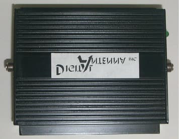
Click to zoom
Application Details
- Equipment Class
- AMP - Amplifier
- Date of Grant
- Apr 24, 2003
- Application Purpose
- Original Equipment
- Date of Application
- Apr 24, 2003
- Equipment Note
- Nextel/ GSM Dual Band Amplifier
- Frequency Range
- 896.00000000 - 901.00000000
- Company
- Digital Antenna Inc.
- Country
- United States
Documents & Files
Document Text
Text extracted from the exhibit documents filed with the FCC. Open a document above to read the original.
Users Manual
20 ft. cable provided FCC ID: PZODA4000N IC ID: 4260A-DA4000N 10 ft. cable provided 20 cm min. distance between antenna and persons 20 cm min. distance between antenna and persons For Nextel iDEN (QPSK), E-GSM & GSM-900 Amplifier Amplifier Cell phone Cell phone adapter cable Cell phone adapter cable or car kit Cell phone Typical Vehicle/Boat Installation User Instructions phone (954) 747-7022 fax (954) 747-7088 www.DigitalAntenna.com 5325 N.W. 108 th Avenue, Sunrise, FL 33351 ll Cell amplifier installation instructions. 1) Place the amplifier in a suitable location in the instrument console and plug the power cord into the cigarette socket or appropriate power jack. If hard wiring to a power block, be certain that the positive lead connects to the center pin of the amplifier power connector. Caution: The antenna(s) used for this transmitter must not be co-located or operating in conjunction with any other antenna or transmitter. Failure to observe the following restrictions will result in exceeding the FCC RF exposure limits. Antennas used for this transmitter must not exceed an antenna gain of 3 dBi with a minimum cable loss of 2.9 dB. For rear deck trunk and roof top installations, the antenna must be located at least 20 cm away from rear-seat passengers and bystanders in order to comply with the FCC RF exposure requirements. Antennas used for this transmitter must not exceed an antenna gain of 7 dBi with minimum cable loss of 5.4 dB. The antenna must be located at least 20 cm away from passengers in order to comply with the FCC RF exposure requirements. 3) Connect one end of the cell phone adapter cable to the amplifier were it is marked "phone" and the other end to the cell phones antenna port. 4) After you are certain that all connections are tight and secure, move the switch labeled "on/off" to the on position. A green light will illuminate indicating that the amplifier is ready for use. 2)"FCCRFExposureRequirements" (a)Vehicle-AntennaInstallation: (b)Boat-AntennaInstallation: : NOTEIt is normal for the amplifier to be warm during operation. This equipment has been tested and found to comply with the limits for a class B device, pursuant to Part 15 and the Specialized Mobile Radio Service authorized under subpart H of part 22 and part 90 of the FCC rules. These limits are designed to provide reasonable protection against harmful interference. This equipment generates, uses and can radiate radio frequency energy and, if not installed and used in accordance with this instruction manual, may cause harmful interference to radio communications, However there is no guarantee that interference will not occur in a particular installation. If this equipment does cause harmful interference to radio or other electronic reception, which can be determined by turning the equipment off and on, the user is encouraged to try to correct the interference by one of more of the following measures: Reorient or relocate the receiving antenna Increasetheseparationbetweentheequipmentandreceiver Connecttoisolatedpowerwithagroundcablegoingdirectlytothebatteryor DCsource Repositioningofthecoaxialcablemayalsoeliminateinterference. ConsultthedealeroranexperienceElectronicstechnicianforhelp. :ChangesormodificationsnotexpresslyapprovedbyDigitalAntenna, Inc.couldvoidtheuser'sauthoritytooperatetheequipment. l l l l l Donotcoil Warning Model #DA4000N Cellular Amplifier
Users Manual
20 ft. cable provided FCC ID: PZODA4000N IC ID: 4260A-DA4000N 10 ft. cable provided 20 cm min. distance between antenna and persons 20 cm min. distance between antenna and persons For Nextel iDEN (QPSK), E-GSM & GSM-900 Amplifier Amplifier Cell phone Cell phone adapter cable Cell phone adapter cable or car kit Cell phone Typical Vehicle/Boat Installation User Instructions phone (954) 747-7022 fax (954) 747-7088 www.DigitalAntenna.com 5325 N.W. 108 th Avenue, Sunrise, FL 33351 ll Cell amplifier installation instructions. 1) Place the amplifier in a suitable location in the instrument console and plug the power cord into the cigarette socket or appropriate power jack. If hard wiring to a power block, be certain that the positive lead connects to the center pin of the amplifier power connector. Caution: The antenna(s) used for this transmitter must not be co-located or operating in conjunction with any other antenna or transmitter. Failure to observe the following restrictions will result in exceeding the FCC RF exposure limits. Antennas used for this transmitter must not exceed an antenna gain of 3 dBi with a minimum cable loss of 2.9 dB. For rear deck trunk and roof top installations, the antenna must be located at least 20 cm away from rear-seat passengers and bystanders in order to comply with the FCC RF exposure requirements. Antennas used for this transmitter must not exceed an antenna gain of 7 dBi with minimum cable loss of 5.4 dB. The antenna must be located at least 20 cm away from passengers in order to comply with the FCC RF exposure requirements. 3) Connect one end of the cell phone adapter cable to the amplifier were it is marked "phone" and the other end to the cell phones antenna port. 4) After you are certain that all connections are tight and secure, move the switch labeled "on/off" to the on position. A green light will illuminate indicating that the amplifier is ready for use. 2)"FCCRFExposureRequirements" (a)Vehicle-AntennaInstallation: (b)Boat-AntennaInstallation: : NOTEIt is normal for the amplifier to be warm during operation. This equipment has been tested and found to comply with the limits for a class B device, pursuant to Part 15 and the Specialized Mobile Radio Service authorized under subpart H of part 22 and part 90 of the FCC rules. These limits are designed to provide reasonable protection against harmful interference. This equipment generates, uses and can radiate radio frequency energy and, if not installed and used in accordance with this instruction manual, may cause harmful interference to radio communications, However there is no guarantee that interference will not occur in a particular installation. If this equipment does cause harmful interference to radio or other electronic reception, which can be determined by turning the equipment off and on, the user is encouraged to try to correct the interference by one of more of the following measures: Reorient or relocate the receiving antenna Increasetheseparationbetweentheequipmentandreceiver Connecttoisolatedpowerwithagroundcablegoingdirectlytothebatteryor DCsource Repositioningofthecoaxialcablemayalsoeliminateinterference. ConsultthedealeroranexperienceElectronicstechnicianforhelp. :ChangesormodificationsnotexpresslyapprovedbyDigitalAntenna, Inc.couldvoidtheuser'sauthoritytooperatetheequipment. l l l l l Donotcoil Warning Model #DA4000N Cellular Amplifier
Cover Letter(s)
February 11, 2003 Federal Communications Commission 7435 Oakland Mills Road Columbia, MD 21046 U.S.A. Subject: Request to withhold the schematic diagrams and system block diagrams from public disclosure pursuant to an application for certification. Applicant: Digital Antenna, Inc. Product: Cellular amplifier Model: DA4000N FCC ID: PZO_______ID Dear Sir/Madam, Digital Antenna, Inc. respectfully request that the submitted schematic diagrams and block diagrams be withheld from public disclosure as per Section 0.459 of FCC rules. This request is made under the provisions of Section 0.457(d) of the commissions rules and section 552(b)(4) of the freedom of information Act. These sections authorize, as a withholding from public inspection, materials which would be privileged as a matter of law if retained by the person submitting them, and materials which would not customarily be released to the public by that person. The confidential materials are listed as follows: DA4000N Cell Amplifier Schematic. DA4000N Cell Amplifier Block Diagram. If you have any questions please contact us toll free at 877-433-7007. Sincerely, Anthony D. Gallagher President, Digital Antenna, Inc. phone (954) 747-7022 fax (954) 747-7088 www.DigitalAntenna.com 5325 N.W. 108th Avenue, Sunrise, FL 33351 ll
External Photos
DA4000N Label Photo DA4000N Logo phone (954) 747-7022 fax (954) 747-7088 www.DigitalAntenna.com 5325 N.W. 108th Avenue, Sunrise, FL 33351 ll DA4000N end plate photo “Antenna end” DA4000N End plate photo “Phone end” phone (954) 747-7022 fax (954) 747-7088 www.DigitalAntenna.com 5325 N.W. 108th Avenue, Sunrise, FL 33351 ll
ID Label/Location Info
DA4000N Label Photo DA4000N Logo phone (954) 747-7022 fax (954) 747-7088 www.DigitalAntenna.com 5325 N.W. 108th Avenue, Sunrise, FL 33351 ll
Internal Photos
DA4000N Cellular Amplifier Inside View Top View Bottom View phone (954) 747-7022 fax (954) 747-7088 www.DigitalAntenna.com 5325 N.W. 108th Avenue, Sunrise, FL 33351 ll
Operational Description
1 of 1 Technical Description DA4000N Variable Gain RF Amplifier Purpose: The purpose of the DA4000N Variable Gain bi-directional RF Amplifier is to boost the output power of a 600mw handheld cellular phone to a maximum legal limit of 3 watts for the 800 MHz iDEN (QPSK) and E-GSM & GSM-900 bands. Construction: The DA4000N circuit board has been designed with exceptional RF shielding. RF signal path construction, trace thickness, width and turning radii, complies with widely accepted high frequency specifications. The DA4000N is mounted to an aluminum mounting plate that performs as additional grounding as well as media to dissipate heat. A second aluminum plate is attached to the assembly, which further dissipates heat and provides a mounting mechanism to the extruded aluminum case. The extruded aluminum case is designed with top fins that provide appropriate surface area for heat dissipation. End plates close the assembly providing RFI shielding and a means to house connectors, switch and a power indicator. The function of the connectors, switch and power indicator is silk screened on the end plates for clarity. Functional Description: The DA4000N is a bi-directional variable gain RF amplifier. The direction of signal flow is described as Uplink (transmit to the antenna) and Downlink (receive from the antenna) for both 800 MHz iDEN band and E-GSM & GSM-900 bands. Uplink operating frequency is 806-821 MHz for the iDEN band, 880-890 MHz for the E-GSM band and 890-915 MHz for the GSM-900 band at 3 watts maximum output power. Uplink maximum gain is 8dB for the iDEN, E-GSM & GSM-900 bands. Downlink operating frequency is 851-866 MHz for iDEN, 925-935 MHz for E-GSM and 935-960 MHz for GSM-900 with a maximum gain of 15 dB. Signal protocol is iDEN (QPSK) and GSM. Use of the DA4000N is accomplished by connecting the antenna to the connector labeled “antenna” and the phone by way of a cell phone adapter cable to the connector labeled “phone”. Circuit operation: Uplink operation starts at the connector labeled J2 entering a diplexer (dip 2) with an input frequency range of 824-960 MHz. Two, 2 to 1 combiners separate uplink and downlink signal directions. An RF switch prevents Uplink from interfering with Downlink. A 10 dB attenuator (IC8) is used on the uplink path to reduce the input power of (IC1) to the allowable maximum of 60mw. Another 2 to 1 combiner (IC6) is used to separate uplink frequencies from downlink frequencies. Next is a diplexer (Dip 1) that is used to match the antenna impedance of 50 ohms. An RF switch prevents Uplink from interfering with Downlink. DC Power source: The DC4000N is designed to accept 12 to 24 VDC as an input. The normal maximum input current is 1 A. Switch SW1 enables power for two voltage regulator circuits after passing thru a 3A fuse F1. A 5VDC, 1.5A regulator VR2 provides regulated power to the bias circuitry Vapc. A 10VDC, 2A regulator VR1 provides regulated power to the 3 watt PA (IC1) for Vdd and the bias circuitry Vapc as well as bias circuitry for the LNA (IC3). phone (954) 747-7022 fax (954) 747-7088 www.DigitalAntenna.com 5325 N.W. 108th Avenue, Sunrise, FL 33351 ll
Parts List/Tune Up Info
Digital Antenna, Inc. Cell Amp DA4000N QtyDescription 1RF3108 RF Micro Devices 4AD8353 Analog Devices 2TOKO LTF3216D-F17S 2TOKO TDPH-902L-13 2TOKO TDPF-813E-13 1L78S05CV, 2A Regulator (TO-220) Tab Grd, ST Microelectronics 12KBP005, 50V, 2A Thru hole Bridge D-44 Package 1Green LED, Chicago Miniature Lamp, Inc, PN 4305H5 size 5mm 4100NH, SMT 603 PACKAGE, TOKO LLQ1608-AR10J 1.5pF, 50 VDC, SMT 402 11.5pF, 50 VDC, SMT 402 15.6pF, 50 VDC, SMT 402 233pF 50VDC, SMT 402, DK# PCC330CQCT-ND 4100pF 50VDC, SMT 402, DK# PCC101CQCT-ND 81000pF 50VDC, SMT 402, PCC1721CT-ND 410000 pF 50vdc, SMT 402, DK# PCC103BQCT-ND 2.47uF 16VDC, SMT 603, DK# PCC1792CT-ND 11uF, 16VDC SMT 603 Package 13.3 uF, 16VDC SMCTB Package 1100uF 50vdc, Radial lead Panasonic ECA-1HM101 22.7 ohm SMT 805 447 ohm SMT 805 482 ohm SMT 805 291 ohm SMT 805 1180 ohm SMT 805 1200 ohm SMT 805 2270 ohm SMT 805 2820 ohm SMT 805 41.74K ohm SMT 805 1DC Power Jack, CUI Stack# PJ-102A, DK# CP-102A-ND 2Chinmore Ind PN 054MV 1RD1# TS-16PS-M6 (Stock Electronics) 1CELL AMP DA4000 REV G1 1ALUMINUM CASE Die# DIG-H-2 1P/N 070602 REV A 1P/N 070702 REV A 1Cigarette Lighter/DC Plug Assy phone (954) 747-7022 fax (954) 747-7088 www.digitalantenna.com 5325 N.W. 108 th Avenue, Sunrise, FL 33351 ll
Parts List/Tune Up Info
Tuning Procedure There are no tuning procedures. Manufacturing tolerances have been designed so that an accumulation of worst case component variation will not exceed the allowable output power of 3 watts.
RF Exposure Info
4/16/2003 Page 1 of 3 FCCID: PZODA4000N FCC RF Exposure Requirements General information: FCCID: PZODA4000N Device category: Mobile per Part 2.1091 Environment: General Population/Uncontrolled Exposure Mobile devices that operate in the Cellular Radiotelephone Service and the Specialized Mobile Radio Service authorized under subpart H of part 22 and part 90 of this chapter are subject to routine environmental evaluation for RF exposure prior to equipment authorization or use if they operate at frequencies of 1.5 GHz or below and their effective radiated power (ERP) is 1.5 watts or more. However, compliance with the power density limits of 1.1310 is required. Antenna: The manufacturer does not specify any antenna to be used with this device. This device has provisions for operation in a vehicle, a boat or a fixed location. Configuration Antenna p/n Type Max. Gain (dBi) Passenger car Any - 3 Boat Any - 7dBi (5dBd) Fixed Any - 7dBi (5dBd) Operating configuration and exposure conditions: The conducted output power is 2.8 watt. iDEN modulation qualifies for a maximum duty cycle factor is 67.5%, which yields an EIRP of 1.89W with a 0dBi antenna gain and no cable loss. Part 2.1091 states that devices are excluded from routine evaluation if the EIRP is less than 2.46Watt (or 1.5WERP). GSM qualifies for a crest factor of 3 which is not the worst-case operating configuration. - Vehicle Operation: The maximum antenna gain that can be used is 3dBi. A coaxial cable of the type RG174 has a loss of 2.9dB for a length of 10 feet. Therefore, the EIRP is 1.89Watt. - Boat Operation: Cable length = 20 ft exposed and 3 feet internal to radom = 23 ft. Total. 23 feet cable loss including connector insertion loss at 800-900MHz is 5.4 dB. The maximum antenna gain that can be used is 5dBd. Therefore, the EIRP is 1.89Watt. 4/16/2003 Page 2 of 3 FCCID: PZODA4000N MPE Calculation: The minimum separation distance is calculated as follows: The limit for general population/uncontrolled exposure environment below 1500MHz is 0.54mW/cm2 for the worst-case frequency. Channel Frequency: 806 MHz The conducted power output is 2.8 watt. Max. Antenna Gain (dBi) / Minimum Cable Loss (dB) Power Density at 20 cm distance 3dBi / 2.9dB 5dBd / 5.4dB - Power EIRP (W) Duty Cycle (%) (mW/cm 2 ) (mW/cm 2 ) (mW/cm 2 ) 1.89 67.5 (iDEN) 0.38 0.54* - 0.93 33.3 (GSM) 0.19 0.27 - *The calculated MPE distance is 20.0cm for 1.6dB gain Conclusion: The device complies with the MPE requirements by providing a safe separation distance of 20 cm between the antenna, including any radiating structure, and any persons when normally operated . Proposed RF exposure safety information to include in User’s Manual: “FCC RF Exposure Requirements: CAUTION: The antenna(s) used for this transmitter must not be co-located or operating in conjunction with any other antenna or transmitter. This device is approved with emissions having a source-based time-averaging duty factor not exceeding 67.5%. Vehicle – Antenna Installation: - Antennas used for this transmitter must not exceed an antenna gain of 3 dBi with a minimum cable loss of 2.9dB. 4/16/2003 Page 3 of 3 FCCID: PZODA4000N - For rear deck trunk and roof top installations, the antenna must be located at least 20 cm away from rear-seat passengers and bystanders in order to comply with the FCC RF exposure requirements. Boat – Antenna Installation: - Antennas used for this transmitter must not exceed an antenna gain of 5dBd(7dBi) with a minimum cable loss of 5.4dB. - The antenna must be located at least 20 cm away from passengers in order to comply with the FCC RF exposure requirements. Failure to observe these restrictions will result in exceeding the FCC RF exposure limits. ~~~~~~~~~~~~~~~ FYI - Draft/Grant notes – RF exposure: TCB Section D: Mobile transmitters identified in §2.1091 that satisfy Categorical Exclusion Requirements of §2.1091: ... The antenna installation and operating configurations of this transmitter, including any applicable source-based time-averaging duty factor, antenna gain and cable loss must satisfy MPE categorical Exclusion Requirements of §2.1091. The antenna(s) used for this transmitter must be installed to provide a separation distance of at least 20 cm from all persons and must not be co-located or operating in conjunction with any other antenna or transmitter. Users and installers must be provided with antenna installation instructions and transmitter operating conditions for satisfying RF exposure compliance.
Contact Information
Applicant
Anthony Gallagher(President)
Test Firm
Timco Engineering, Inc.S Sanders
Technical Specifications
| # | Rule Parts | Frequency Range | Power Output | Emission | Tolerance |
|---|---|---|---|---|---|
| 3 | 9 | 896 MHz - 901 MHz | 2.8 W | D7W | Amp |
Other Applications from Digital Antenna Inc.
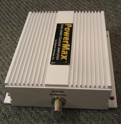
PZODA4000SBR
Jun 13, 2004Dual Band Bi-Directional Booster
Equipment Class
PCB - PCS Licensed Transmitter