PZODA4000SBRDual Band Bi-Directional Booster
Digital Antenna Inc.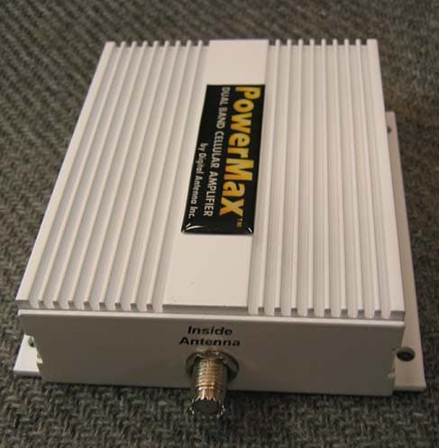
Click to zoom
Application Details
- Equipment Class
- PCB - PCS Licensed Transmitter
- Date of Grant
- Jun 13, 2004
- Application Purpose
- Original Equipment
- Date of Application
- Jun 13, 2004
- Equipment Note
- Dual Band Bi-Directional Booster
- Frequency Range
- 869.00000000 - 895.00000000
- Company
- Digital Antenna Inc.
- Country
- United States
Documents & Files
Document Text
Text extracted from the exhibit documents filed with the FCC. Open a document above to read the original.
Users Manual
INSTALLATION AND OPERATION MANUAL 1. Package Contents................................................................................ 2 2. Important Safety Information.................................................................. 2 a. Limited Warranty................................................................ 3 b. Limitation on Liability........................................................... 3 c. FCC Regulations.................................................................. 3 3. Pre-installation Guidelines...................................................................... 3 a. Installation Tools.................................................................. 3 b. Installation Procedure............................................................ 4 c. Electrical Power................................................................... 5 d. Amplifier/Repeater Status....................................................... 5 e. In-building Coverage Problems................................................. 6 f. Coaxial Cable Recommendations............................................... 7 4. Home/Office Installation........................................................................ 8 5. Marine Installation............................................................................... 9 6. RV Installation.................................................................................. 10 7. Electrical Specifications....................................................................... 11 8. Antenna & Accessory Options............................................................... 12 9. Technical Support.............................................................................. 13 1 2 R I I M M P P O O R R T T A A N N T T R e e a a d d i i n n s s t t r r u u c c t t i i o o n n s s c c o o m m p p l l e e t t e e l l y y b b e e f f o o r r e e a a t t t t e e m m p p t t i i n n g g i i n n s s t t a a l l l l ! ! 1. Package Contents Part Number Description DA4000SBR Dual Band Wireless Cellular Amplifier/Repeater 288-PB Outside omni-directional 9dB gain dual band cell antenna 135-RD Inside omni-directional dual band cell antenna with stand & 18” cable DP515 12 VDC to 5 VDC power cable DP255 110-240 VAC to 5 VDC power supply C277-30 30' PowerMax TM ULTRA low loss cable DH288 Stainless steel mounting hardware: qty 2 U-bolts, nuts, washers; qty 4 philips head screws 2. Important Safety Information The DA4000SBR system complies with all FCC, IC, UL rules, regulations and codes. Follow all guidelines in the installation and instruction manual and read completely before beginning the installation procedure. Do not deviate or disregard any of the safety features included in the manual or with the equipment, nor operate the system in an unintended application. WARNING! Only Digital Antenna authorized products may be used with the DA4000SBR system. Using unauthorized equipment with the DA4000SBR system will harm the system, voids the warranty and can be detected in the event of a failure. WARNING! Do not install antenna near power lines. Contact with any high voltage power lines could result in shock or loss of life. WARNING! Handle all electronic parts with care. Dropping or mishandling the DA4000SBR amplifier/repeater, antennas or power supplies can damage sensitive RF and electronic components. 3 a. LIMITED WARRANTY Digital Antenna, Inc. warrants marine antennas for five (5) years and cellular antennas and amplifiers for one (1) year that its Products sold hereunder will at the time of shipment be free from defects in material and workmanship and will conform to Digital Antenna’s applicable specifications or, if appropriate, to Customer’s specifications previously accepted by Digital Antenna in writing. If products sold hereunder are not as warranted, Digital Antenna shall, at its option either refund the purchase price, or repair or replace the product, provided proof of purchase and written notice of nonconformance are received by Digital Antenna within five (5) or one (1) years of date of purchase and provided said nonconforming Products are, with Digital Antenna’s written authorization, returned in protected shipping containers. Digital Antenna will pay for transporting the repaired or exchanged product to Customer. This warranty shall not apply to any Products Digital Antenna determined to have been, by Customer otherwise, subjected to mishandling, misuse, neglect, improper testing, repair alteration, damage, assembly or processing that alters physical or electrical properties. b. LIMITATION ON LIABILITY In no event shall Digital Antenna, Inc. Be liable for any direct, indirect, special, punitive, incidental, exemplary or consequential damages, or any damages whatsoever, even if Digital Antenna, Inc. Has been previously advised of the possibility of such damages, whether in an action under contract, negligence, or any other theory, arising out of or in connection with the use, inability to use, or performance of the information, services, products, and materials available from this manual. These limitations shall apply notwithstanding any failure of essential purpose of any limited remedy. Because some jurisdictions do not allow limitations on how long an implied warranty lasts, or the exclusion or limitation of liability for consequential or incidental damages, the above limitations may not apply to you. c. FCC REGULATIONS FCC ID: PZODA4000SBR This equipment has been tested and found to comply with the limits for a class B device, pursuant to Part 15 of the FCC rules. These limits are designed to provide reasonable protection against harmful interference. This equipment generates, uses and can radiate radio frequency energy and if not installed and used in accordance with this instruction manual, may cause harmful interference to radio communications, However, there is no guarantee that interference will not occur in a particular installation. If this equipment doe…
Text truncated - open the document above for the full version.
Attestation Statements
1 Bruno From: Bruno [[email protected]] Sent: Friday, April 23, 2004 4:43 PM To: [email protected] Cc: Sharon Hoffman Subject: RE: DA4000SBR FCC & IC Certification AMP_booster_repe ater_revfinal_... Bud, Thank you for the info and tentative shipping date. As we discussed today, you will find a document from the FCC concerning harmonization of amplifier requirements. This document was published in March 2004. .../... Best Regards, Bud Gallagher Digital Antenna, Inc. 2002/2003 NMEA Marine Antenna Product award winner2003 NMEA Cell Amplifier Product award winner [email protected] 954-747-7022 ext 202 2
Cover Letter(s)
May 25, 2004 Federal Communications Commission 7435 Oakland Mills Road Columbia, MD 21046 U.S.A. Subject: Request to withhold the schematic diagrams and system block diagrams from public disclosure pursuant to an application for certification. Applicant: Digital Antenna, Inc. Product: Cellular amplifier/Repeater Model: DA4000SBR FCC ID: PZODA4000SBR Dear Sir/Madam, Digital Antenna, Inc. respectfully request that the submitted schematic diagrams and block diagrams be withheld from public disclosure as per Section 0.459 of FCC rules. This request is made under the provisions of Section 0.457(d) of the commissions rules and section 552(b)(4) of the freedom of information Act. These sections authorize, as a withholding from public inspection, materials which would be privileged as a matter of law if retained by the person submitting them, and materials which would not customarily be released to the public by that person. The confidential materials are listed as follows: DA4000SBR Cell Amplifier Schematic. DA4000SBR Cell Amplifier Block Diagram. If you have any questions please contact us toll free at 877-433-7007. Sincerely, Anthony D. Gallagher President, Digital Antenna, Inc. phone (954) 747-7022 fax (954) 747-7088 www.DigitalAntenna.com 5325 N.W . 108th Avenue, Sunrise, FL 33351 zz
Cover Letter(s)
1 Gretchen Torres From: J2 [[email protected]] Sent: Monday, March 03, 2008 5:27 PM To: 'Bruno Clavier' Cc: Bud Subject: RE: TIMCO -- FCC audit of FCCID: PZODA4000SBR FCC RT: 48784 Hello Bruno, Hope things are going well there also. I have not ignored this, just doing some research. After having spent several hours in the lab redoing measurements and reading all the info you sent, I think your answer is well conceived and appropriate. If they are responding to a complaint filing, why do they not disclose the complaining party? Isn't this supposed to be open info paid with tax dollars. Regards, John -----Original Message----- From: Bruno Clavier [mailto:[email protected]] Sent: Friday, February 29, 2008 4:27 PM To: John Jones Cc: Gretchen Torres Subject: TIMCO -- FCC audit of FCCID: PZODA4000SBR FCC RT: 48784 Importance: High Hi, John: Hope that you are doing well. The FCC has just sent us a request for technical information (RT) for this bi-directional booster. It is likely that this inquiry from the FCC is the result of a competitor's complaint because of the age of the approval (June 2004!!). We need to address it as soon as possible. I have a few ideas, but I would like to hear your comments, if any. You can call me if you would like to discuss further. I have attached relevant documents: Test report, FCC policy on boosters, and the FCC RT. Thanks and Regards, Bruno Proposed reply under review...please feel free to critic. The Amp-Booster Policy Guidelines states that "Occupied bandwidth - Use RBW 300 Hz or 1% RBW. The spectral shape of the output should look similar to input for all modulations. " This is a subjective requirement. Considering the 99% emission bandwidth only, the spectral shape of the output matches that of the input. It is shown on these calibrated plots that the output signal complies with the band-edge limit of -13dBm. ~~~~~~~~` 2 Best Regards, Bruno Clavier TIMCO ENGINEERING INC. 849 NW State Road 45 Newberry, Florida 32669 http://www.timcoengr.com 352-472-5500 F 352.472.2030 mailto:[email protected] ~~~~~~~~~~~~~~~~~~~~~~~~~~~~~~~~~~~~~~~~~~~~~~~~~~~~~~~~~~~~~~~~ Privileged/Confidential Information may be contained in this message. If you are not the addressee indicated in this message (or responsible for delivery of the message to such person), you may not copy or deliver this message to anyone. In such case, you should destroy this message and kindly notify the sender by reply email. Please advise immediately if you or your employer do not consent to Internet email for messages of this kind. Opinions, conclusions and other information in this message that do not relate to the official business of my firm shall be understood as neither given nor endorsed by it.
External Photos
DA4000SBR end plate photo “Outside Antenna end” DA4000SBR End plate photo “Inside Antenna end” phone (954) 747-7022 fax (954) 747-7088 www.DigitalAntenna.com 5325 N.W . 108th Avenue, Sunrise, FL 33351 zz
ID Label/Location Info
DA4000SBR Label Photo DA4000SBR Logo phone (954) 747-7022 fax (954) 747-7088 www.DigitalAntenna.com 5325 N.W . 108th Avenue, Sunrise, FL 33351 zz
Internal Photos
DA4000SBR Cellular Amplifier/Repeater Inside View Top View BottomView phone (954) 747-7022 fax (954) 747-7088 www.DigitalAntenna.com 5325 N.W . 108th Avenue, Sunrise, FL 33351 zz
Operational Description
1 of 2 Technical Description DA4000SBR Variable Gain RF Amplifier/Repeater Purpose: The purpose of the DA4000SBR Variable Gain bi-directional RF Amplifier/Repeater is to boost the output power of a .6 watt handheld cellular phone to a maximum legal limit of 3 watts for the 800 MHz cellular band and 2 watts for the 1800- 1900 MHz PCS band. Digital Antenna, Inc. manufactures a line of 9dBi gain cellular antennas to be used with the DA4000SBR amplifier/Repeater. The 9dBi antennas are different in outside housing only. The same dual band, tri mode element is used for all Digital Antenna, Inc. cellular antennas. Construction: The DA4000SBR circuit board has been designed with exceptional RF shielding. RF signal path construction, trace thickness, width and turning radii, complies with widely accepted high frequency specifications. The extruded aluminum case is designed with top fins that provide appropriate surface area for heat dissipation. End plates close the assembly providing RFI shielding and a means to house connectors, switch and a power indicator. The function of the connectors, switch and power indicator is silk screened on the end plates for clarity. Functional Description: The DA4000SBR is a bi-directional variable gain RF amplifier/Repeater. The direction of signal flow is described as Uplink (transmit to the antenna) and Downlink (receive from the antenna) for both 800 MHz cellular band and 1800- 1900 PCS bands. Uplink operating frequency is 824-849 MHz for cellular at 3 watts maximum output power and 1850- 1910 MHz for PCS at 2 watts maximum output power. Uplink maximum gain for the cellular band is 55 dB and the PCS band is 55 dB. Downlink operating frequency is 869-894 MHz for cellular with a maximum gain of 60 dB and 1930-1990 MHz for PCS with a maximum gain of 60 dB. Signal protocol is TDMA, CDMA, GSM850, GSM1900, AMPS, GPRS and PCS. Use of the DA4000SBR is accomplished by connecting an outside antenna to the connector labeled “outside antenna”. The phone communicates with the DA4000SBR by way of the inside antenna thru the air. A tri-color LED provides a visual activity indication. Green indicates that power is on and the unit is ready. Blinking amber indicates RF phone activity. Red indicates either heavy RF phone activity or a malfunction. Continued red requires system shutdown. An output power control circuit is incorporated to prevent stray power from being produced in case of a malfunction. Circuit operation: Uplink operation starts at the connector labeled J2 entering a diplexer with an input frequency range of 824-894 MHz for cellular and 1850-1990 MHz for PCS. Two duplexers separate uplink and downlink signal directions. One duplexer is used for cellular with a frequency range of 810-960 MHz and the other duplexer is used for PCS with a frequency response of 1710-1990 MHz. An RF band pass filter network with a center frequency of 836 MHz is used on the input to the 3 watt amplifier. Another duplexer is used to separate cellular uplink frequencies from cellular downlink frequencies. Next is a diplexer that is used to separate the cellular band from the PCS band of frequencies. 2 of 2 An RF band pass filter network with a center frequency of 1880 MHz is used on the input to the 2 watt amplifier. Another duplexer is used to separate PCS uplink frequencies from PCS downlink frequencies. Next is a diplexer that is used to separate the Cellular band from the PCS band of frequencies. Downlink operation starts at the connector entering a diplexer with an input frequency range of 824-894 MHz for cellular and 1850-1990 MHz for PCS. Two duplexers separate uplink and downlink signal directions. One duplexer is used for cellular with a frequency range of 810-960 MHz and the other duplexer is used for PCS with a frequency response of 1710-1990 MHz. A band Pass filters network with a center frequency of 1960 MHz and band pass filter network with a center frequency of 881 MHz, provide frequency isolation to the input of a low noise amplifiers. The LNA’s then drives into duplexers with a frequency range of 1710-1990 MHz and a duplexer for cellular with a frequency range of 810-960 MHz. As mentioned before, these duplexers separate uplink from downlink signal paths. Next a set of duplexers interface to a Diplexer (dip 2) which finally feeds the phone thru the inside antenna connected to a mini-UHF connector. This completers the downlink path to the cell phone. DC Power source: The DA4000SBR is designed to accept 5 VDC as an input. The normal maximum input current is 1 A. Switch SW1 enables power . phone (954) 747-7022 fax (954) 747-7088 www.DigitalAntenna.com 5325 N.W . 108th Avenue, Sunrise, FL 33351 zz
Parts List/Tune Up Info
Digital Antenna, Inc. Cell Amp DA4000-SBR PCB REV SBR12 2-Feb-04 DesignatorQtyDescription U191RF3108 RF Micro Devices U1,2,11,12,13,17,18,2213Mini Circuits MNA-5 23,26,27,28,30 U20,212TOKO LTF3216D-F17S U3,4,5,6,7,8,9,10,15,1610TOKO TDPH-1880L-13 U24,25,31,32,33,34,35,3610TOKO TDPF-836E-13 37,38 D11Green LED, Chicago Miniature Lamp, Inc, PN 4305H5 size 5mm C31.5pF, 50 VDC, SMT 402 C1115.6pF, 50 VDC, SMT 402 C5,9161000pF 50VDC, SMT 402, PCC1721CT-ND U1C2,U2C2,U11C2,U12C2, U13C2,U14C2,U17C2,U18C2 U22C2,U23C2,U26C2,U27C2 U28C2,U30C2 U1C1,U2C1,U11C1,U12C1,14100pF 50VDC, SMT 402 U13C1,U14C1,U17C1,U18C1 U22C1,U23C1,U26C1,U27C1 U28C1,U30C1 C4,7,8,12410000 pF 50vdc, SMT 402, DK# PCC103BQCT-ND C1011uF, SMT 603 Package C6,1423.3 uF, 16VDC SMCTB Package C1,22100uF 50vdc, Radial lead Panasonic ECA-1HM101 U1R1,U2R1,U11R1,U12R1,1433 ohm SMT 603 U13R1,U14R1,U17R1,U18R1 U22R1,U23R1,U26R1,U27R1 U28R1,U30R1 R12,1522.7 ohm SMT 402 R1,2,3,4,6,7,8,9,21,22,23,241650 ohm SMT 603 25,26,27,28 V1,221K Potentiometer, Series TC03 Cermet, DK# TC03X-102ETR-ND R171180 ohm SMT 402 R51200 ohm SMT 402 R19,202270 ohm SMT 402 R13,142820 ohm SMT 402 R10,11,16,1841.74K ohm SMT 402 POWER1DC Power Jack, CUI Stack# PJ-102B, DK# CP-102B-ND J1,22Chinmore Ind PN 054MV SW11RD1# TS-16PS-M6 (Stock Electronics) PCB1SBR DA4000-SBR REV SBR12 CASE1ALUMINUM CASE Die# DIG-H-2 Painted white END PLATE 1 SBR1P/N 020504 REV A END PLATE 2 SBR1P/N 020404 REV A Proprietary Information, Property of Digital Antenna, Inc. 2004 phone (954) 747-7022 fax (954) 747-7088 www.digitalantenna.com 5325 N.W. 108 th Avenue, Sunrise, FL 33351 zz
Parts List/Tune Up Info
1 of 2 Technical Description DA4000SBR Variable Gain RF Amplifier/Repeater Purpose: The purpose of the DA4000SBR Variable Gain bi-directional RF Amplifier/Repeater is to boost the output power of a .6 watt handheld cellular phone to a maximum legal limit of 3 watts for the 800 MHz cellular band and 2 watts for the 1800- 1900 MHz PCS band. Digital Antenna, Inc. manufactures a line of 9dBi gain cellular antennas to be used with the DA4000SBR amplifier/Repeater. The 9dBi antennas are different in outside housing only. The same dual band, tri mode element is used for all Digital Antenna, Inc. cellular antennas. Construction: The DA4000SBR circuit board has been designed with exceptional RF shielding. RF signal path construction, trace thickness, width and turning radii, complies with widely accepted high frequency specifications. The extruded aluminum case is designed with top fins that provide appropriate surface area for heat dissipation. End plates close the assembly providing RFI shielding and a means to house connectors, switch and a power indicator. The function of the connectors, switch and power indicator is silk screened on the end plates for clarity. Functional Description: The DA4000SBR is a bi-directional variable gain RF amplifier/Repeater. The direction of signal flow is described as Uplink (transmit to the antenna) and Downlink (receive from the antenna) for both 800 MHz cellular band and 1800- 1900 PCS bands. Uplink operating frequency is 824-849 MHz for cellular at 3 watts maximum output power and 1850- 1910 MHz for PCS at 2 watts maximum output power. Uplink maximum gain for the cellular band is 55 dB and the PCS band is 55 dB. Downlink operating frequency is 869-894 MHz for cellular with a maximum gain of 60 dB and 1930-1990 MHz for PCS with a maximum gain of 60 dB. Signal protocol is TDMA, CDMA, GSM850, GSM1900, AMPS, GPRS and PCS. Use of the DA4000SBR is accomplished by connecting an outside antenna to the connector labeled “outside antenna”. The phone communicates with the DA4000SBR by way of the inside antenna thru the air. A tri-color LED provides a visual activity indication. Green indicates that power is on and the unit is ready. Blinking amber indicates RF phone activity. Red indicates either heavy RF phone activity or a malfunction. Continued red requires system shutdown. An output power control circuit is incorporated to prevent stray power from being produced in case of a malfunction. Circuit operation: Uplink operation starts at the connector labeled J2 entering a diplexer with an input frequency range of 824-894 MHz for cellular and 1850-1990 MHz for PCS. Two duplexers separate uplink and downlink signal directions. One duplexer is used for cellular with a frequency range of 810-960 MHz and the other duplexer is used for PCS with a frequency response of 1710-1990 MHz. An RF band pass filter network with a center frequency of 836 MHz is used on the input to the 3 watt amplifier. Another duplexer is used to separate cellular uplink frequencies from cellular downlink frequencies. Next is a diplexer that is used to separate the cellular band from the PCS band of frequencies. 2 of 2 An RF band pass filter network with a center frequency of 1880 MHz is used on the input to the 2 watt amplifier. Another duplexer is used to separate PCS uplink frequencies from PCS downlink frequencies. Next is a diplexer that is used to separate the Cellular band from the PCS band of frequencies. Downlink operation starts at the connector entering a diplexer with an input frequency range of 824-894 MHz for cellular and 1850-1990 MHz for PCS. Two duplexers separate uplink and downlink signal directions. One duplexer is used for cellular with a frequency range of 810-960 MHz and the other duplexer is used for PCS with a frequency response of 1710-1990 MHz. A band Pass filters network with a center frequency of 1960 MHz and band pass filter network with a center frequency of 881 MHz, provide frequency isolation to the input of a low noise amplifiers. The LNA’s then drives into duplexers with a frequency range of 1710-1990 MHz and a duplexer for cellular with a frequency range of 810-960 MHz. As mentioned before, these duplexers separate uplink from downlink signal paths. Next a set of duplexers interface to a Diplexer (dip 2) which finally feeds the phone thru the inside antenna connected to a mini-UHF connector. This completers the downlink path to the cell phone. DC Power source: The DA4000SBR is designed to accept 5 VDC as an input. The normal maximum input current is 1 A. Switch SW1 enables power . phone (954) 747-7022 fax (954) 747-7088 www.DigitalAntenna.com 5325 N.W. 108th Avenue, Sunrise, FL 33351 zz
RF Exposure Info
FCC RF Exposure Requirements General information: FCCID: PZODA4000SBR Device category: Mobile per Part 2.1091 and Fixed per part 1.1307 Environment: General Population/Uncontrolled Exposure Mobile devices that operate in the Personal Communication Service authorized under subpart H of part 22 and subpart E of part 24 are subject to routine environmental evaluation for RF exposure prior to equipment authorization or use if they operate at frequencies of 1.5 GHz or below and their effective radiated power (ERP) is 1.5 watts (2.46WEIRP) or more, or if they operate at frequencies above 1.5 GHz and their ERP is 3 watts (4.92WEIRP) or more. Otherwise, compliance with the power density limits of 1.1310 is required. Antenna: This device has provisions for operation in a vehicle type RV, a boat, or at a fixed location. Configuration Antenna p/n Type Max. Gain (dBi) RV * Omni 9 Boat * Omni 9 Fixed Outdoor** * * 9 Fixed Indoor * * 0 * Antenna part number are listed in the User’s/Installations manual. ** For outdoor antenna the antenna(s) used for this transmitter must be fixed-mounted on outdoor permanent structures. RF exposure compliance is addressed at the time of licensing, as required by the responsible FCC Bureau(s), including antenna co-location requirements of §1.1307(b)(3). Operating configuration and exposure conditions: Output Power: Frequency band Modulation MAX Output power Uplink (dBm) MAX Output power Downlink (dBm) GSM 32.5 10 CDMA 22.2 10.2 AMPS band TDMA 28.9 9.9 GSM 28 10 CDMA 28.1 10 PCS band TDMA 26.8 10 6/14/2004 Page 1 of 3 FCCID: PZODA4000SBR The maximum conducted output power for the downlink bands is 10mW. The maximum EIRP is 10mW for the unity gain antenna as specified in this filing. The maximum conducted output power for the uplink PCS and AMPS bands are respectively 646mW and 1.8W. - RV/Boat Operation: Cable P/N C277-30 • Length: 30’ (9.14m) • Impedance: 50 Ohm • RF connectors: N male and mini-UHF male factory attached • Attenuation at 800 MHz: 4.5 dB per 30’ • Attenuation at 1900 MHz: 7.5 dB per 30’ The Omni antenna rated at 9dBi, if mounted with a "perfect ground" will compute to a real 9dBi+. However, in the applications to which they are being used the real measurement has to be made as one in free space. Particularly, for the 836MHz (mid-uplink-freq) area that we are concerned with, the wavelength is approximately 14". The antenna is mounted free air at a level of 10' or more above ground, approximately 8.5 wavelengths above a usable ground, and in the vicinity of fiberglass. Virtually any antenna mounted higher than 3 wavelengths above ground receives no benefit of the ground wave/director action of a grounded antenna, therefore a free space rating for the antenna is much more appropriate. The free space rating for this antenna at the 836MHz band is 5.75dBi. Considering it is connected with a cable having a 4.5dB loss, the resultant gain is 1.25dB. Added to the output power at 32.5dBm (1.8W), this results in 33.75dB EIRP, (2.35W), below the limit of 2.46WEIRP. MPE Calculation: The minimum separation distance is calculated as follows: The limit for general population/uncontrolled exposure environment below 1500MHz is 0.55mW/cm2 for the worst-case frequency, which is Channel Frequency: 824 MHz 6/14/2004 Page 2 of 3 FCCID: PZODA4000SBR The limit for general population/uncontrolled exposure environment is 1mW/cm2 above 1500MHz. Max. Antenna Gain (dBi) / Minimum Cable Loss (dB) Power Density at 20 cm distance 0dBi (indoor)/0dB 9dBi(RV/boat)/ 4.5dB(800) & 7.5dB(1900) - Freq (MHz) Power EIRP (W) Duty Cycle (%) (mW/cm 2 ) (mW/cm 2 ) (mW/cm 2 ) 824 0.010 100 0.002 - - 824 2.371 100 - 0.47 - 1880 0.912 100 - 0.18 - Conclusion: The device complies with the MPE requirements by providing a safe separation distance of 20 cm between the antenna, including any radiating structure, and any persons when normally operated. 6/14/2004 Page 3 of 3 FCCID: PZODA4000SBR
Test Report
APPLICANT: DIGITAL ANTENNA FCC ID: PZODA4000SBR REPORT #: D\DigitalAntenna_PZO\658AUT4\658AUT4TestReport.doc COVER PAGE FCC Test Report Bi-Directional Booster Part 22 and part 24 Product Name: POWERMAX DUAL BAND CELLULAR AMPLIFIER FCC ID: PZODA4000SBR Applicant: DIGITAL ANTENNA 5325 NW 108TH AVENUE SUNRISE FL 33351 Date Receipt: 5/10/2004 Date Tested: 5/26/2004 PLEASE NOTE: THE ATTACHED REPORT SHALL NOT BE REPRODUCED EXCEPT IN FULL WITHOUT THE WRITTEN APPROVAL OF TIMCO ENGINEERING, INC. APPLICANT: DIGITAL ANTENNA FCC ID: PZODA4000SBR REPORT #: D\DigitalAntenna_PZO\658AUT4\658AUT4TestReport.doc TABLE OF CONTENTS TABLE OF CONTENTS 1 COMPLIANCE STATEMENT:............................................................................................................................1 2 GENERAL INFORMATION - part 2.1033 (c) ....................................................................................................2 3 Part 2.1046(a) RF power output: ...........................................................................................................................4 4 Part 2.1049 Gain ....................................................................................................................................................5 5 Part 2.1049 Input/Output modulated amplitude comparison – AMPS band..........................................................7 5.1 Uplink – GSM 824.2Mhz ..............................................................................................................................7 5.2 Uplink – GSM 848.8Mhz ..............................................................................................................................8 5.3 Downlink – GSM 869.2Mhz .........................................................................................................................9 5.4 Uplink – CDMA 824.7Mhz .........................................................................................................................10 5.5 Uplink – CDMA 848.31Mhz .......................................................................................................................11 5.6 Downlink – CDMA 894.31Mhz ..................................................................................................................12 5.7 Uplink – TDMA 824.04Mhz .......................................................................................................................13 5.8 Uplink – TDMA 848.97Mhz .......................................................................................................................14 5.9 Downlink – TDMA 869.04Mhz ..................................................................................................................15 6 Part 2.1049 Input/Output modulated amplitude comparison – PCS band ...........................................................16 6.1 Uplink – GSM 1850.2Mhz ..........................................................................................................................16 6.2 Uplink – GSM 1909.8Mhz ..........................................................................................................................17 6.3 Downlink – GSM 1930.2Mhz .....................................................................................................................18 6.4 Uplink – CDMA 1851.25Mhz .....................................................................................................................19 6.5 Downlink – CDMA 1931.25Mhz ................................................................................................................20 6.6 Uplink – TDMA 1850.04Mhz .....................................................................................................................21 6.7 Uplink – TDMA 1909.97Mhz .................................................................................…
Text truncated - open the document above for the full version.
Contact Information
Applicant
Anthony Gallagher(President)
Test Firm
Timco Engineering, Inc.S Sanders
Technical Specifications
| # | Rule Parts | Frequency Range | Power Output | Emission | Tolerance |
|---|---|---|---|---|---|
| 16 | 22H | 869 MHz - 895 MHz | 10.00 mW | DXW | Amp |
Other Applications from Digital Antenna Inc.
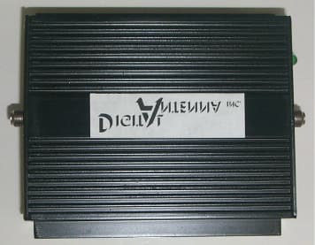
PZODA4000N
Apr 24, 2003Nextel/ GSM Dual Band Amplifier
Equipment Class
AMP - Amplifier