FCCID.CO- FCC ID Database
HomeCompaniesEquipment ClassesSearch

© 2026 FCC ID Database. All rights reserved.

AboutContactData sourced from FCC public records
  1. Home/
  2. Fidelity Comtech, Inc./
  3. Q2A-FCI2400

Q2A-FCI2400Wireless LAN System with Amplifier

Fidelity Comtech, Inc.
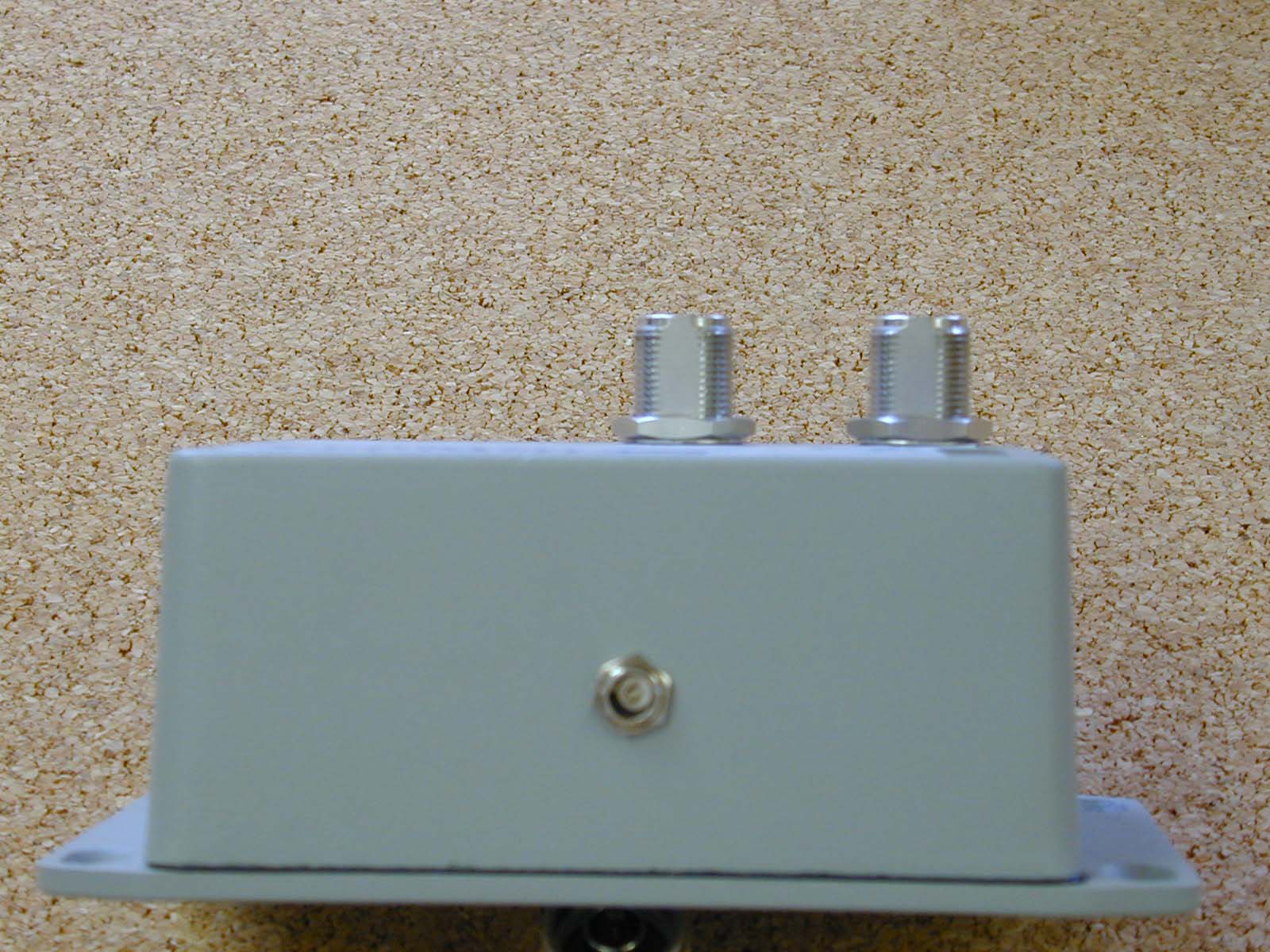
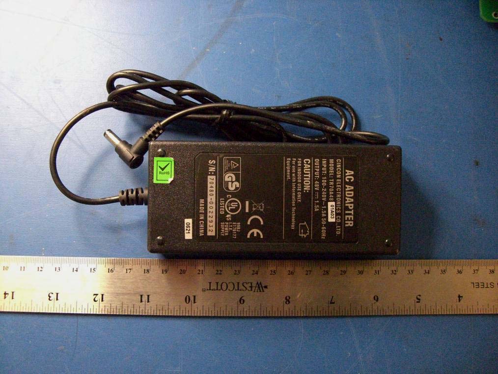
Wireless LAN System with Amplifier - FCC ID Q2A-FCI2400 - Fidelity Comtech, Inc.
Click to zoom

Application Details

Equipment Class
DTS - Digital Transmission System
Date of Grant
Apr 28, 2003
Application Purpose
Original Equipment
Date of Application
Apr 28, 2003
Equipment Note
Wireless LAN System with Amplifier
Frequency Range
2412.00000000 - 2462.00000000
Company
Fidelity Comtech, Inc.
Country
United States

Documents & Files

Select a file to view

Users Manual

↗

Block Diagram

↗
↗

Cover Letter(s)

↗
↗
↗
↗
↗
↗

External Photos

↗
↗

ID Label/Location Info

↗

Internal Photos

↗
↗

Operational Description

↗

RF Exposure Info

↗

Test Report

↗

Test Setup Photos

↗

Document Text

Text extracted from the exhibit documents filed with the FCC. Open a document above to read the original.

Users Manual

The following is a preliminary User’s Manual demonstrating the basic content included in the User’s Manuals of all systems to be sold by Fidelity Comtech, Inc. This particular manual relates specifically to the FCI-2401 system with an antenna of choice. The final page of the User’s Manual is to be removed and posted by the Professional Installer at the location of installation, thus notifying the end user of Heath Hazard and Professional Installation requirements. FCI-2401 Intelligent Amp A 4 in 1 Bi-Directional Amplifier with Automatic Gain Control Installation & Configuration Guide Fidelity Comtech, Inc. 5485 Conestoga Court, Suite 237zBoulder, Colorado 80301 Phone - 303.786.8048 z Fax - 303.415.1113 www.fidelity-comtech.com z email: [email protected] NOTE: This Guide is intended for use by Professional Installation personnel 2 Fidelity Comtech, Inc. Proprietary Information 30414 Copyright ©2003 by Fidelity Comtech, Inc. All Rights Reserved. No part or parts of this document may be reproduced, translated, stored in any electronic retrieval system, or transmitted, in any form or by any means, electronic, mechanical, photocopying, recording, or otherwise, without the prior written permission of the copyright holder. 3 Fidelity Comtech, Inc. Proprietary Information 30414 TABLE OF CONTENTS PRODUCT DESCRIPTION ..................................... 4 PACKAGE CONTENTS ........................................... 4 TYPICAL INSTALLATION ....................................... 5 DC Power Injector Connections and Indicators. 6 FCI-2405 Intelligent Amp Connections and Indicators ................................................ 7 LED Settings: Selecting Signal Output Power.. 7 OPERATION .............................................................. 9 SPECIFICATIONS ..................................................... 9 FUNCTIONAL BLOCK DIAGRAM ......................... 10 SAFETY NOTICE ....................................................... 10 LIMITED WARRANTY .............................................. 11 WARRANTY NOTICE ............................................... 11 INSTALLATION TIPS ............................................... 12 APPENDIX A: Infrared (IR) Link Configuration Instruction .................................. 13 APPENDIX B: FCC Part 15 Certified Systems ........ 15 4 Fidelity Comtech, Inc. Proprietary Information 30414 PRODUCT DESCRIPTION: The Fidelity Comtech FCI-2401Intelligent Amp is a 4 in 1 bi-directional amplifier with Automatic Gain Control that allows the extension of operating range in 802.11(b) wire- less environments. The FCI-2401 provides four (4) select- able output signal settings of 100 mW, 250 mW, 500 mW and 1 Watt configurable via an integrated IR link. The bi- directional amplifier incorporates integrated intelligence capabilities that sense the input power and automatically maintains the appropriate output power regardless of cable loss. This automatic gain adjustment minimizes the signal distortion so that the desired signal quality can be assured. In wireless applications where longer operating range requires signal amplification the FCI-2401 Intelligent Amp will automatically adjust to accommodate for cable and connector loss regardless of length or configuration. With a ruggedized design the FCI-2401 will operate within a temperature range of –40 C to +85 C assuring the desired performance regardless of the installation environment. PACKAGE CONTENTS: An outdoor ready amplifier unit DC power injector unit AC power adapter User Manual with Warranty information 5 Fidelity Comtech, Inc. Proprietary Information 30414 PROFESSIONAL INSTALLATION REQUIRED The FCI-2401 Intelligent Amp must be installed by experienced antenna installation professionals who are familiar with radio fre- quency (RF) issues such as gains and losses, as well as local build- ing and safety codes. Failure to do so will void the product war- ranty and may expose the end user to excessive RF hazards. Regu- lations regarding maximum antenna gains, amplifier power gain and maximum permissible exposure vary from country to country. It is the responsibility of the end user to operate within the limits of these regulations and to ensure that the professional installers ad- here to the antenna installation instructions contained in this manual and comply with RF exposure regulations for transmitter operat- ing conditions. All antennas are intended to be installed outdoors. TYPICAL INSTALLATION: As shown in the diagram (Diagram 1) below, the FCI- 2401 Intelligent Amp components are placed in line between the antenna and wireless equipment. The power for the FCI-2401 Intelligent Amp is carried to the amplifier from a DC Power Injector via RF cable. The DC Power injector is an indoor unit and requires weather protection. The amplifier is weatherproof and has been designed to withstand the outdoor environ- ment ranging from –40 C to +85 C. With the integrated lightning protection the amplifier unit must be grounded. 6 Fidelity Comtech, Inc. Proprietary Information 30414 CAUTION: The cable between the DC Power Injector and the Intelligent Amp carries 9 V DC power, make sure it is NOT shorted to ground. If the LED on the DC Power Injector does not light when power is con- nected (the transformer is connected) check for DC short in the RF cable. DC Power Injector Connections and Indicators: The DC injector injects DC power into the RF cable and the power is carried to the FCI-2401 Intelligent Amp with the RF signal. The power supply provided is a 110 AC to 9V DC converter. Diagram 1: Typical Installation FCI-2401 Amplifier To wireless equipmen t RF Cable RF Cable RF Cable Antenna DC Power Injector 7 Fidelity Comtech, Inc. Proprietary Information 30414 “RADIO” Connection: This “N” connector is connected to the wireless radio equipment via RF cable. “AMPLIFIER” Connection: This “N” connector is cabled to the FCI-2401 Intelligent Amp via the appropriate RF cable. FCI-2401 Intelligent Amp Connecti…

Text truncated - open the document above for the full version.

Block Diagram

Nederla n d B. V. (WCND ) U\D MIXER VCO PLL D A D A IQ RX / T X SW IT CH DI G SI G PRO C B A NDP A S S FI L T E R LN A / AG C UP M I XER DOW N M I XER AN T E N N AS & DI V E R S IT Y SW IT CH A U T O M A T I C G A IN CONTROL A N T E NN A DI V E R SIT Y CO N T RO L 2.4-2.5G Hz 2.05-2.15G Hz I Q PLL VCO RX / T X SW IT CH RX / T X SW IT CH B A NDP A S S FI L T E R r e f o sc and load osc load Am p PFB 352 M H z saw D A D A MAC SRAM 128 k x 8 32 k x 8 70 n s 3.3 V Xt al B A NDP A S S FI L T E R 704 M H z 352 M H z saw 200nS3.3 V FL ASH ROM H E R M ES TH E S E U S pcmciabus 1 2 3 22 6 7 819 9 10 11 15 23 24 14 12 13 18 16 21 20 45 17 22M Hz 2526 27 9 Block diagram Lucent WaveLAN PC Card 2.4GHz WaveLAN PC Card 2.4 GHz High Speed DESCRIPTION OF THE BLOCK DIAGRAM The various parts of the Block diagram are numbered and an explanation is given of these blocks. First the transmitter will be described: A) Digital Signal Processor. (22) Function : Generate spreaded signal with an Barker sequence of 11, the original raw data rate of 1, 2, 5.5 or 11 Megabits is transformed to a symbol rate of one MegaBaud and multiplied with eleven and modulated with a DQPSK ( Differential Quadrature Phase Shift Keying ) Modulation for 1 and 2 Mbps or DQPSKCCK (CCK = Complementary Code Keying) for 5.5 and 11 Mbps. The unfiltered data comes out of I and Q and goes to the up/down mixer (6) B) The above signals are mixed in (6) in a so called quadrature modulator with the Intermediate Frequency ( IF) of 352 MHz. C) The upmixer is fed by the VCO of 704 MHz, which is divided by 2 to 352 MHz. D) The SAW ( 8 ) filters all unwanted mixing products, such that only the 352 MHz band remains. E) This signal goes into the RF upmixer ( 9) SA2420 were it is mixed with the RF VCO with a range of 2050 to 2150 MHz. F) The Rx/Tx switch (17) brings the signal to the variable attenuator (10 ), where the output level is controlled. G) The signal is fed through a 2.4- 2.5 GHz bandpass filter (11) to remove all unwanted mixer products, and thus to get a clean signal for further processing. H) The signal is amplified in (12), with approx 23 dB to an output level of approx. 15 dBm I) This signal goes to the RX/TX antenna (23/24) via the special connector with a switch inside to disable the antenna. J) The output power is controlled with a so called power feed back loop (15) in which the output power is compared with a DAC value from (10) Receiver functions. K) The receive signal enters the antenna passes the RX/TX switch (14) and (13) this is set to RX mode. L) The signal goes through the 2.4 GHz filter (16) to remove all unwanted spectral components in order to deliver a clean signal for the receiver. M)A Low Noise Amplifiers (LNA) (in 9) is used to amplify the weak signal to a level fitted for down mixing. N) The AGC (27) can amplify or attenuate the signal according to the Digital signal processor required input with a step size of 26 dB. O) Again the Rx/Tx switch in the Rx mode is passed and also the same filter as in transmit mode ( 18). P) The down mixer (9) mixes the 2.4 GHz with the 2.1 GHz to the 352 MHz IF. Q) The signal of 352 MHz is amplified again (9) and filtered by a SAW filter (19) to give a clean signal for the second mixer. Block diagram description of the Lucent WaveLAN PC Card 2.4GHz, High Speed 1 R) The Downmixer (6) mixes the 352 MHz signal down to the I and Q signals, also the auto gain control can increase the level to the required level via line 20. S) The very low amplitude baseband I and Q signal is amplified in the AMPs (6) to a level fitted for the Analog to Digital converters (22), which make it a proper signal for the digital signal processor. T) The digital signal processor (22) removes the spreading as present on the signal with a so called autocorrelation function. The resulting output of the processor is a received data rate of 1, 2, 5.5 or 11 Megabits. VCO , PLL and OSC . U) These three form one entity to generate a single tone signal for down mixing. There are two of these blocks available, one for the IF LO (7 and 6 ) (352MHz ) and one for the RF LO (25 and 26) of 2050 to 2150 MHz. V) All the PLL’s and the processor (2) have one reference Crystal of 22 MHz (4) with an accuracy of 25 ppm. General circuits : W)Antenna Diversity. This functin may be placed on the radio board or on extended board (as part of external antenna. Depending on the signal strength and signal quality the Digital processor (22) can choose between the two antenna’s (23) and (24) which gives the best signal. This is done initial during the training sequence in the received signal. X) Automatic Gain control. Depending on the signal strength and signal quality the Digital processor (22) can choose to increase or decrease the signal level at the digital input, this is done by reducing or increasing the gain in the receiver via the LNA-AGC (in 9). Y) The Signal processor (22) can read via the MAC (2) the registers for programming all parameters for transmit/receive functions Z) The MAC is used to do the handshaking with the PCMCIA bus (1 ) and handling the IEEE protocol. Also used to load the PLL frequencies and dividers, also used to interface to the FlashROM which contains all parameters for the PLL’s and the Callcode. AA) Not shown is the regulator to supply the 3.3 Volt out of the 5 Volt out of the PCMCIA Bus (1) Guus Jansen Rev. A 12Apr99/BVos Block diagram description of the Lucent WaveLAN PC Card 2.4GHz, High Speed 2 Block diagram description of the Lucent WaveLAN PC Card 2.4GHz, High Speed 3 INDICATION MAIN PARTS Rev. A 12Apr99/BVos 2: HERMES 3. AT29C010 4 CDFDCJ2 5. KM68V1000 6. SA1630 7. MQE 901-704 8 + 19. L545D 9. SA2420 11 + 18. LFSN30N17C2450B 12. BFP420 + BFP450 13 + 17. BAR63 14. BAR80 16. LFJ30-07B2450 22. THESEUS-HS (High Speed) 25. MQG101-2098 26. UMA1021

Block Diagram

Laptop computer Power Injector Bi-Directional Amplifier PCMCIA Wireless Card AC Power Transformer Power Injector only required for outdoor amplifiers. AC Power Transformer Indoor Units receive power at main assembly. Antenna

Cover Letter(s)

Re: Certification for Fidelity Comtech FCI-2400 Transmitter Model(s): FCI-2401, 2401i, 2405, 2405i, 2451 FCC ID: Q2A-FCI2400 IC : 4569A- FCI2400 POWER OF ATTORNEY A letter granting Valdis V. Liepa the Power of Attorney is on file and can be provided when so requested. Re: Certification for Fidelity Comtech FCI-2400 Transmitter Model(s): FCI-2401, 2401i, 2405, 2405i, 2451 FCC ID: Q2A-FCI2400 IC : 4569A- FCI2400 REQUEST FOR CONFIDENTIALITY Pursuant to 47 CRF 0.459, Fidelity Comtech, Inc. requests that a part of the subject application be held confidential. This comprises Exhibits (5) Schematics (10) Parts List (Part of Exhibit only) (12) Description of Operation (Part of Exhibit only) Fidelity Comtech, Inc. has spent substantial effort in developing this product and it is one of the first of its kind in industry. Having the subject information easily available to "competition" would negate the advantage they have achieved by developing this product. Not protecting the details of the design will result in financial hardship. If there are any questions regarding this request, please contact me at the above address or call 734-483-4211, fax 734-647-2106 or e-mail [email protected]. Sincerely, Valdis V. Liepa Research Scientist University of Michigan March 31, 2003 Re: Certification for Fidelity Comtech FCI-2400 Transmitter Model(s): FCI-2401, 2401i, 2405, 2405i, 2451 FCC ID: Q2A-FCI2400 IC: 4569A- FCI2400 STATEMENT OF MODIFICATIONS During the course of testing, an amplifier and antenna were selected and then the available channels for the particular configuration were reduced (if necessary) to meet the band-edge and harmonic emission limits. In addition, it was recommended to the manufacturer that RF absorbing material be added to the FCI-2401, 2401i, 2405, 2405i amplifier chassis to decrease an existing 2 nd harmonic resonance within the structure. RF absorber (LS-26, ARC Technologies, ½ inch) is used. For the FCI-2451 EMI gasketing (Laird Elastomeric Silicone) and copper tape (generic) were added to the Witch’s Hat configuration to help contain existing 2 nd harmonic emissions. All EMI relevant modifications can be seen in the internal photographs exhibit. (Also see Section 3.1 of the attached Test Report). _____________________ Valdis V. Liepa Research Scientist Re: Certification for Fidelity Comtech FCI-2400 Transmitter Model(s): FCI-2401, 2401i, 2405, 2405i, 2451 FCC ID: Q2A-FCI2400 IC : 4569A- FCI2400 GENERAL PRODUCT INFORMATION The device, for which certification is pursued, has been designed by: Fidelity Comtech, Inc. 5485 Conestoga Court, Suite 237 Boulder, Colorado 80301 Joseph Carey Tel: 303-786-8048 Fax: 303-415-1113 It will be manufactured by: Fidelity Comtech, Inc. 5485 Conestoga Court, Suite 237 Boulder, Colorado 80301 Joseph Carey Tel: 303-786-8048 Fax: 303-415-1113 Canadian Contact: Dan Carey 2961 W. 42nd Vancouver, BC V6N 3G8 Tel: 604-731-4048

Cover Letter(s)

9 April 2003 Joseph Brunett University of Michigan Radiation Laboratory 3228 EECS Building Ann Arbor, MI 48109 RE: Marketing & Installation of Fidelity Comtech Amplifiers (FCC ID Q2A-FCI2400) Dear Mr. Brunett: Per our earlier conversation today, our intention is to market the Fidelity Comtech amp to Value Added Resellers (who provide professional installation), to commercial customers who employ professional install- ers, and to public safety customers who employ or contract professional installers. This device will not be sold by retail channels to the general public or through mail order. Availability of the device is thereby restricted to RF professionals. The intended use for this product is for commercial and industrial customers, but not for the general public. The Installation and Configuration Guide clearly indicates that the product may only be installed and config- ured by professional installers. Best Regards, Joseph M. Carey President Fidelity Comtech, Inc.

Cover Letter(s)

April 9, 2003 RE: Fidelity Comtech, Inc. FCC ID: Q2A-FCI2400 Response to comments on the above referenced Application. 1) Please confirm that this device will only be sold only as a complete system as shown within this application (DC Injector + PCMCIA Card + Amplifier). Note that amplifiers may only be approved as part of a system under Part 15. The devices used in this filing will only be sold as a complete system. 2) The sample label shows the label placed on the amplifier and/or antenna. According to FCC rules, the labeling shall be placed on the “main control unit” as specified by 15.19(a)(4), which is most cases is the TX portion of the device. Due to the nature of this being a system we do recommend placing the label on the amplifier portion of the system as well, but it also should be placed on the main control unit (TX). Please provide additional information showing labeling for the TX. Please note that the original FCC ID of the PCMCIA card is no longer considered valid once the amplifier has been added to the system. An updated ID Label & Location exhibit has been uploaded. 3) Please provide a cover letter addressing the justification for professional installation. The letter should cover the following 3 items: a) Marketing The device cannot be sold retail, to the general public or by mail order. It must be sold to dealers. b) Requires professional installation; - installation must be controlled. - installed by licensed professionals (EUT sold to dealer who hire installers) - installation requires special training (special programming, access to keypad, field strength measurements made, etc.). What is unique, sophisticated, complex, or specialized about your equipment which REQUIRES it to be installed by a professional installer? c) Application -The intended use is generally not for the general public. It is generally for industry/commercial use. A letter of intent has been uploaded. 4) A test configuration photograph should normally be supplied for each type of antenna tested. Please provide if these are available for each antenna tested for radiated emissions. Additional Photographs will be uploaded in the next 1-2 days. 5) The power spectral density test must be performed by zooming in on the highest peak and then using the following settings: RBW = 3 kHz, VBW > RBW, Sweep = span / 3 kHz. It appears that you sweep time used was 100 msec which is not correct. Give a span of 300 kHz, this should have been 100 sec. New data has been compiled for this test, and is included in the updated test report. 6) It appears that a preamp was used during the measurements of the bandedge. Additionally, the radiated bandedge measurements are extremely close to the limits. Due to the power of the fundamental there is concern that the preamp was in compression or distortion during the measurements. Please explain how the test setup was evaluated to ensure that these conditions did not occur during the measurements. For band edge emissions around the fundamental, no amplifier was used. At higher harmonics the fundamental emission is well below the cutoff of the horn antenna, and compression or saturation is not a concern for the preamplifiers used therein. Prior to testing we verified that the Spectrum Analyzer input was not saturating at the maximum fundamental power level with a maximum gain antenna in the system. Comparisons were made between tests using a notch filter and using a direct connection to the Spectrum Analyzer. Measured emissions were identical. 7) The RF exposure exhibit must clarify that this device is considered as a fixed device for RF exposure conditions (which is given in the manual). Additionally, calculations are required for the worse case RF exposure configurations for each "type" of antenna (panel, monopole, witch's hat). Since not all power levels are allowed for each antenna, it would be best to include either the configuration summary or a copy of appendix B with the RF exposure information as well. A revised RF Exposure exhibit has been uploaded. 8) It appears that all antennas are being listed as fixed. Please comment on if the witch's hat or monopole are considered Mobile antennas. Since these appear to meet the mobile 20 cm requirement, it may be better to consider these as a mobile antenna, especially if there may be any future additions of antennas that would be considered mobile. Please call to discuss. A revised RF Exposure exhibit has been uploaded. Please consider the monopole and witch’s hat antennas as Mobile antennas 9) Please explain if the 13 & 19 dBi gain antennas are intended for point to point or point to multipoint applications. Note that +36 dBi may only be exceeded for point to point applications as give in 15.247(b). Additionally, the manual should clearly note the point to point applications only if this is the case (see #10). See updated User’s Manual Pages 10) If the 13 and 19 dBi gain antennas are for point to point, information must be added to the manual which states "It is the installers responsibility that when using the 13 or 19 dBi gain antennas to ensure that the system is used exclusively for point to point operations, and that the antenna may not be co-located with other intentional radiators transmitting the same information". Reference 15.247(b)(3). It would be suggested to add this to Appendix B, since this discussed various approved configurations. See updated User’s Manual Pages 11) The manual is missing statements regarding prohibition against general co-location ("This device and its antenna and must not be co-located or operating in conjunction with any other antenna or transmitter") and the statements required by 15.21/15.105. See updated User’s Manual with Cover Letter. 12) The users manual explains how the USER may adjust the output power of the amplifiers and or channel selection. Please note that this is not allowed since power output levels and channel selection will affect compliance of the unit with the FCC's rule…

Text truncated - open the document above for the full version.

Cover Letter(s)

RE: Fidelity Comtech, Inc. FCC ID: Q2A-FCI2400 Response to Questions on the above reference application. 1) The RF exposure calculations should be made using the worse case measured power and not the rated power. Please updated the RF exhibit. Also, please add either a list of the output power measurements used in the calculations to the RF exposure exhibit, or provide sample calculations showing the values used to arrive at the distances listed in the RF exposure exhibit. We have uploaded a updated RF exposure exhibit. 2) Please correct the users manual to explain which antennas are considered fixed and which are mobile. Additionally, the manual should explain that the mobile antennas must be mounted at a 20 cm distance from users. A updated user’s manual has been uploaded.

Cover Letter(s)

American Telecommunications Certification Body Inc. 6731 Whittier Ave, McLean, VA 22101 April 7, 2003 RE: Fidelity Comtech, Inc. FCC ID: Q2A-FCI2400 I have a few comments on the above referenced Application. 1) Please confirm that this device will only be sold only as a complete system as shown within this application (DC Injector + PCMCIA Card + Amplifier). Note that amplifiers may only be approved as part of a systems under Part 15. 2) The sample label shows the label placed on the amplifier and/or antenna. According to FCC rules, the labeling shall be placed on the “main control unit” as specified by 15.19(a)(4), which is most cases is the TX portion of the device. Due to the nature of this being a system we do recommend placing the label on the amplifier portion of the system as well, but it also should be placed on the main control unit (TX). Please provide additional information showing labeling for the TX. Please note that the original FCC ID of the PCMCIA card is no longer considered valid once the amplifier has been added to the system. 3) Please provide a cover letter addressing the justification for professional installation. The letter should cover the following 3 items: a) Marketing The device cannot be sold retail, to the general public or by mail order. It must be sold to dealers. b) Requires professional installation; - installation must be controlled. - installed by licensed professionals (EUT sold to dealer who hire installers) - installation requires special training (special programming, access to keypad, field strength measurements made, etc.). What is unique, sophisticated, complex, or specialized about your equipment which REQUIRES it to be installed by a professional installer? c) Application -The intended use is generally not for the general public. It is generally for industry/commercial use. 4) A test configuration photograph should normally be supplied for each type of antenna tested. Please provide if these are available for each antenna tested for radiated emissions. 5) The power spectral density test must be performed by zooming in on the highest peak and then using the following settings: RBW = 3 kHz, VBW > RBW, Sweep = span / 3 kHz. It appears that you sweep time used was 100 msec which is not correct. Give a span of 300 kHz, this should have been 100 sec. 6) It appears that a preamp was used during the measurements of the bandedge. Additionally, the radiated bandedge measurements are extremely close to the limits. Due to the power of the fundamental there is concern that the preamp was in compression or distortion during the measurements. Please explain how the test setup was evaluated to ensure that these conditions did not occur during the measurements. 7) The RF exposure exhibit must clarify that this device is considered as a fixed device for RF exposure conditions (which is given in the manual). Additionally, calculations are required for the worse case RF exposure configurations for each "type" of antenna (panel, monopole, witch's hat). Since not all power levels are allowed for each antenna, it would be best to include either the configuration summary or a copy of appendix B with the RF exposure information as well. 8) It appears that all antennas are being listed as fixed. Please comment on if the witch's hat or monopole are considered Mobile antennas. Since these appear to meet the mobile 20 cm requirement, it may be better to consider these as a mobile antenna, especially if there may be any future additions of antennas that would be considered mobile. Please call to discuss. 9) Please explain if the 13 & 19 dBi gain antennas are intended for point to point or point to multipoint applications. Note that +36 dBi may only be exceeded for point to point applications as give in 15.247(b). Additionally, the manual should clearly note the point to point applications only if this is the case (see #10). --- Continued on Next Page --- z Page 2April 7, 2003 10) If the 13 and 19 dBi gain antennas are for point to point, information must be added to the manual which states "It is the installers responsibility that when using the 13 or 19 dBi gain antennas to ensure that the system is used exclusively for point to point operations, and that the antenna may not be co-located with other intentional radiators transmitting the same information". Reference 15.247(b)(3). It would be suggested to add this to Appendix B, since this discussed various approved configurations. 11) The manual is missing statements regarding prohibition against general co-location ("This device and its antenna and must not be co-located or operating in conjunction with any other antenna or transmitter") and the statements required by 15.21/15.105. 12) The users manual explains how the USER may adjust the output power of the amplifiers and or channel selection. Please note that this is not allowed since power output levels and channel selection will affect compliance of the unit with the FCC's rules (reference 15.15(b)), these factors (amplifier gain/channel selections) may only be adjusted by the professional installer and not the end user. Please explain what precautions are built into the system to keep the end user from adjusting the power output levels. For example, adjustment of these features is only allowed by special passwords used by the installers, special tools or hardware, etc. Programming information such as the amplifier gain should not be provided to the user, but only to the installers or service manuals (i.e. information regarding opening the device to program the power as shown in the current manuals). 13) Tables 11C, D, & E of the test report appear to show conflicting information regarding the antenna tested (see top/bottom of pages). Please correct. 14) The conducted emissions provided do not show any reading from 150 kHz to 450 kHz. This also is the case regarding the original conducted emission for the PCMCIA Card. Due to the data given in the tables and the test …

Text truncated - open the document above for the full version.

Cover Letter(s)

American Telecommunications Certification Body Inc. 6731 Whittier Ave, McLean, VA 22101 April 14, 2003 RE: Fidelity Comtech, Inc. FCC ID: Q2A-FCI2400 I have a few comments on the above referenced Application. 1) The RF exposure calculations should be made using the worse case measured power and not the rated power. Please updated the RF exhibit. Also, please add either a list of the output power measurements used in the calculations to the RF exposure exhibit, or provide sample calculations showing the values used to arrive at the distances listed in the RF exposure exhibit. 2) Please correct the users manual to explain which antennas are considered fixed and which are mobile. Additionally, the manual should explain that the mobile antennas must be mounted at a 20 cm distance from users. Timothy R. Johnson Examining Engineer mailto: [email protected] The items indicated above must be submitted before processing can continue on the above referenced application. Failure to provide the requested information may result in application termination. Correspondence should be considered part of the permanent submission and may be viewed from the Internet after a Grant of Equipment Authorization is issued. Please do not respond to this correspondence using…

Text truncated - open the document above for the full version.

Contact Information

Applicant

Joseph M Carey(President)
[email protected]303-678-8876Fax: 303-362-7545

Technical Contact

University of Michigan/EECSValdis V Liepa
[email protected]734-483-4211

1301 Beal Ave. · Ann Arbor, Michigan · United States

Non-Technical Contact

University of Michigan/EECSValdis V Liepa
[email protected]734-483-4211

Test Firm

University of MichiganValdis Liepa
[email protected]734-647-1792Fax: 734-647-2106

Technical Specifications

#Rule PartsFrequency RangePower Output
115C2.41 GHz - 2.46 GHz851.00 mW
Confidentiality
Long Term
Grant Notes
This device must be professionally installed as a system that includes a specific Amplifier, DC injector, Antennas, and PCMCIA card as specified in the filing. Marketing to the General Public is prohibited. For Fixed operation, the antenna(s) used for this transmitter must be fixed-mounted on outdoor permanent structures with a separation distance of at least 1 meters from all persons and must not be co-located or operating in conjunction with any other antenna or transmitter. For Mobile operation, the antenna(s) used for this transmitter must be installed to provide a separation distance of at least 20 cm from all persons and must not be co-located or operating in conjunction with any other antenna or transmitter. End-users and installers must be provided with antenna installation instructions and transmitter operating conditions for satisfying RF exposure compliance.

Other Applications from Fidelity Comtech, Inc.

Phased Array WLAN Terminal - FCC ID Q2AFCI3100X - Fidelity Comtech, Inc.
Q2AFCI3100X

Phased Array WLAN Terminal

Jan 28, 2008

Equipment Class

DTS - Digital Transmission System