Text extracted from the exhibit documents filed with the FCC. Open a document above to read the original.
Phocus Array ™ System Manual Part Number FCI-3000-UM Document Version/Revision 2.1.A Phocus Array System Manual v2.1 2 NOTICE Information in this manual is subject to change without notice and does not represent a commitment on the part of Fidelity Comtech, Inc. Portions of the software described in this document are copyrighted by Fidelity Comtech, Inc and may not be copied or reproduced without written consent of Fidelity Comtech, Inc. No part of this manual may be reproduced or transmitted in any form or by any means, electronic or mechanical, including photocopying and recording, for any purpose without the express written permission of Fidelity Comtech, Inc. Copyright 2007 Fidelity Comtech, Inc. All rights reserved. Reproduction, adaptation, or translation without prior written permission is prohibited, except as allowed under the copyright laws. Phocus Array, G.R.I.P.S., Flexible Vector Modular Technology, FlexVMT, Geo-I, Geo-II, and Geo-III are trademarks of Fidelity Comtech, Inc. All other brand and product names mentioned in this document are trademarks and/or registered trademarks of their respective holders. This symbol indicates that this device provides a certain level of protection against electric shock. This symbol indicates that the user must read and understand all instructions and warnings prior to use. This symbol indicates that the associated jack is for a Universal Serial Bus connection. Fidelity Comtech, Inc 2400 Trade Centre Ave. Longmont, Colorado, 80503, USA General Information and Support: 303.678.8876 Fax 303.362.7545 Email: [email protected] Phocus Array System Manual v2.1 3 ABOUT THIS MANUAL The instructions in the following chapters assume the user is adequately familiar with the intended use and application of this device. Knowledge of the IEEE 802.11 wireless standard as well as RF concepts, protocols, and networking (e.g. TCP/IP and IEEE 802.3) are especially useful. Documentation Conventions The following format conventions are used in this document to identify special information: Warning statements identify conditions or practices that could result in personal injury. Caution statements identify conditions or practices that could result in damage to equipment or loss of data. Notes: The displayed data in this document are for example purposes only. The graphical illustrations in this document are for example purposes only and the hardware illustrated may differ from your hardware. Phocus Array System Manual v2.1 4 IMPORTANT SAFETY INFORMATION Warning: Installation of this product near power lines is dangerous! For your safety, follow the installation directions. How to Install your Phocus Array System Safely The following installation precautions and guidelines are extracted from the Recommendations of the U.S. Consumer Product Safety Commission on installing antennas. These safety recommendations apply to all antennas. Each year, hundreds of people are killed, mutilated, or receive severe and permanent injuries when attempting to install an antenna. In many of these cases, the victim was aware of the danger of electrocution, but did not take adequate steps to avoid the hazard. For your safety, and to help you achieve a good installation, please read and follow the safety precautions below. They may save your life! That this is not complete list of instructions, precautions, and installation guidelines necessary to safely and effectively install the antenna. You should consult a professional, as well as observe local and national code requirements. 1. If you are installing an antenna for the first time, please, for your own safety as well as others, seek professional assistance. The professional can explain which mounting method to use for the size and type of antenna you are about to install. 2. Select your installation site with safety, as well as performance, in mind. REMEMBER: ELECTRIC POWER LINES AND PHONE LINES LOOK ALIKE. FOR YOUR SAFETY, ASSUME THAT ANY OVERHEAD LINES CAN KILL YOU. 3. Call your electric power company. Tell them your plans and ask them to come take a look at your proposed installation. This is a small inconvenience, considering YOUR LIFE IS AT STAKE. 4. Plan your installation procedure carefully and completely before you begin. Successful raising of a mast or tower is largely a matter of coordination. Each person should be assigned a specific task, and should know what to do and when to do it. One person should be designated as the leader/coordinator of the operation to call out instructions and watch for signs of trouble. 5. When installing your antenna, REMEMBER: DO NOT USE A METAL LADDER. DO NOT WORK ON A WET OR WINDY DAY. DO DRESS PROPERLY: shoes with rubber soles and heels, rubber gloves, long sleeved shirt or jacket. Phocus Array System Manual v2.1 5 6. If the assembly starts to drop, get away from it and let it fall. Remember, an antenna, mast, cable, and metal guy wires are all excellent conductors of electrical current. Even the slightest touch of any of these parts to a power line completes an electrical path through the antenna and the installer – THAT’S YOU! 7. If ANY PART of the antenna system should come in contact with a power line, DON’T TOUCH IT OR TRY TO REMOVE IT YOURSELF. CALL YOUR LOCAL POWER COMPANY. They will remove it safely. If an accident should occur with the power lines, call for qualified emergency help IMMEDIATELY. Warnings and Precautions Cautions: Always use the AC power adapter that accompanied the system. Using a different AC power adapter may cause permanent damage to your system. Always use outdoor-rated CAT5 or better Ethernet cable in order to comply with radiation and conducted emissions and immunity. Use included weatherproof Ethernet cable connector boot to protect external connection integrity. Always ensure a strain relief system is employed on the Ethernet cable to prevent the weight of the cable from causing intermittent connections for the cable connector. Do not attempt t…
Text truncated - open the document above for the full version.
Phocus Array System Manual v2.1 35 4.2.5 System Configuration Options 1. Click the Network tab. The System Configuration screen displays. Figure 17 – System Configuration Use the System Configuration drop-down list to select the basic operating mode for the system. The number of interfaces to administer (wired/wireless) and the sequence in which they are listed changes according to which system configuration you select. Selecting AP Bridge, as shown above, results in only a single wired/wireless interface, whereas selecting AP Router results in two interfaces, one wired and one wireless. Caution: The sequence of types of interfaces displayed changes when you select a different System Configuration. Please re-verify that the IP Address, etc. is correct for each wired and wireless interface before saving and applying changes. If you apply changes to the system with incorrect IP addresses, this can render the Phocus Array system inoperable and require extensive work to recover the system. Phocus Array System Manual v2.1 36 2. Enter the correct IP Addresses in the Wireless Interface and Wired Interface fields. Click the Popup System Configurations Examples link under the System Configuration section for detailed descriptions of the configuration options. Caution: The relative positions of the Wireless and Wired interfaces change when the System Configuration is changed from AP Router or Ad Hoc Router to Client Router. Always check the IP Address and other settings. Figure 18 – System Configurations Examples Phocus Array System Manual v2.1 37 3. Select the desired configuration from the System Configuration drop-down list. AP Bridge has only one interface to configure. a. Under Interface 1 Configuration, you can see fields for the IP Address and Netmask of the interface. These may be configured if desired. b. Click the Save Changes button. c. Click Apply Changes. Note: When these changes are applied to the wired network, the IP address of the Phocus Array System will change, requiring reconfiguration of your administration computer or network to continue communicating with the Phocus Array System. Figure 19 – System Configuration Options Caution: Optional DNS Servers settings should be saved after saving changes for System Configuration and Interfaces. If you accidentally added DNS servers out of order, simply click the Remove button to eliminate DNS servers. You may then administer the interfaces, save changes, and add DNS servers. Phocus Array System Manual v2.1 38 AP Router a. Under Interface 1 Configuration, enter the IP Address for the Wireless Interface. b. Under Interface 2 Configuration, enter the IP Address for the Wired Interface. c. Click the Save Changes button. d. Click Apply Changes. Figure 20 – AP Router Configuration Phocus Array System Manual v2.1 39 Client Router Note: The relative positions of the Wireless and Wired interfaces change when the System Configuration is changed from AP Router or Ad Hoc Router to Client Router. Always check the IP Address and other settings. Enter the correct IP Addresses in the Wireless Interface and Wired Interface fields. a. Under Interface 1 Configuration, enter the IP Address for the Wired Interface. b. Under Interface 2 Configuration, enter the IP Address for the Wireless Interface. c. Click the Save Changes button. d. Click Apply Changes. Figure 21 – Client Router Configuration Phocus Array System Manual v2.1 40 Ad Hoc Router Note: The relative positions of the Wireless and Wired interfaces change when the System Configuration is changed from Client Router to Ad Hoc Router or AP Router. Always check the IP Address and other settings. Enter the correct IP addresses in the Wireless Interface and Wired Interface fields. a. Under Interface 1 Configuration, enter the IP Address for the Wireless Interface. b. Under Interface 2 Configuration, enter the IP Address for the Wired Interface. c. Click the Save Changes button. d. Click Apply Changes. Figure 22 – Ad Hoc Router Configuration Phocus Array System Manual v2.1 41 4.2.6 Wireless Adapter Configuration 1. Click Wireless in the Network menu bar. 2. Enter the Wireless Adapter configuration. 3. Enter the ESSID configuration. 4. Select the Encryption Type from the drop-down list. 5. Enter the Passphrase (for WEP). 6. Enter the WEP Key or WEP PSK in the appropriate field. 7. Click the Save Changes button. 8. Click Apply Changes. Caution: Modification of the Encryption Type requires the Phocus Array System to be rebooted. After saving and applying changes, you must reboot the system for the new encryption settings to take effect. 9. Click Reboot in the System menu bar. 10. Click Yes, really reboot now. The system will be taken out of service for about two minutes when rebooted. It boots to the last saved/applied configuration. Figure 23 – Wireless Configuration – WEP Phocus Array System Manual v2.1 42 4.2.7 DHCP Server Configuration (optional) The system can be configured to serve DHCP information (e.g. IP address) to the LAN by enabling the DHCP server. The LAN in this case would be the Wireless Interface for a system configuration of AP Router of Ad Hoc Router, or Wired Interface for a system configuration of Client Router. DHCP server is not available for the AP Bridge configuration. 1. Click DHCP Server in the Network menu bar. 2. Select Enabled from the DHCP Service drop-down list. 3. Enter the DHCP Server configuration. 4. Click the Save Changes button. 5. Click Apply Changes. Figure 24 – DHCP Server Configuration Phocus Array System Manual v2.1 43 4.2.8 Adding Hosts (optional) 1. Click Hosts in the Network menu bar. 2. To add a device to the network, enter the IP Address and the Host Name. 3. Click the Add button. 4. Click the Save Changes button. 5. Click Apply Changes. 6. To add Static IP Addresses (for DHCP), enter the device’s MAC Address and IP Address. 7. Click the Add button. 8. Click the Save Changes button. 9. Click Apply Changes. Figure 25 – Adding Hosts Phocus Array System Manual v…
Text truncated - open the document above for the full version.
Phocus Array System Manual v2.1 55 5.4.4 DHCP Clients The screen displays information about any DHCP Leases and information such as Address Resolution Protocol Cache. Figure 35 – DHCP Clients Phocus Array System Manual v2.1 56 5.4.5 Netstat The screen displays Ethernet/Wireless Physical Connections, Routing Table, Router Listening Ports, and Connections to the Router. Figure 36 – Netstat Phocus Array System Manual v2.1 57 5.4.6 Iptables The screen displays the status for each Iptable, including Target filter, Target NAT, and Target Mangle. Figure 37 – Iptables Phocus Array System Manual v2.1 58 5.5 Log Tab The Log menu contains the following tabs: • Syslog Settings – remote syslog, syslog marks, local log • Syslog – syslog view • Kernel – kernel ring buffer 5.5.1 Syslog Settings This screen allows the system administrator to set up “syslogs”. It permits administrators to direct the system’s syslog to be routed to a remote system. This permits archiving of historical system activity. Enter the Server IP Address and Server Port into the appropriate fields. The remote server receives a continuous stream of log entries. The Local Log controls affect the entries that are views under the Syslog tab. Figure 38 – Syslog Settings Phocus Array System Manual v2.1 59 5.5.2 Syslo This screen provides a view of the historical syslog. Figure 39 – Syslog View Phocus Array System Manual v2.1 60 5.5.3 Kernel This screen displays a record of the Kernel Ring Buffer . Figure 40 – Kernel Ring Buffer Phocus Array System Manual v2.1 61 5.6 System Tab The System menu contains the following tabs: • Settings – system settings, time settings, Webif 2 settings • Password – password change • Backup and Restore – options to backup or restore configuration and entire flash • Upgrade – UpGrade Phocus Array System firmware • Reboot 5.6.1 Settings Use this screen to enter a Host Name for the Phocus Array System, set the Timezone and NTP Servers, and select Webif 2 Settings. Limits/caution: Only letters and numerals may be used for the Host Name (a-z, A-Z and 0- 9). No spaces or special characters may be used. Figure 41 – System Settings Phocus Array System Manual v2.1 62 5.6.2 Password Use this screen to change the password. Password guidelines include using: • Eight (8) or more characters including letters, numerals and non-alphanumeric characters. • Uppercase on more than the first letter. Passwords are case sensitive. • The first letter from each word in a phrase (e.g., C$200wpG, represents "Collect $200 when passing Go"). Figure 42 – Password Change Phocus Array System Manual v2.1 63 5.6.3 Backup and Restore Use this screen to perform routine backup of files and to restore previous configurations. Most users should only backup their Configuration. Caution: Do not backup or restore the Entire Flash. This is for development use only Figure 43 – Backup and Restore Phocus Array System Manual v2.1 64 5.6.4 Uploading Firmware UpDates or UpGrades Use this screen to upload Phocus Array System firmware UpDates or UpGrades when provided by Fidelity Comtech, Inc. or an FCI Authorized Channel Partner. Figure 44 – Firmware Uploads Phocus Array System Manual v2.1 65 5.6.5 Reboot Use this screen to reboot the Phocus Array System. The system will be taken out of service for about two minutes when rebooted. It boots to the last saved/applied configuration. Figure 45 – Reboot Phocus Array System Manual v2.1 66 5.7 Network Tab The Network menu contains the following tabs: • Configuration – system configuration, wired and wireless configuration, gateway, and DNS server • Wireless – wireless adapter wifi0 configuration, wireless virtual adapter configuration for wireless card wifi0 • DHCP Server – configuration of DHCP server for LAN • Hosts – host names, static IP addresses (for DHCP) • Tweaks – networking tweaks, conntrack settings 5.7.1 Configuration Use this screen to configure the overall function of the Phocus Array System as an AP Bridge, AP Router, Client Router, or Ad Hoc Router. Once a system function is selected, the appropriate fields in the lower parts of the screen can be completed with information for your application. The Wired and Wireless interfaces can be configured with static IP addresses. Figure 46 – System Configuration Phocus Array System Manual v2.1 67 5.7.2 Wireless Use this screen to configure Wireless Adapter wifi0 or Wireless Virtual adapter for Wireless Card wifi0. Caution: Modification of the Encryption Type requires the Phocus Array System to be rebooted. After saving and applying changes, you must reboot the system for the new encryption settings to take effect. Figure 47 – Wireless Configuration Phocus Array System Manual v2.1 68 5.7.3 DHCP Server The DHCP Server is enabled and disabled from this page. When enabled, it hands out IP addresses using the parameters from this page. The DHCP server serves: • The wireless interface when the system configuration is AP Router or AP Bridge. • The wired interface when the system configuration is Client Router. Figure 48 – DHCP Server Configuration Phocus Array System Manual v2.1 69 5.7.4 Hosts Use this screen to enter the IP Address and Host Name, and Static IP addresses (for DHCP) during system setup. See Section 4.1 Performing Initial Configuration. Figure 49 – Host Configuration Phocus Array System Manual v2.1 70 5.7.5 Tweaks Enter networking tweaks to improve performance. Figure 50 – Networking Tweaks Phocus Array System Manual v2.1 71 5.8 PhocusArray Tab The PhocusArray menu contains the following tabs: • Configure Antenna – set beamsteering mode, set sweep interval • Monitor Stations – monitor associated client stations and their direction • Manage Stations – assign nicknames to associated client stations • Upload Patterns – upload antenna pattern files, view loaded patterns 5.8.1 Configure Antenna Use this screen to configure an antenna’s Beamsteering Mode and Sweep Interval. • Set Beamsteering Mode is used to enable either a static antenna pattern (e.g. Omn…
Text truncated - open the document above for the full version.
FCC Confidential Authorization 2008-01-25 FEDERAL COMMUNICATIONS COMMISSIONS Authorization and Evaluation Division 7435 Oakland Mills Road Columbia, MD 21046 Subject: Confidentiality Request regarding application for certification of FCC ID: Q2AFCI3100X In accordance with Sections 0.457 and 0.459 of the Commission’s Rules, Fidelity Comtech, Inc. hereby requests long-term confidential treatment of information accompanying this application as outlined below: • Block Diagram • Schematics • Operation Description The above materials contain proprietary and confidential information not customarily released to the public. The public disclosure of these materials provides unjustified benefits to its competitors in the market. Sincerely, Joseph M. Carey President Fidelity Comtech, Inc. 2400 Trade Center Ave. Longmont, CO 80503
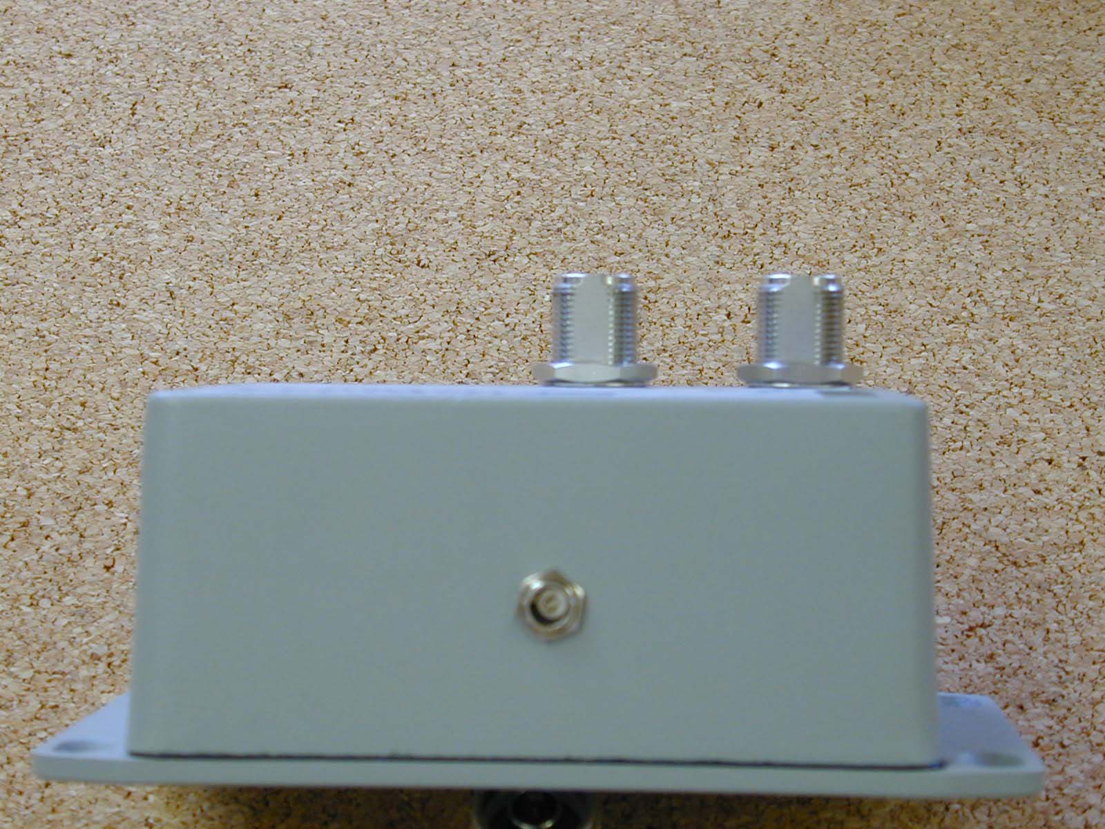
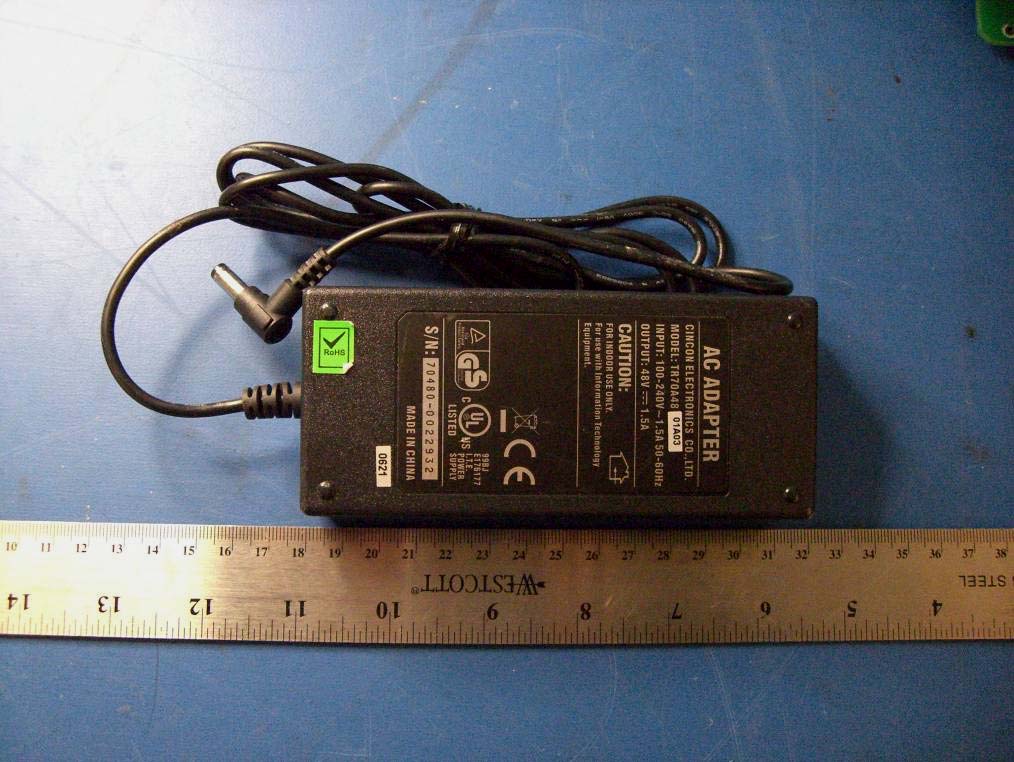
Fidelity Comtech, Inc. FCC ID: Q2AFCI3100X, IC: 4569A-FCI3100X Report No.: R0709271 Page 101 of 117 FCC Part 15.247 and IC RSS-210 15 EXHIBIT C - EUT PHOTOGRAPHS 15.1 EUT - Front View 15.2 EUT - Top View Fidelity Comtech, Inc. FCC ID: Q2AFCI3100X, IC: 4569A-FCI3100X Report No.: R0709271 Page 102 of 117 FCC Part 15.247 and IC RSS-210 15.3 EUT - Bottom View 1 15.4 EUT - Bottom View 2 Fidelity Comtech, Inc. FCC ID: Q2AFCI3100X, IC: 4569A-FCI3100X Report No.: R0709271 Page 113 of 117 FCC Part 15.247 and IC RSS-210 15.25 Power Supply - Front View 15.26 Power Supply - Back View Fidelity Comtech, Inc. FCC ID: Q2AFCI3100X, IC: 4569A-FCI3100X Report No.: R0709271 Page 114 of 117 FCC Part 15.247 and IC RSS-210 15.27 Power Injector - Front View 15.28 Power Injector - Side View 1 Fidelity Comtech, Inc. FCC ID: Q2AFCI3100X, IC: 4569A-FCI3100X Report No.: R0709271 Page 115 of 117 FCC Part 15.247 and IC RSS-210 15.29 Power Injector - Side View 2 15.30 Power Injector - Back View
Fidelity Comtech, Inc. FCC ID: Q2AFCI3100X, IC: 4569A-FCI3100X Report No.: R0709271 Page 95 of 117 FCC Part 15.247 and IC RSS-210 13 EXHIBIT A – FCC & IC EQUIPMENT LABELING REQUIREMENTS 13.1 FCC § 2.925 Identification of equipment (a) Each equipment covered in an application for equipment authorization shall bear a nameplate or label listing the following: (1) FCC Identifier consisting of the two elements in the exact order specified in §2.926. The FCC Identifier shall be preceded by the term FCC ID in capital letters on a single line, and shall be of a type size large enough to be legible without the aid of magnification. Example: FCC ID XXX123. XXX—Grantee Code 123—Equipment Product Code 13.2 FCC ID Labeling Requirements as per FCC § 15.19 (a) In addition to the requirements in part 2 of this chapter, a device subject to certification, or verification shall be labeled as follows: (3) All other devices shall bear the following statement in a conspicuous location on the device: This device complies with part 15 of the FCC Rules. Operation is subject to the following two conditions: (1) This device may not cause harmful interference, and (2) this device must accept any interference received, including interference that may cause undesired operation. (4) Where a device is constructed in two or more sections connected by wires and marketed together, the statement specified above is required to be affixed only to the main control unit. If the EUT is integrated within another device then a label affixed to the host shall also state, “Contains FCC ID:XXXXXX” (5) When the device is so small or for such use that it is not practicable to place the statement specified under paragraph (a) of this section on it, the information required by this paragraph shall be placed in a prominent location in the instruction manual or pamphlet supplied to the user or, alternatively, shall be placed on the container in which the device is marketed. However, the FCC identifier or the unique identifier, as appropriate, must be displayed on the device. IC: XXXXXX-YYYYYYYY Where: • "XXXXXX-YYYYYYYY" is the certification number • "XXXXXX" is the Certificate Holder Number (CHN), made of at most 6 alphanumeric characters (A-Z, 0-9), assigned by Industry Canada; and • "YYYYYYYY" is the Unique Product Number (UPN), made of at most 8 alphanumeric characters (A-Z, 0-9) assigned by the applicant. • Note 1: The term "IC" before the equipment certification number only signifies that the Industry Canada technical specifications were met. • Note 2: Note 1 shall be conspicuously placed in the equipment user manual. • Note 3: Permitted alphanumeric characters used in the CHN and UPN are limited to capital letters (A-Z) and digits (0-9). Other characters, such as "#", "/" or "-", shall not be used. Fidelity Comtech, Inc. FCC ID: Q2AFCI3100X, IC: 4569A-FCI3100X Report No.: R0709271 Page 96 of 117 FCC Part 15.247 and IC RSS-210 13.3 Specifications: As per RSS GEN 5.2 Equipment Labeling: Equipment subject to certification under the applicable RSS, shall be permanently labeled on each item, or as an inseparable combination. The label must contain the following information for full compliance: (a) The certification number, prefixed by the term “IC:”; (b) The manufacturer's name, trade name or brand name; and (c) A model name or number. Equipment for which a certificate has been issued is not considered certified if it is not properly labeled. The information on the Canadian label can be combined with the manufacturer’s other labeling requirements. If the device size is too small to put a label, the label can be included in the user’s manual, upon agreement with Industry Canada. 13.4 Suggested FCC ID & IC Label Fidelity Comtech, Inc. FCC ID: Q2AFCI3100X, IC: 4569A-FCI3100X Report No.: R0709271 Page 97 of 117 FCC Part 15.247 and IC RSS-210 13.5 Suggested Label Location
Fidelity Comtech, Inc. FCC ID: Q2AFCI3100X, IC: 4569A-FCI3100X Report No.: R0709271 Page 103 of 117 FCC Part 15.247 and IC RSS-210 15.5 EUT Cover off - Front View 15.6 EUT Cover off - Top View Fidelity Comtech, Inc. FCC ID: Q2AFCI3100X, IC: 4569A-FCI3100X Report No.: R0709271 Page 104 of 117 FCC Part 15.247 and IC RSS-210 15.7 EUT Side View 1 with Filter Board 15.8 EUT Side View 1 without Filter Board Fidelity Comtech, Inc. FCC ID: Q2AFCI3100X, IC: 4569A-FCI3100X Report No.: R0709271 Page 105 of 117 FCC Part 15.247 and IC RSS-210 15.9 EUT Side View 2 15.10 Antenna off – Top View 1 Fidelity Comtech, Inc. FCC ID: Q2AFCI3100X, IC: 4569A-FCI3100X Report No.: R0709271 Page 106 of 117 FCC Part 15.247 and IC RSS-210 15.11 RF Control Board – Front View 15.12 RF Control Board – Side View Fidelity Comtech, Inc. FCC ID: Q2AFCI3100X, IC: 4569A-FCI3100X Report No.: R0709271 Page 107 of 117 FCC Part 15.247 and IC RSS-210 15.13 RF Control Board – Back View 15.14 Antenna off – Top View 2 Fidelity Comtech, Inc. FCC ID: Q2AFCI3100X, IC: 4569A-FCI3100X Report No.: R0709271 Page 108 of 117 FCC Part 15.247 and IC RSS-210 15.15 Main PCB Board with Radio Components View 15.16 Main PCB Board Solder View Fidelity Comtech, Inc. FCC ID: Q2AFCI3100X, IC: 4569A-FCI3100X Report No.: R0709271 Page 109 of 117 FCC Part 15.247 and IC RSS-210 15.17 Main Radio with Shield on - Front View 15.18 Main Radio with Shield off - Front View Fidelity Comtech, Inc. FCC ID: Q2AFCI3100X, IC: 4569A-FCI3100X Report No.: R0709271 Page 110 of 117 FCC Part 15.247 and IC RSS-210 15.19 Main Radio - Back View 15.20 Sub Radio - Front View Fidelity Comtech, Inc. FCC ID: Q2AFCI3100X, IC: 4569A-FCI3100X Report No.: R0709271 Page 111 of 117 FCC Part 15.247 and IC RSS-210 15.21 Sub Radio - Back View 15.22 Filter with Cover on - Front View Fidelity Comtech, Inc. FCC ID: Q2AFCI3100X, IC: 4569A-FCI3100X Report No.: R0709271 Page 112 of 117 FCC Part 15.247 and IC RSS-210 15.23 Filter with Cover off - Front View 15.24 Filter - Back View
Fidelity Comtech, Inc. FCC ID: Q2AFCI3100X, IC: 4569A-FCI3100X Report No.: R0709271 Page 10 of 117 FCC Part 15.247 and IC RSS-210 4 FCC §15.247 (i) and §2.1091, IC RSS-Gen 5.5 & RSS-102 - RF EXPOSURE 4.1 Applicable Standard According to §15.247 (i) and §1.1307(b)(1), systems operating under the provisions of this section shall be operated in a manner that ensures that the public is not exposed to radio frequency energy level in excess of the Commission’s guidelines. According to §1.1310 and §2.1091 RF exposure is calculated. Limits for General Population/Uncontrolled Exposure Limits for General Population/Uncontrolled Exposure Frequency Range (MHz) Electric Field Strength (V/m) Magnetic Field Strength (A/m) Power Density (mW/cm 2 ) Averaging Time (minutes) 0.3-1.34 614 1.63 *(100) 30 1.34-30 824/f 2.19/f *(180/f 2 ) 30 30-300 27.5 0.073 0.2 30 300-1500 / / f/1500 30 1500-100,000 / / 1.0 30 f = frequency in MHz * = Plane-wave equivalent power density 4.2 MPE Prediction Prediction of MPE limit at a given distance Equation from page 18 of OET Bulletin 65, Edition 97-01 S = PG/4πR² Where: S = power density P = power input to antenna G = power gain of the antenna in the direction of interest relative to an isotropic radiator R = distance to the center of radiation of the antenna 4.3 Test Result The power density level at 35 cm distance is 0.977 mW/cm², which is below the uncontrolled exposure limit of 1.0mW/cm² at 2437 MHz. Maximum peak output power at antenna input terminal (dBm): 26.77 Maximum peak output power at antenna input terminal (mW): 475.34 Prediction distance (cm): 35 Prediction frequency (MHz): 2437 Maximum Antenna Gain, typical (dBi): 15 Maximum Antenna Gain (numeric): 31.62 Power density of prediction frequency at 20.0 cm (mW/cm 2 ): 0.977 MPE limit for uncontrolled exposure at prediction frequency (mW/cm 2 ): 1.0 Fidelity Comtech, Inc. FCC ID: Q2AFCI3100X, IC: 4569A-FCI3100X Report No.: R0709271 Page 11 of 117 FCC Part 15.247 and IC RSS-210 According to RSS-102 Issue 2, November 2005 §2.5.2 exception from Routine Evaluation Limits- RF Exposure Evaluation: RF exposure evaluation is required if the separation distance between the user and the device is greater than 20 cm, except when the device operates: 1) below 1.5 GHz and its e.i.r.p. is equal to or less than 2.5 W; 2) at or above 1.5 GHz and the e.i.r.p. of the device is equal to or less than 5 W. RF limits for device used by the general public is provided hereinafter table: Frequency Range (MHZ) Electric Field (V/M rms) Magnetic Field (A/m rms) Power Density (W/m2) Time Averaging (min) 0.003 – 1 280 2.19 - 6 1 – 10 280 / f 2.19 / f - 6 10 – 30 28 2.19 / f - 6 30 – 300 28 0.073 2* 6 300 - 1500 1.585 f 0.5 0.0042 f 0.5 f / 150 6 1500 – 15 000 61.4 0.163 10 6 15 000 – 150 000 61.4 0.163 10 616000 / f 1.2 150 000 – 300 000 f 0.5 4.21 x 10 -4 f 0.5 6.67 x 10 -5 f 616000 / f 1.2 Note: f is the frequency in MHz * Power density limit applicable at frequency greater than 100 MHz. 4.4 Test Result The power density level at 35 cm distance is 9.77 W/m², which is below the uncontrolled exposure limit of 10W/m² at 2437 MHz.
Note: This test report is for the customer shown above and their specific product only. It may not be duplicated or used in part without prior written consent from Bay Area Compliance Laboratories Corp. This report must not be used by the customer to claim product certification, approval, or endorsement by NVLAP, NIST, or any agency of the Federal Government . FCC PART 15.247 INDUSTRY CANADA RSS-210, ISSUE 7, JUNE 2007 MEASUREMENT AND TEST REPORT For Fidelity Comtech, Inc. 2400 Trade Centre Ave, Longmont, CO 80503, USA FCC ID: Q2AFCI3100X IC ID: 4569A-FCI3100X Model: FCI-3100X Report Type: Original Report Product Type: Phased Array WLAN Terminal Test Engineer(s): Choon-Sian Ooi Report Number: R0709271 Report Date: 2008-01-16 Reviewed By: James Ma, Test Engineer Prepared By: Bay Area Compliance Laboratories Corp. (BACL) 1274 Anvilwood Ave. Sunnyvale, CA 94089, USA Tel: (408) 732-9162 Fax: (408) 732-9164 Fidelity Comtech, Inc. FCC ID: Q2AFCI3100X, IC: 4569A-FCI3100X Report No.: R0709271 Page 2 of 117 FCC Part 15.247 and IC RSS-210 TABLE OF CONTENTS 1 GENERAL INFORMATION .....................................................................................…
Text truncated - open the document above for the full version.
| # | Rule Parts | Frequency Range | Power Output |
|---|---|---|---|
| 2 | 15C | 2.41 GHz - 2.46 GHz | 418.00 mW |

Wireless LAN System with Amplifier
Equipment Class
DTS - Digital Transmission System