FCCID.CO- FCC ID Database
HomeCompaniesEquipment ClassesSearch

© 2026 FCC ID Database. All rights reserved.

AboutContactData sourced from FCC public records
  1. Home/
  2. HIGH-TEK HARNESS ENTERPRISE CO., LTD./
  3. Q2EWLAN01

Q2EWLAN01802.11b mini-PCI Card

HIGH-TEK HARNESS ENTERPRISE CO., LTD.
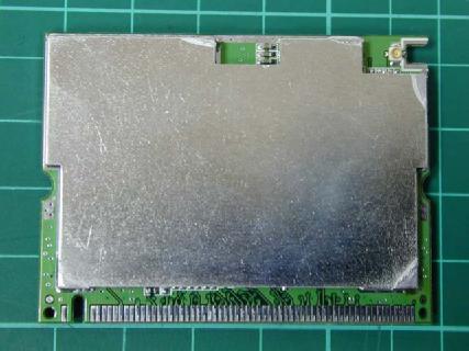
802.11b mini-PCI Card - FCC ID Q2EWLAN01 - HIGH-TEK HARNESS ENTERPRISE CO., LTD.
Click to zoom

Application Details

Equipment Class
DTS - Digital Transmission System
Date of Grant
May 05, 2003
Application Purpose
Original Equipment
Date of Application
May 05, 2003
Equipment Note
802.11b mini-PCI Card
Frequency Range
2412.00000000 - 2462.00000000
Company
HIGH-TEK HARNESS ENTERPRISE CO., LTD.
Country
Taiwan

Documents & Files

Select a file to view

Users Manual

↗

Cover Letter(s)

↗
↗
↗

External Photos

↗

ID Label/Location Info

↗

Internal Photos

↗

RF Exposure Info

↗

Test Report

↗
↗
↗
↗
↗

Test Setup Photos

↗
↗

Document Text

Text extracted from the exhibit documents filed with the FCC. Open a document above to read the original.

Users Manual

1 HTKWLAN01 11Mbps MINIPCI WLAN Card User’s Guide A. Introduction The HTKWLAN01 Wireless Local Area Network(WLAN) MINIPCI Card enables high-speed access without wires to network assets. This WLAN card uses the IEEE 802.11b protocol to enable communications between the host and the other computers, using the 2.4GHz ISM Radio Band for the communications medium. It supports the IEEE 802.11b network specification for Direct Sequence Spread Spectrum (DSSS) signaling, providing data rates of 1, 2, 5.5, 11Mbps. The host computer uses the HTKWLAN01 WLAN card for communications in the same way that it would use an Ethernet adapter. B. Features Support for 11, 5.5, 2 and 1 Megabit Per Second (Mbps) Data Rate Supports the IEEE 802.11 Direct Sequence Specification Driver Supports Microsoft Windows 95, 98, 2000, XP Provides Wireless Data Communication at Full Ethernet Speed Designed to Fully Support Minipci Type 3B Defined Mechanical and Environment Stress Conditions C. Specifications C. 1 General Specifications ??Targeted Standard .............................IEEE 802.11b ??Data Rate.......................................1 Mbps DBPSK 2 Mbps DQPSK 5.5Mbps CCK 11Mbps CCK 2 ??Range............................................Up to 100m, Indoor Up to 300m, Outdoor ??Frequency Range..............................2412~2484MHz ??Step Size.........................................1MHz ??IF Frequency....................................374.25MHz ??IF Bandwidth....................................17MHz ??Rx/Tx Switching Speed.........................2us(Typ.) ??Operating Voltage................................3.0~3.6 V DC ??Operating Temperature Range..................0~70 ??Storage Temperature Range.....................-20 ??Mechanical........................................Type 3B Minipci Card ??Antenna Interface.................................I-pex, 50 C. 2 Receive Specifications ??Sensitivity...........................................-83dbm(Typ.) ??RX Supply Current.................................300mA(Typ.) C. 3 Transmit Specifications ??Output Power........................................+14dbm(Typ.) ??Transmit Spectral Mask.....................-30dBc(Typ.) at First Side-Lobe ??Supply Current.......................................450mA(Typ.) 3 D. Installation Drivers D. 1 Installation of HTKWLAN01 Windows Drivers Step 1. With the HTKWLAN01 MINIPCI WLAN Card insert into the MINIPCI slot where is inside your computer, and then boot your computer under Microsoft Windows 95, 98,2000 or XP. Step 2. Once your computer system has booted and to show a message that detecting a new device, in the same time insert the Disk what is HTKWLAN01’s Driver for Windows into the CD-ROM drive. Step 3. Select “Install from a list or specific location (Advanced)”, and then click “Next” to continue, as shown in the above-mentioned illustration. Step 4. Browse correct path for driver disk, and then click “Next”, as shown in the following illustration. 4 Step 5. Click “Continue Anyway”, as shown in the following illustration. 5 Step 6. Select “High Tek HTK3 Wireless LAN PCI Card”, and then click “Finish”, as shown in the following illustration. The driver installation is completed. D. 2 Operation After you installed HTKWLAN01 driver completely, both the driver and the Configuration Utility are installed on your computer, it’s icon appears in the System Tray in the bottom right corner of your computer. The color and layers are to shine behind the High-Tek(HTK) logo indicates the link status. ??Red and one layer to shine indicating no or very poor link quality. HTKWLAN01 Configuration Utility Icon 6 ??Yellow and two layers to shine indicating a usable but weak link. ??Green and all layers to shine indicating a good or excellent link. ??Clicking on the System Tool Tray Icon displays a menu similar to the following illustration: The first two items in the menu let you turn the wireless radio on or off. When the wireless radio is turned off, the following icon appears in the system tray. D. 3 Starting the Configuration Utility You can launch the Configuration Utility by clicking on the Configuration Utility icon and selecting one of the last four commands in the pop-up menu. The Configuration Utility consists of a window with four tabs: Status, Configuration, Encryption, and About Status Menu: The status menu displays information on the current status of your connection to the WLAN. You can display this menu by choosing the Wireless Network Status... command from the pop-up menu, or by clicking on the Status tab when the Configuration Utility is displayed on your computer. The fields in this menu provide the following information: State: shows the association state of your computer with the wireless LAN. When operating in Infrastructure mode, this field shows the MAC address of the Access Point with which you are communicating. When operating in Peer-to Peer mode, this field shows the virtual MAC address used by computers participating in the AdHoc 7 network. Current T x Rate: shows the current transmit rate of the current association. Current Channel: shows the channel on which the connection is made. In Infrastructure mode, this number changes as the radio scans the available channels. Throughput: shows the short term transmit and receive throughput in bytes/second, and is continuously updated. Link Quality: is based on the quality of the received signal of Access Point beacon. Signal Strength: is based on the received signal strength measurement of the baseband processor of the Beacon signal. You can click the Disable Radio button to turn off the wireless radio. When you click this button, the State field indicates that the radio has been turned off and remaining fields in this window display either a zero or Not Applicable. Click this button again to turn the radio back on. You can click the Rescan button to force the radio to rescan all available channels. If your link quality or signal strength is poor, rescanning can be used to p…

Text truncated - open the document above for the full version.

Cover Letter(s)

May 2, 2003 American Telecommunications Certification Body Inc. 6731 Whittier Ave, McLean, VA 22101 Attn: Mr. William Regarding to your review comments, please see the response listed as below: 1) We have taken the photos as per your requirement. Please find the photos as file name: External photo-1 & Internal photo-1. 2) Please find the revised relative documents (added the company address, phone, fax on the letterhead) as per your requirement. (file name: Confidential letter-1). 3) The client provided the information of responsible party in USA in the user’s manual. Please find the revised manual as one of attachments. (File name: Installation guide-1) 4) We modified the “Modular Approval letter” as per your requirement and submitted to you for your reference. Please find the attached 5) After confirmation with our engineer for the band-edge plot, we are sure the plot has showed both Peak and Average values. Would you explain it more details? 6) The RF power is Peak value. 7) The “worst case” emission is 11Mbps data rates for all emission modes. I hope the attachments satisfy all your requirements for reviewing this application. If you have any questions, please feel free to contact me. Best Regards, Elton Chen Supervisor Intertek Testing Service Taiwan Ltd. E-mail: [email protected]

Cover Letter(s)

FCC ID: Q2EWLAN01 Date: April 16, 2003 Modular Approval Request Letter Dear Sir, There’s a 802.11b MiniPCI WLAN Card -Model that would like to have your authorization as a modular approval. The specific product as below, 802.11b MiniPCI WLAN Card –Model: HTKWLAN01, with its designed features and specified description, meets special requirements for full modular approval on FCC Public Notice DA 00-1407 by cross-reference list below. Company : HIGH-TEK HARNESS ENTERPRISE CO., LTD. Model Name : 802.11b MiniPCI WLAN Card Model Number : HTKWLAN01 FCC ID : Q2EWLAN01 Requirement of Public Notice DA00-1407 Reference to HTKWLAN01 1. The modular transmitter must have its own RF shielding. The module has its own RF shielding. Please see external photo.pdf 2. The modular transmitter must have buffered modulation/data inputs. The modular has buffered data inputs. Please see diagram.pdf 3. The modular transmitter must have its own power supply regulation. All power lines derived from the host device are regulated before energizing other circuits internal to the HTKWLAN01. Please see circuit.pdf 4. The modular transmitter must comply with the antenna requirements of Section 15.203 and 15.204(c). The HTKWLAN01 meets the FCC antenna requirements. Please see external photo.pdf 5. The modular transmitter must be tested in a stand-alone configuration, i.e., the module must not be inside another device during testing. The HTKWLAN01 was tested in a stand-alone configuration via a MiniPCI to PCI interface extender. Please see conducted set-up photo.pdf and spurious set-up photo.pdf 6. The modular transmitter must be labeled with its own FCC ID number, and, if the FCC ID is not visible when the module is installed inside another device, then the outside of the device into which the module is installed must also display a label referring to the enclosed module. The label position of HTKWLAN01 is clearly indicated. Please see the label.pdf 7. The modular transmitter must comply with any specific rule or operating requirements applicable to the transmitter and the manufacturer must provide adequate instructions along with the module to explain any such requirements. A copy of these instructions must be included in the application for equipment authorization. The HTKWLAN01 is compliant with all applicable FCC rules. Detail instructions are given in the Users Manual. Please see Installation guide.pdf 8. The modular transmitter must comply with any applicable RF exposure requirements. For example, FCC Rules in Sections 2.1091, 2.1093 and specific Sections of Part 15, including 15.319(i), 15.407(f), 15.253(f) and 15.255(g), require that Unlicensed PCS, UNII and millimeter wave devices perform routine environmental evaluation for RF Exposure to demonstrate compliance. In addition, spread spectrum transmitters operating under Section 15.247 are required to address RF Exposure compliance in accordance with Section 15.247(b)(4). The HTKWLAN01 comply with applicable RF exposure requirements. Please see RF safety evaluation. pdf Yours sincerely, Elton Chen Supervisor Intertek Testing Service Taiwan Ltd.

External Photos

Photo 1: Outlook photo

ID Label/Location Info

Long: 5.2cm Wide: 2.2cm FCC ID Label Location

Internal Photos

Photo 1: Internal photo

RF Exposure Info

Intertek Testing Services ETL SEMKO FCC ID. : Q2EWLAN01 Report No.: EME-030419 Page 1 of 1 Maximum Permissible Exposure (MPE) Evaluation Report Report No. : EME-030419 Model No. : HTKWLAN01 Issued Date : April 10, 2003 Applicant : HIGH-TEK HARNESS ENTERPRISE CO., LTD. 4F-6, No. 18, Pu-Ting Rd., Hsinchu, Taiwan Test By : Intertek Testing Services Taiwan Ltd. No. 11, Lane 275, Ko-Nan 1 Street, Chia-Tung Li, Shiang-Shan District, Hsinchu City, Taiwan This test report consists of 5 pages in total. It may be duplicated completely for legal use with the allowance of the applicant. It shall not be reproduced except in full, without the written approval of ITS Laboratory. The test result in this report only applies to the tested sample. Jerry Liu Project Engineer Reviewed By Elton Chen Intertek Testing Services ETL SEMKO FCC ID. : Q2EWLAN01 Report No.: EME-030419 Page 2 of 2 Table of Contents Summary of Tests.........................................................................................................3 1. Introduction..............................................................................................................4 2. RF Exposure Limit...................................................................................................4 3. RF Exposure calculations..........................................................................................5 Intertek Testing Services ETL SEMKO FCC ID. : Q2EWLAN01 Report No.: EME-030419 Page 3 of 3 Summary of Tests MPE Evaluation meet FCC OET No. 65: 1997/ IEEE C95.1-1999 802.11b MiniPCI WLAN Card-Model: HTKWLAN01 FCC ID: Q2EWLAN01 Test Reference Results MPE Evaluation FCC Guidelines for Human Exposure IEEE C95.1 Complies Intertek Testing Services ETL SEMKO FCC ID. : Q2EWLAN01 Report No.: EME-030419 Page 4 of 4 1. Introduction The EUT operates in the 2.4GHz ISM band. The EUT (antenna included) is compliant with modular approval and the normal operation distance (after installing in other device, such as router or access point), 20cm from the human body; therefore, the EUT is defined as a Mobile Device. The reason to do the MPE Evaluation is to avoid the RF hazard to human body. The maximum output power and gain of the antenna were used to calculate the limited distance from the product. The limit for Maximum Permissible Exposure (MPE) specified in FCC 1.1310 is followed. The Notice in Installation Manual has been stated as below: While installing and operating this transmitter, the radio frequency exposure limit of 1mW/(cm*cm) may be exceeded at distances close to the transmitter. therefore, the user must maintain a minimum distance of 20 cm from the device at all time. 2. RF Exposure Limit According to FCC 1.1310: The criteria listed in the following table shall be used to evaluate the environmental impact of human exposure to radio-frequency (RF) radiation as specified in 1.1307(b). Limits for Maximum Permissible Exposure (MPE) Frequency Range (MHz) Electric Field Strength (V/m) Magnetic Field Strength (A/m) Power Density (mW/cm 2 ) Average Time (minutes) (A) Limits for Occupational / Control Exposures 30-300 61.4 0.163 1.0 6 300-1500 - - F/300 6 1500-100,000 - - 5 6 (B) Limits for General Population / Uncontrolled Exposure 30-300 27.5 0.073 0.2 30 300-1500 - - F/1500 30 1500-100,000 - - 1.0 30 F= Frequency in MHz Intertek Testing Services ETL SEMKO FCC ID. : Q2EWLAN01 Report No.: EME-030419 Page 5 of 5 3. RF Exposure calculations From § FCC 1.1310 table 1, the maximum permissible RF exposure for an uncontrolled environment is 1mW/(cm*cm), where, (cm*cm) = square cm. The electric field generated for a 1mW/(cm*cm) exposure (S) is calculated as follows: S = E*E/Z where, S = Power density E = Electric field Z = Impedance so, 1mW/(cm*cm) = 10 W/(m*m) Z is 377 ohm of the impedance of free space, where E and H field are perpendicular. Thus the Electric field to produce a 1mW/(cm*cm) exposure is: E = (10 x 377) ½ = 61.4 V/m, which is equivalent to 1mW/(cm*cm) Maximum conducted peak output power is 14.89 dBm and maximum antenna gain is 0 dBi. The maximum radiated output power resulted in 30.83 mW. Using the relationship between electric field E, effective radiated power in watts P, and distance in meters D, the corresponding distance D to produce a 1mW/(cm*cm) is calculated by the following expression: D = (P x 30) ½ /E = (30.83 x 10 x 30) ½ /61.4 = 1.57 cm where, P: maximum effective radiated power measured, 14.89 dBm (30.83 mW) E: electric field equivalent to 1mW/(cm*cm), 61.4 V/m The minimum distance by calculation and normal use distance were listed in the table as below: E.I.R.P. Calculated RF Exposure Allowable Minimum Separation Distance(cm) Normal Use Minimum RF Exposure Separation Distance(cm) dBm mW 14.89 30.83 1.57 20 The calculated Minimum allowable distance is very close to the antenna, and is far away from the normal use distance.

Test Report

Intertek Testing Services ETL SEMKO FCC ID. : Q2EWLAN01 Report No.: EME-030419 Page 1 of 26 EMC TEST REPORT Report No. : EME-030419 Model No. : HTKWLAN01 Issued Date : April 10, 2003 Applicant : HIGH-TEK HARNESS ENTERPRISE CO., LTD. 4F-6, No. 18, Pu-Ting Rd., Hsinchu, Taiwan Test By : Intertek Testing Services Taiwan Ltd. No. 11, Lane 275, Ko-Nan 1 Street, Chia-Tung Li, Shiang-Shan District, Hsinchu City, Taiwan This test report consists of 26 pages in total. It may be duplicated completely for legal use with the allowance of the applicant. It shall not be reproduced except in full, without the written approval of ITS Laboratory. The test result in this report only applies to the tested sample. Jerry Liu Project Engineer Reviewed By Elton Chen Intertek Testing Services ETL SEMKO FCC ID. : Q2EWLAN01 Report No.: EME-030419 Page 2 of 26 Table of Contents Summary of Tests.........................................................................................................3 1. General information..................................................................................................4 1.1 Identification of the EUT....................................................................................4 1.2 Additional information about the EUT................................................................4 1.3 Antenna description............................................................................................5 1.4 Peripherals equipment.........................................................................................5 2. Test specifications.....................................................................................................6 2.1 Test standard.......................................................................................................6 2.2 Operation mode...................................................................................................6 2.3 Test equipment....................................................................................................7 3. Minimum 6dB Bandwidth test..................................................................................8 3.1 Operating environment........................................................................................8 3.2 Test setup & procedure........................................................................................8 3.3 Measured data of Minimum 6dB Bandwidth test results......................................8 4. Maximum Output Power test....................................................................................9 4.1 Operating environment........................................................................................9 4.2 Test setup & procedure........................................................................................9 4.3 Measured data of Maximum Output Power test results........................................9 5. Radiated Emission test............................................................................................10 5.1 Operating environment......................................................................................10 5.2 Test setup & procedure......................................................................................10 5.3 Emission limits.................................................................................................11 5.4 Radiated spurious emission test data.................................................................12 5.4.1 Measurement results: frequencies equal to or less than 1 GHz........................12 5.4.2 Measurement results: frequency above 1GHz.................................................15 6. Power Spectrum Density test..................................................................................21 6.1 Operating environment......................................................................................21 6.2 Test setup & procedure......................................................................................21 6.3 Measured data of Power Spectrum Density test results......................................21 7. Emission on the band edge §FCC 15.247(C)...........................................................22 8. Power Line Conducted Emission test §FCC 15.207................................................23 8.1 Operating environment......................................................................................23 8.2 Test setup & procedure......................................................................................23 8.3 Power Line Conducted Emission test data.........................................................24 Intertek Testing Services ETL SEMKO FCC ID. : Q2EWLAN01 Report No.: EME-030419 Page 3 of 26 Summary of Tests 802.11b MiniPCI WLAN Card-Model: HTKWLAN01 FCC ID: Q2EWLAN01 Test Reference Results Minimum 6dB Bandwidth test 15.247(a)(2) Complies Maximum Output Power test 15.247(b) Complies Radiated Spurious Emission test 15.205, 15.209 Complies Power Spectrum Density test 15.247(d) Complies Power Line Conducted Emission test 15.207 Complies Intertek Testing Services ETL SEMKO FCC ID. : Q2EWLAN01 Report No.: EME-030419 Page 4 of 26 1. General information 1.1 Identification of the EUT Applicant : HIGH-TEK HARNESS ENTERPRISE CO., LTD. Product : 802.11b MiniPCI WLAN Card Model No. : HTKWLAN01 FCC ID. : Q2EWLAN01 Frequency Range : 2412MHz~2462MHz Channel Number : 11 Frequency of Each Channel : 2412MHz, 2417MHz, 2422MHz, 2427MHz, 2432MHz, 2437MHz, 2442MHz, 2447MHz, 2452MHz, 2457MHz, 2462MHz Type of Modulation : CCK (11Mps, 5.5Mbps), DQPSK (2Mbps), DBPSK (1Mbps) Rated Power : DC 3.3V Power Cord : N/A Test Voltage : 3.3Vdc from PC Sample Received : April 1, 2003 Test Date(s) : April 1, 2003 to April 3, 2003 A FCC DoC report has been generated for the client. 1.2 Additional information about the EUT The HTKWLAN01 Wireless Local Area Network (WLAN) MINIPCI Card enables high- speed access without wires to network asset…

Text truncated - open the document above for the full version.

Test Setup Photos

Photo 1: Spurious Test Set-up (front) Photo 2: Spurious Test Set-up (rear)

Test Setup Photos

Photo 1: Spurious Test Set-up (front) Photo 2: Spurious Test Set-up (rear)

Contact Information

Applicant

Ruler Chen(Section Manager)
[email protected]886-3-6663993Fax: 886-3-6663995

Technical Contact

Intertek Testing Services Taiwan Ltd.Elton Chen
[email protected]+886 3 519 1411

No. 11, Lane 275, Ko-Nan 1 Street · Hsinchu City · Taiwan

Test Firm

Intertek Testing Services Taiwan Ltd.Alpha Liu
[email protected]886-3-519-1411Fax: 886-3-519-1410

Technical Specifications

#Rule PartsFrequency RangePower Output
115C2.41 GHz - 2.46 GHz30.80 mW
Modular Type
Single Modular Approval
Confidentiality
Long Term
Grant Notes
Modular Approval. Power Output listed is Conducted. The antenna used for this transmitter must be installed to provide a separation distance of at least 20 cm from all persons and must not be co-located or operating in conjunction with any other antenna or transmitter. End-users and installers must be provided with antenna installation instructions and transmitter operating conditions for satisfying RF exposure compliance.

Other Applications from HIGH-TEK HARNESS ENTERPRISE CO., LTD.
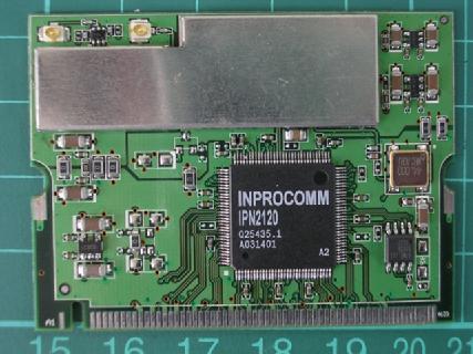
802.11b Mini-PCI Card - FCC ID Q2EWLAN02 - HIGH-TEK HARNESS ENTERPRISE CO., LTD.
Q2EWLAN02

802.11b Mini-PCI Card

Jul 18, 2003

Equipment Class

DTS - Digital Transmission System