Text extracted from the exhibit documents filed with the FCC. Open a document above to read the original.
1 HTKWLAN02 11Mbps MINIPCI WLAN Card User’s Guide A. Introduction The HTKWLAN02 Wireless Local Area Network(WLAN) MINIPCI Card enables high-speed access without wires to network assets. This WLAN card uses the IEEE 802.11b protocol to enable communications between the host and the other computers, using the 2.4GHz ISM Radio Band for the communications medium. It supports the IEEE 802.11b network specification for Direct Sequence Spread Spectrum (DSSS) signaling, providing data rates of 1, 2, 5.5, 11Mbps. The host computer uses the HTKWLAN02 WLAN card for communications in the same way that it would use an Ethernet adapter. B. Features Support for 11, 5.5, 2 and 1 Megabit Per Second (Mbps) Data Rate Supports the IEEE 802.11 Direct Sequence Specification Driver Supports Microsoft Windows 98/SE, Me, 2000, XP Provides Wireless Data Communication at Full Ethernet Speed Designed to Fully Support Minipci Type 3B Defined Mechanical and Environment Stress Conditions C. Specifications C. 1 General Specifications ??Targeted Standard .............................IEEE 802.11b ??Data Rate.......................................1 Mbps DBPSK 2 Mbps DQPSK 5.5Mbps CCK 11Mbps CCK 2 ??Range............................................Up to 100m, Indoor Up to 300m, Outdoor ??Frequency Range..............................2400~2499MHz ??Step Size........................................1MHz ??Rx to Tx Switching Speed....................5us(Typ.) ??Tx to Rx Switching Speed....................10us(Typ.) ??Operating Voltage..............................2.7~3.6 V DC ??Operating Temperature Range...............-40~85 ??Storage Temperature Range..................-65 ??Mechanical......................................Type 3B Minipci Card ??Antenna Interface..............................I-pex, 50 C. 2 Receive Specifications ??Sensitivity.......................................-83dbm(Typ.) ??RX Supply Current..............................280mA(Typ.) C. 3 Transmit Specifications ??Output Power...................................+16dbm(Typ.) ??Transmit Spectral Mask.......................-30dBc(Typ.) at First Side-Lobe ??Supply Current..................................400mA(Typ.) D. Installation Drivers D. 1 Installation of HTKWLAN01 Windows Drivers Step 1. With the HTKWLAN02 MINIPCI WLAN Card insert into the MINIPCI slot where is 3 inside your computer, and then boot your computer under Microsoft Windows 98/SE, Me, 2000 or XP. Step 2. Once your computer system has booted and to show a message that detecting a new device, in the same time insert the Disk what is HTKWLAN02’s Driver for Windows into the CD-ROM drive. Step 3. Press “Next” to continue the install shield 4 Step 4. Press “Yes” to continue installing Step 5. Press “Browse” to choose the destination that you require to install, then press “Next” 5 Step 6. Choose “Next” Step 7. Install Shield is installing the program. 6 Step 8. Press “Finish” to complete the installing D. 2 Operation After you installed HTKWLAN02 driver completely, both the driver and the Configuration Utility are installed on your computer, it’s icon appears in the System Tray in the bottom right corner of your computer. 7 The color and layers are to shine behind the High-Tek(HTK) logo indicates the link status. ??Red and one layer to shine indicating no or very poor link quality. ??Yellow and two layers to shine indicating a usable but weak link. ??Green and all layers to shine indicating a good or excellent link. D. 3 Using the Wireless LAN Configuration Utility The Wireless LAN Configuration Utility appears as an icon on the system tray of Windows while the card is running. You can open it by clicking on the icon. While the station is in infrastructure mode and not associated to an Access Point, the color of the icon is red. As soon as the station associates to an Access Point, the icon color automatically turns to “Green”. In Ad-Hoc mode the color is always Green, except when the card is resetting and initializing where it turns to “Purple” during the reset and initialization procedure. The Wireless LAN Configuration Utility is a highly integrated application include the following options (tabs), ??General ??Statistics ??Site Survey ??Encryption ??Advanced ??About General : A typical screen of the application in Infrastructure mode is shown in Figure 1-1. The configuration parameters are shown at the top of the screen. HTKWLAN02 Configuration Utility Icon 8 The fields in this menu provide the following information: The HTK WLAN Interface adapter can operate in one of two types of networks, which are specified in the Network Type: field of the Configuration menu. Clicking the down arrow at the right of this field displays the available types. 1. AdHoc: IEEE 802.11, the standard on which the WLAN protocol is based, defines two modes to handle two separate needs. The first, called AdHoc (or IBSS) mode, is used when two or more wirelessly-enabled PCs wish to exchange data directly, without an Access Point. In this case the PCs can establish a peer-to-peer network in which they are the only members and over which they can exchange data. To exchange data, each computer participating in the AdHoc network must also specify the same 2. Infrastructure: The second mode defined by the IEEE 802.11 standard is called infrastructure mode, and is the primary application for WLAN operation. In this mode all data on the wireless network is directed to an Access Point, which then routes the data to the appropriate wireless station. The Access Point may also be configured to allow data to be bridged from the wireless network to wired networks. To participate in a wireless LAN in infrastructure mode, every station and Access Point must specify the same Network Name. In infrastructure mode, all available channels are scanned for 9 traffic, so there is no need to specify a channel. SSID: Officially, in wireless networks the network name is known as the SSID (Service Set ID entifier), and is used by Access Points and sta…
Text truncated - open the document above for the full version.
FCC ID: Q2EWLAN02 Date: July 8, 2003 Modular Approval Request Letter Dear Sir, There’s a 802.11b Mini PCI WLAN Card that would like to have your authorization as a modular approval. The specific product as below, 802.11b Mini PCI WLAN Card, with its designed features and specified description, meets special requirements for full modular approval on FCC Public Notice DA 00-1407 by cross-reference list below. Company : HIGH-TEK HARNESS ENTERPRISE CO., LTD. Model Name : 802.11b Mini PCI WLAN Card-Model Model Number : HTKWLAN02 FCC ID : Q2EWLAN02 Requirement of Public Notice DA00-1407 Reference to HTKWLAN02 1. The modular transmitter must have its own RF shielding. The module has its own RF shielding. Please see external photo.pdf 2. The modular transmitter must have buffered modulation/data inputs. The modular has buffered data inputs in chip IPN2120. Please see diagram.pdf 3. The modular transmitter must have its own power supply regulation. All power lines derived from the host device are regulated before energizing other circuits internal to the HTKWLAN02 . Please see circuit.pdf 4. The modular transmitter must comply with the antenna requirements of Section 15.203 and 15.204(c). The HTKWLAN02 meets the FCC antenna requirements. Please see external photo.pdf 5. The modular transmitter must be tested in a stand-alone configuration, i.e., the module must not be inside another device during testing. The HTKWLAN02 was tested in a stand-alone configuration. Please see conducted set- up photo.pdf and spurious set-up photo.pdf 6. The modular transmitter must be labeled with its own FCC ID number, and, if the FCC ID is not visible when the module is installed inside another device, then the outside of the device into which the module is installed must also display a label referring to the enclosed module. The label position of HTKWLAN02 is clearly indicated. Please see the label.pdf 7. The modular transmitter must comply with any specific rule or operating requirements applicable to the transmitter and the manufacturer must provide adequate instructions along with the module to explain any such requirements. A copy of these instructions must be included in the application for equipment authorization. The HTKWLAN02 is compliant with all applicable FCC rules. Detail instructions are given in the Users Manual. Please see Installation guide.pdf 8. The modular transmitter must comply with any applicable RF exposure requirements. For example, FCC Rules in Sections 2.1091, 2.1093 and specific Sections of Part 15, including 15.319(i), 15.407(f), 15.253(f) and 15.255(g), require that Unlicensed PCS, UNII and millimeter wave devices perform routine environmental evaluation for RF Exposure to demonstrate compliance. In addition, spread spectrum transmitters operating under Section 15.247 are required to address RF Exposure compliance in accordance with Section 15.247(b)(4). The HTKWLAN02 comply with applicable RF exposure requirements. Please see RF safety evaluation. pdf Yours sincerely, Elton Chen Assistant Manager Intertek Testing Service Taiwan Ltd.
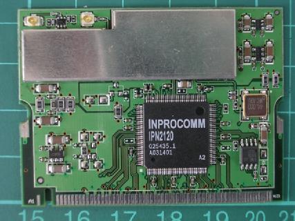
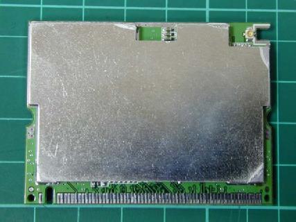
Photo 1: Exterior photo of EUT HTKWLAN02 HTKWLAN02 Photo 2: Antenna photo
: 5.2cm width: 2.2cm
Photo 1: Interior photo of EUT HTKWLAN02 HTKWLAN02
Intertek Testing Services ETL SEMKO FCC ID. : Q2EWLAN02 Report No.: EME-030766 Page 1 of 5 Maximum Permissible Exposure (MPE) Evaluation Report Report No. : EME-030766 Model No. : HTKWLAN02 Issued Date : July 4, 2003 Applicant : HIGH-TEK HARNESS ENTERPRISE CO., LTD. 4F-6, No. 18, Pu-Ting Rd., Hsinchu, Taiwan Test By : Intertek Testing Services Taiwan Ltd. No. 11, Lane 275, Ko-Nan 1 Street, Chia-Tung Li, Shiang-Shan District, Hsinchu City, Taiwan This test report consists of 5 pages in total. It may be duplicated completely for legal use with the allowance of the applicant. It shall not be reproduced except in full, without the written approval of ITS Laboratory. The test result in this report only applies to the tested sample. Jerry Liu Project Engineer Reviewed By Elton Chen Intertek Testing Services ETL SEMKO FCC ID. : Q2EWLAN02 Report No.: EME-030766 Page 2 of 5 Table of Contents Summary of Tests.........................................................................................................3 1. Introduction..............................................................................................................4 2. RF Exposure Limit...................................................................................................4 3. RF Exposure calculations..........................................................................................5 4. Test results................................................................................................................5 Intertek Testing Services ETL SEMKO FCC ID. : Q2EWLAN02 Report No.: EME-030766 Page 3 of 5 Summary of Tests MPE Evaluation meet FCC OET No. 65: 1997/ IEEE C95.1-1999 802.11b Mini PCI WLAN Card-Model: HTKWLAN02 FCC ID: Q2EWLAN02 Test Reference Results MPE Evaluation FCC Guidelines for Human Exposure IEEE C95.1 Complies Intertek Testing Services ETL SEMKO FCC ID. : Q2EWLAN02 Report No.: EME-030766 Page 4 of 5 1. Introduction The EUT operates in the 2.4GHz ISM band. The EUT (antenna included) is compliant with modular approval and the normal operation distance (after installing in other device, such as router or access point), 20cm from the human body; therefore, the EUT is defined as a Mobile Device. The reason to do the MPE Evaluation is to avoid the RF hazard to human body. The maximum output power and gain of the antenna were used to calculate the limited Power density (S) at 20cm distance away from the product. The limit for Maximum Permissible Exposure (MPE) specified in FCC 1.1310 is followed. 2. RF Exposure Limit According to FCC 1.1310: The criteria listed in the following table shall be used to evaluate the environmental impact of human exposure to radio-frequency (RF) radiation as specified in 1.1307(b). Limits for Maximum Permissible Exposure (MPE) Frequency Range (MHz) Electric Field Strength (V/m) Magnetic Field Strength (A/m) Power Density (mW/cm 2 ) Average Time (minutes) (A) Limits for Occupational / Control Exposures 30-300 61.4 0.163 1.0 6 300-1500 - - F/300 6 1500-100,000 - - 5 6 (B) Limits for General Population / Uncontrolled Exposure 30-300 27.5 0.073 0.2 30 300-1500 - - F/1500 30 1500-100,000 - - 1.0 30 F= Frequency in MHz Intertek Testing Services ETL SEMKO FCC ID. : Q2EWLAN02 Report No.: EME-030766 Page 5 of 5 3. RF Exposure calculations From § FCC 1.1310 table 1, the maximum permissible RF exposure for an uncontrolled environment is 1mW/(cm 2 ) Power density (S) is calculated by the following formula: S = (P * G)/4πR 2 where, S = Power density (mW/cm 2 ) P = Output power to antenna (mW) R = Distance between radiating structure and observation point (cm) G = Gain of antenna in numeric π = 3.1416 Example: Assume a mobile device operates at 2412MHz and its maximum output power is 50mW, and the maximum gain of antenna is 1 (numeric) /0dBi. then the power density (S) = (50 * 1)/4* π *20 2 = 0.00995 (mW/cm 2 ) 4. Test results Channel Channel Frequency (MHz) Maximum antenna gain (numeric) Output power to antenna (mW) Power density (mW/cm 2 ) Limit of power density (mW/cm 2 ) 1 2412 1 51.761 0.010298 1.0 6 2437 1 48.417 0.009632 1.0 11 2462 1 47.315 0.009413 1.0 The Notice in Installation Manual has been stated as below: While installing and operating this transmitter, the radio frequency exposure limit of 1mW/(cm*cm) may be exceeded at distances close to the transmitter. therefore, the user must maintain a minimum distance of 20 cm from the device at all time.
Power Output 1. Test Condition & Setup A: B: 1. The output of the transmitter via a 10dB attenuator and coupled to a diode detector. 2. The output of the diode detector connected to the vertical channel of an oscilloscope. The observed trace of the oscilloscope shall be recorded as “A”. 3. The transmitter replaced by a signal generator. The output frequency of the signal made equal to the center of the frequency range occupied by the transmitter and unmodulated. 4. The output of the signal generator raised to reach the peak of trace “A” named X. 5. The signal generator output level X(dBm) is the transmitter output peak power. Recording the following. CH1: 17.14dBm CH6: 16.85dBm CH11: 16.75dBm EUT 10dB ATT Diode detector Oscilloscope S/G 10dB ATT Diode detector Oscilloscope
Intertek Testing Services ETL SEMKO FCC ID. : Q2EWLAN02 Report No.: EME-030766 Page 1 of 31 EMC TEST REPORT Report No. : EME-030766 Model No. : HTKWLAN02 Issued Date : July 4, 2003 Applicant : HIGH-TEK HARNESS ENTERPRISE CO., LTD. 4F-6, No. 18, Pu-Ting Rd., Hsinchu, Taiwan Test By : Intertek Testing Services Taiwan Ltd. No. 11, Lane 275, Ko-Nan 1 Street, Chia-Tung Li, Shiang-Shan District, Hsinchu City, Taiwan This test report consists of 31 pages in total. It may be duplicated completely for legal use with the allowance of the applicant. It shall not be reproduced except in full, without the written approval of ITS Laboratory. The test result in this report only applies to the tested sample. Jerry Liu Project Engineer Reviewed By Elton Chen Intertek Testing Services ETL SEMKO FCC ID. : Q2EWLAN02 Report No.: EME-030766 Page 2 of 31 Table of Contents Summary of Tests.........................................................................................................3 1. General information..................................................................................................4 1.1 Identification of the EUT....................................................................................4 1.2 Additional information about the EUT................................................................4 1.3 Antenna description............................................................................................5 1.4 Peripherals equipment.........................................................................................5 2. Test specifications.....................................................................................................6 2.1 Test standard.......................................................................................................6 2.2 Operation mode...................................................................................................6 2.3 Test equipment....................................................................................................7 3. Minimum 6dB Bandwidth test..................................................................................8 3.1 Operating environment........................................................................................8 3.2 Test setup & procedure........................................................................................8 3.3 Measured data of Minimum 6dB Bandwidth test results......................................8 4. Maximum Output Power test....................................................................................9 4.1 Operating environment........................................................................................9 4.2 Test setup & procedure........................................................................................9 4.3 Measured data of Maximum Output Power test results........................................9 5. Radiated Emission test............................................................................................10 5.1 Operating environment......................................................................................10 5.2 Test setup & procedure......................................................................................10 5.3 Emission limits.................................................................................................11 5.4 Radiated spurious emission test data.................................................................12 5.4.1 Measurement results: frequencies equal to or less than 1 GHz........................12 5.4.2 Measurement results: frequency above 1GHz.................................................15 6. Power Spectrum Density test..................................................................................25 6.1 Operating environment......................................................................................25 6.2 Test setup & procedure......................................................................................25 6.3 Measured data of Power Spectrum Density test results......................................25 7. Emission on the band edge §FCC 15.247(C)...........................................................26 8. Power Line Conducted Emission test §FCC 15.207................................................27 8.1 Operating environment......................................................................................27 8.2 Test setup & procedure......................................................................................27 8.3 Power Line Conducted Emission test data.........................................................29 Intertek Testing Services ETL SEMKO FCC ID. : Q2EWLAN02 Report No.: EME-030766 Page 3 of 31 Summary of Tests 802.11b Mini PCI WLAN Card-Model: HTKWLAN02 FCC ID: Q2EWLAN02 Test Reference Results Minimum 6dB Bandwidth test 15.247(a)(2) Complies Maximum Output Power test 15.247(b) Complies Radiated Spurious Emission test 15.205, 15.209 Complies Power Spectrum Density test 15.247(d) Complies Power Line Conducted Emission test 15.207 Complies Intertek Testing Services ETL SEMKO FCC ID. : Q2EWLAN02 Report No.: EME-030766 Page 4 of 31 1. General information 1.1 Identification of the EUT Applicant : HIGH-TEK HARNESS ENTERPRISE CO., LTD. Product : 802.11b Mini PCI WLAN Card Model No. : HTKWLAN02 FCC ID. : Q2EWLAN02 Frequency Range : 2412MHz to 2462MHz Channel Number : 11 Frequency of Each Channel : 2412MHz, 2417MHz, 2422MHz, 2427MHz, 2432MHz, 2437MHz, 2442MHz, 2447MHz, 2452MHz, 2457MHz, 2462MHz Type of Modulation : CCK (11Mps, 5.5Mbps), DQPSK (2Mbps), DBPSK (1Mbps) Rated Power : DC 3.3V Power Cord : N/A Sample Received : April 23, 2003 Test Date(s) : April 23, 2003 to June 30, 2003 A FCC DoC report has been generated for the client. 1.2 Additional information about the EUT This WLAN card uses the IEEE 802.11b protocol to enable communications between the host and the other computers, using the 2.4GHz ISM Radio Band…
Text truncated - open the document above for the full version.
Photo 1: Conducted Test Set-up (front) HTKWLAN02 Photo 2: Conducted Test Set-up (rear)
Photo 1: Spurious Test Set-up (front) HTKWLAN02 Photo 2: Spurious Test Set-up (rear) HTKWLAN02
No. 11, Lane 275, Ko-Nan 1 Street · Hsinchu City · Taiwan
| # | Rule Parts | Frequency Range | Power Output |
|---|---|---|---|
| 1 | 15C | 2.41 GHz - 2.46 GHz | 52.00 mW |

802.11b mini-PCI Card
Equipment Class
DTS - Digital Transmission System