Q2GIX104-115Tablet PC with WLAN card (PCMCIA)
Xplore Technologies Corp.
Click to zoom
Application Details
- Equipment Class
- DTS - Digital Transmission System
- Date of Grant
- Oct 30, 2003
- Application Purpose
- Original Equipment
- Date of Application
- Oct 30, 2003
- Equipment Note
- Tablet PC with WLAN card (PCMCIA)
- Frequency Range
- 2412.00000000 - 2462.00000000
- Company
- Xplore Technologies Corp.
- Country
- United States
Documents & Files
Document Text
Text extracted from the exhibit documents filed with the FCC. Open a document above to read the original.
Users Manual
ix104USER’S HANDBOOK iX104 USER'S HANDBOOK 4 iX104 User’s Handbook Xplore Technologies ® has made every effort to ensure the accuracy and completeness of this document; however, because ongoing development efforts are made to continually improve the capabilities of our products, we cannot guarantee the accuracy of the contents of this document. We disclaim liability for errors, omissions, or future changes herein. Xplore and the Xplore logo are registered trademarks of Xplore Technologies Corp.; iX104 is a trademark of Xplore Technologies Corp. Kensington and MicroSaver are registered trademarks of the Kensington Technology Group. Microsoft is a registered trademark of Microsoft Corporation. Windows 2000 Professional, Windows XP Professional, and Windows XP Tablet PC Edition are trademarks of Microsoft Corporation. PCMCIA and CardBus are registered trademarks of the Personal Computer Memory Card International Association. Intel, Pentium, and SpeedStep are registered trademarks of Intel Corporation. Wi-Fi is a trademark of the Wireless Ethernet Compatibility Alliance (WECA). FireWire is a registered trademark of Apple Computer, Inc. ISODAMP is a registered trademark of Aearo Company. All other brands, product names, company names, trademarks and service marks used herein are property of their respective companies. Copyright © 2003 Xplore Technologies Corp. All rights reserved. No part of this publication may be copied, reproduced, or translated, without the prior written consent of Xplore Technologies. No part of this publication may be stored or transmitted in any electronic form without the prior consent of Xplore Technologies. Any unauthorized use is a violation of copyright laws. PN: 95-01016 Edition: Second, July 2003 DECLARATION OF CONFORMITY according to FCC Part 15 Responsible Party Name: Xplore Technologies Corp. Address: 14000 Summit Drive, Suite 900, Austin, Texas 78728 Telephone: 512.336.7797 Declares that product: Model Series: iX104 Complies with Part 15 of the FCC Rules iX104 User’s Handbook 5 This device complies with Part 15 of the FCC rules. Operation is subject to the following two conditions: (1) This device may not cause harmful interference, and, (2) This device must accept any interference received, including interference that may cause undesired operation. WARNING Changes or modifications to this unit not expressly approved by the party responsible for compliance may void the user’s authority to operate this equipment. For more information about FCC rules and their applicability to the iX104, see Appendix E, “Agency Notices.” Warranty Information The iX104 and iX104-TPC are backed by a standard 12-month International Limited Warranty. An extended International Limited Warranty is available. Check the service kit included with your computer for warranty terms and conditions. a 6 iX104 User’s Handbook Important safety information Before you use the iX104 or the iX104 dock, read these safety instructions and the operation instructions in this handbook. Failure to observe all these instructions voids the Limited Warranty and may lead to suspension or denial of services to the offender, or legal action, or both. Follow any special regulations governing the use of the computer and, if radio-enabled, always switch it off in areas where radio devices are forbidden or when the radio device can cause interference or danger. Always follow any safety laws and regulations pertaining to the use of cell phones and two-way radios, because these laws and regulations typically apply to the use of the wireless-enabled iX104. Observe all restrictions on the use of radio equipment in fuel depots (fuel storage and distribution areas), chemical plants, and wherever blasting operations are in progress or in any area in which restrictions on radio transmissions are imposed. Switch off the iX104 when in an aircraft. The iX104 is not FAA-approved for use on aircraft. The effect of the use of the iX104 in aircraft is unknown. Using the iX104 in an aircraft may affect aircraft instrumentation, communication, and performance; may disrupt the network; and may be illegal. Operating the wireless-enabled iX104 may interfere with the functioning of inadequately protected medical devices such as pacemakers. Consult a physician or the manufacturer of the medical device if you have any questions. Radio signals from your iX104 will not affect the operation of most modern equipment, but certain electronic equipment, including automotive systems, may not be shielded against radio signals from your iX104. Check with the manufacturer of your motor vehicle or the manufacturer’s representative to determine whether using the iX104 will present any safety issues. Avoid using the iX104 in any environment that requires your full attention, such as when driving a vehicle. If you need to use your iX104 while driving, have a passenger use it for you or find a safe location to halt your vehicle. iX104 User’s Handbook 7 WARNING Use only battery types specified in this handbook. Using any other type of battery can be dangerous and can disable the iX104. WARNING Do not use any dock or any other accessory or attachment that is not manufactured or supplied by Xplore or an authorized Xplore accessories supplier. Use of any accessory or attachment that is not supplied or approved for use with the iX104 by Xplore is not permitted because it may cause hazards. Operate the iX104 only from the type of power source indicated on the marking label. (See page 53 for more information about the battery and power supply.) Route power supply cords so that they are not likely to be walked on or pinched by items placed upon or against them. Pay particular attention to cords at plugs and convenience receptacles, and at the point where cords exit from the computer or its dock. Do not overload wall outlets, extension cords, or integral convenience receptacles because this can cause fire or electric shock. Unplug the iX104 and refer the iX10…
Text truncated - open the document above for the full version.
Cover Letter(s)
Xplore Technologies, Inc. 14000 Summit Road Suite 900 Austin, TX 78728 888-44-XPLORE Page 1 of 1 10/6/2003 October 1, 2003 Federal Communication Commission Equipment Approval Service Attention: Authorization and Evaluation Division Reference: Xplore Technologies FCC ID: Q2GIX104-115 To Whom It May Concern: Subject: Request for Confidentiality Pursuant to Sections 0.457 (d)(1)(ii) and 0.459 of the Commission’s rules, the Applicant hereby requests confidential treatment of the Xplore Technologies supplied information accompanying this application. The confidential information includes the following: • Schematics • Block Diagrams • Bill of Materials • Operational Description The materials contain trade secrets and proprietary information not customarily released to the public. Public disclosure of this information might be harmful to Xplore Technologies and provide unjustified benefits to our competitiors. Xplore Technologies understands that pursuant to 0.457 (d)(1)(ii), disclosure of the Application and all accompanying documentation will not be made before the date of the grant. Best regards, Douglas L. Fowler Sr. Project Engineer Xplore Technologies, Inc.
External Photos
iX104: Exterior - F ront iX104: Exterior - B ack FCC Label iX104: Exterior – B attery Pack Removed iX104: Antenna Locations Wide A r ea Network AntennaLocal Area NetworkAntenna iX104: I/O PCB
External Photos
S24-DS – Top view S24-DS – Bottom view S24-DS – Profile view
ID Label/Location Info
0.125 1.250 4X R 0.025 NOTES: 1. Material: Polycarbonate T= 0.127mm with matted texture 2. Material must be approved by UL, CSA 3. Adhesive Spec Refer to ES-811-RO5 Sony 303 or Toyo Df2700MR or Equiv 4. Print Color: Letters Silver ACD M808 Background Black ACD-M8010 and cool gray 11 5. Print Tolerance of dimensions +0.3/.03 LABEL, IX104, WIRELESS, S24-DS 50-23043 A Xplore Technologies SCALE:2:1 SIZEDWG. NO. A REV. MATERIAL FINISH -- -- DO NOT SCALE DRAWINGAPPLICATION USED ONNEXT ASSY DIMENSIONS ARE IN INCHES TOLERANCES: FRACTIONAL ANGULAR: MACH BEND TWO PLACE DECIMAL THREE PLACE DECIMAL NAME DATE DRAWN CHECKED ENG APPR. MFG APPR. Q.A. SHEET 1 OF 1WEIGHT: COMMENTS: REVISIONS DESCRIPTION REV. DATEAPPROVED THE INFORMATION CONTAINED IN THIS DRAWING IS THE SOLE PROPERTY OF XPLORE TECHNOLOGIES. ANY REPRODUCTION IN PART OR AS A WHOLE WITHOUT THE WRITTEN PERMISSION OF XPLORE TECHNOLOGIES IS PROHIBITED. PROPRIETARY AND CONFIDENTIAL ZONE
Internal Photos
iX104: Antenna Cavities WAN Antenna LAN Antenna iX104: Interior View PCMCIASlot Mini-PCISlot S24-DS iX104: Main Logic Board iX104: Keypad PCB iX104: I/O PCB iX104: I/O PCB Removed
Internal Photos
Network Systems Organization FCC Certification Report for the LA4121 WLAN PC Card FCC ID: H9PLA4121 EXHIBIT 9 INTERNAL PHOTOS H9PLA4121 H9PLA4121 H9PLA4121 H9PLA4121 H9PLA4121 H9PLA4121
RF Exposure Info
SAR Test Report No.: SAR_544_2003_FCC_2450_S24-DS Date of Report: 10/07/2003 Appendix A Plots Page 1 of 4 Date / Time: 9/4/2003 4:02:31 PM Position: lap Filename: *.txt Phantom: HeadBox_new_spout.csv Device Tested: Xplore iX104 802.11b S24-DS Head Rotation: 0 Antenna: integral Test Frequency: 2437 Shape File: xplor802lap.csv Power Level: maximum Probe: 0106 Cal File: 106_2450_BODY_802_11 X Y Z Air 415 805 371 DCP 19 19 19 Cal Factors: Lin 0.58 5 0.58 5 0.58 5 Amp Gain: 2 Averaging: 6 Batteries Replaced: 09/03/2003 Liquid: 2400 Type: Body Conductivity: 1.945 Relative Permittivity: 51.5 Liquid Temp (deg C): 22.0 Ambient Temp (deg C): 22.0 Ambient RH (%): 50 Density (kg/m3): 1000 Software Version: 0.420 ZOOM SCAN RESULTS: Start Scan End Scan Spot SAR (W/kg): 0.006 0.006 Change during Scan (%) 1.45 Max E-field (V/m): 3.61 1g 10g Max SAR (W/kg) 0.021 0.012 X Y Z Location of Max (mm): 75.1 -38.0 -172.0 AREA SCAN: Min Max Steps Y 50.0 -50.0 10.0 Scan Extent: Z -190.0 -100.0 10.0 SAR Test Report No.: SAR_544_2003_FCC_2450_S24-DS Date of Report: 10/07/2003 Appendix A Plots Page 2 of 4 Date / Time: 9/4/2003 4:27:33 PM Position: bystander 1.5cm Filename: *.txt Phantom: HeadBox_new_spout.csv Device Tested: Xplore iX104 802.11b S24-DS Head Rotation: 0 Antenna: integral Test Frequency: 2437 Shape File: xplor802bystand1.csv Power Level: maximum Probe: 0106 Cal File: 106_2450_BODY_802_11 X Y Z Air 415 805 371 DCP 19 19 19 Cal Factors: Lin 0.58 5 0.58 5 0.58 5 Amp Gain: 2 Averaging: 6 Batteries Replaced: 09/03/2003 Liquid: 2400 Type: Body Conductivity: 1.945 Relative Permittivity: 51.5 Liquid Temp (deg C): 22.0 Ambient Temp (deg C): 22.0 Ambient RH (%): 50 Density (kg/m3): 1000 Software Version: 0.420 ZOOM SCAN RESULTS: Start Scan End Scan Spot SAR (W/kg): 0.009 0.009 Change during Scan (%) 3.24 Max E-field (V/m): 4.37 1g 10g Max SAR (W/kg) 0.031 0.019 X Y Z Location of Max (mm): 75.1 25.0 -148.8 AREA SCAN: Min Max Steps Y 50.0 -50.0 10.0 Scan Extent: Z -190.0 -100.0 10.0 SAR Test Report No.: SAR_544_2003_FCC_2450_S24-DS Date of Report: 10/07/2003 Appendix A Plots Page 3 of 4 Date / Time: 9/4/2003 4:58:42 PM Position: bystander 1.5cm Filename: *.txt Phantom: HeadBox_new_spout.csv Device Tested: Xplore iX104 802.11b S24-DS Head Rotation: 0 Antenna: integral Test Frequency: 2412 Shape File: xplor802bystand1.csv Power Level: maximum Probe: 0106 Cal File: 106_2450_BODY_802_11 X Y Z Air 415 805 371 DCP 19 19 19 Cal Factors: Lin 0.58 5 0.58 5 0.58 5 Amp Gain: 2 Averaging: 6 Batteries Replaced: 09/03/2003 Liquid: 2400 Type: Body Conductivity: 1.932 Relative Permittivity: 51.6 Liquid Temp (deg C): 22.0 Ambient Temp (deg C): 22.0 Ambient RH (%): 50 Density (kg/m3): 1000 Software Version: 0.420 ZOOM SCAN RESULTS: Start Scan End Scan Spot SAR (W/kg): 0.010 0.010 Change during Scan (%) -0.12 Max E-field (V/m): 4.18 1g 10g Max SAR (W/kg) 0.029 0.017 X Y Z Location of Max (mm): 75.1 16.0 -147.7 AREA SCAN: Min Max Steps Y 50.0 -50.0 10.0 Scan Extent: Z -190.0 -100.0 10.0 SAR Test Report No.: SAR_544_2003_FCC_2450_S24-DS Date of Report: 10/07/2003 Appendix A Plots Page 4 of 4 Date / Time: 9/4/2003 5:24:31 PM Position: bystander 1.5cm Filename: bystander11_3d.txt Phantom: HeadBox_new_spout.csv Device Tested: Xplore iX104 802.11b S24-DS Head Rotation: 0 Antenna: integral Test Frequency: 2462 Shape File: xplor802bystand1.csv Power Level: maximum Probe: 0106 Cal File: 106_2450_BODY_802_11 X Y Z Air 415 805 371 DCP 19 19 19 Cal Factors: Lin 0.58 5 0.58 5 0.58 5 Amp Gain: 2 Averaging: 6 Batteries Replaced: 09/03/2003 Liquid: 2400 Type: Body Conductivity: 1.961 Relative Permittivity: 51.1 Liquid Temp (deg C): 22.0 Ambient Temp (deg C): 22.0 Ambient RH (%): 50 Density (kg/m3): 1000 Software Version: 0.420 ZOOM SCAN RESULTS: Start Scan End Scan Spot SAR (W/kg): 0.009 0.009 Change during Scan (%) -0.12 Max E-field (V/m): 4.34 1g 10g Max SAR (W/kg) 0.032 0.019 X Y Z Location of Max (mm): 75.0 13.0 -149.3 AREA SCAN: Min Max Steps Y 50.0 -50.0 10.0 Scan Extent: Z -190.0 -100.0 10.0
RF Exposure Info
SAR Test Report No.: SAR_544_2003_FCC_2450_S24-DS Date of Report10/07/2003 Appendix B Page 1 of 1 Appendix B: Photos EUT Photos: Photo 1. Antenna locations SAR Test Report No.: SAR_544_2003_FCC_2450_S24-DS Date of Report10/07/2003 Appendix B Page 2 of 2 Photo 2. EUT front SAR Test Report No.: SAR_544_2003_FCC_2450_S24-DS Date of Report10/07/2003 Appendix B Page 3 of 3 Photo 3. EUT back SAR Test Report No.: SAR_544_2003_FCC_2450_S24-DS Date of Report10/07/2003 Appendix B Page 4 of 4 Setup Photos Photo 4. 2450 MHz antenna bystander position SAR Test Report No.: SAR_544_2003_FCC_2450_S24-DS Date of Report10/07/2003 Appendix B Page 5 of 5 Photo 5. bystander position distance SAR Test Report No.: SAR_544_2003_FCC_2450_S24-DS Date of Report10/07/2003 Appendix B Page 6 of 6 Photo 6. 2450 MHz antenna lap position SAR Test Report No.: SAR_544_2003_FCC_2450_S24-DS Date of Report10/07/2003 Appendix B Page 7 of 7 Photo 7. Photo to demonstrate 15 cm Z-axis flat phantom
RF Exposure Info
SAR Test Report No. SAR_544_2003_FCC_2450_S24-DS Date of Report: 10/07/2003 Appendix C Misc. Page 1 of 38 1 Tissue Parameters 2450MHz Head liquid: Recipe: 53.74% distilled water 22.59% DGBE 22.59% triton X-100 0.98% salt 0.1% bactericide Di-electric constants measured on 9/04/2003. SAR measurements were made within 24 hours of the measurement of liquid parameters. 9/04/2003 Freq. Rel. Condy (MHz) Perm. (S/m) 2450 39.17 1.783 2450MHz Body Liquid: Recipe: 73.3% distilled water 12.88% DGBE 12.88% triton X-100 0.84% salt 0.1% bactericide Di-electric constants measured on 9/04/2003. SAR measurements were made within 24 hours of the measurement of liquid parameters. 9/04/2003 Freq. Rel. Condy (MHz) Perm. (S/m) 2412 51.6 1.932 2437 51.5 1.945 2462 51.10 1.961 Environment 9/04/2003: Temperature: 20.1 °C – 23.9°C Humidity: 45% _ 55 % SAR Test Report No. SAR_544_2003_FCC_2450_S24-DS Date of Report: 10/07/2003 Appendix C Misc. Page 2 of 38 2 Test Equipment Test Equipment Model Serial Instrument description Supplier / Manufacturer Model Serial No. Calibration (date) Calibration Due (date) Bench top Robot Mitsubishi supplied by IndexSAR RV-E2 EA1030108 N/A N/A SAM Phantom Upright shell phantom made by Antennessa digitized and mounted by IndexSAR SAM 03FT26 04/03 N/A Flat Phantom IndexSAR HeadBox_Spout N/A N/A N/A Software IndexSAR SARA2 v0.420 N/A N/A N/A 2450 MHz Head Tissue Simulant Cetecom Inc. 2450 Head N/A 09/04/2003 N/A 2450 MHz Body Tissue Simulant Cetecom Inc. 2450 Body N/A 09/04/2003 N/A 2450 MHz Dipole IndexSAR – IEEE 1528 design IXD-245 0016 07/20/2003 07/20/2004 Netwok Analyzer Agilent 8753ES US39172511 04/22/2003 04/22/2004 Signal generator Rohde and Schwartz SMP02 830228/009 05/10/2003 05/10/2004 Directional coupler Werlatone C6529 11249 N/A N/A RF Amplifier Vectawave VTL5400 N/A N/A N/A Power Meter HP EPM-442A GB37170232 8/19/2003 8/19/2004 Power Sensor HP 8481A 1926A20587 8/19/2003 8/19/2004 Power Sensor HP 8481H 3318A15893 12/30/2002 12/30/2003 SAR Probe IndexSAR IXP-050 S/N 0106 7/15/2003 7/15/2004 Probe amplifier IndexSAR IXA-010 S/N 043 N/A N/A Thermometer Control Company 4039 20410549 11/20/2001 11/20/2003 Dielectric Measurement Kit IndexSAR Di-Line N/A N/A N/A SAR Test Report No. SAR_544_2003_FCC_2450_S24-DS Date of Report: 10/07/2003 Appendix C Misc. Page 3 of 38 3 Equipment Calibration/Performance Documents: Validation Dipoles Performance Measurements: Pages 4 to 9 Immersible SAR probe Calibration Report: Pages 10 to 38 Please Note: (The following pages of Appendix C show calibration documents. These calibration documents are inserted into this appendix. The header information with page numbering scheme is a part of this report and is included on all pages of the report and appendixes. This header is used to track all of the contents of this report.) SAR Test Report No. SAR_544_2003_FCC_2450_S24-DS Date of Report: 10/07/2003 Appendix C Misc. Page 4 of 38 4 Report No. SN0016_090-180-245 July 1 st 2002 INDEXSAR Validation Dipoles Type IXD-090, IXD-180 & IXD-245 Performance measurements S/N: 090-0016 S/N: 180-0016 S/N: 245-0016 MI Manning Indexsar, Oakfield House, Cudworth Lane, Newdigate, Surrey RH5 5DR. UK. Tel: +44 (0) 1306 631233 Fax: +44 (0) 1306 631834 e-mail: [email protected] SAR Test Report No. SAR_544_2003_FCC_2450_S24-DS Date of Report: 10/07/2003 Appendix C Misc. Page 5 of 38 5 1. Measurement Conditions Measurements were performed using a box-shaped phantom made of PMMA with dimensions designed to meet the accuracy criteria for reasonably-sized phantoms that do not have liquid capacities substantially in excess of the volume of liquid required to fill the Indexsar upright SAM phantoms used for SAR testing of handsets against the ear. An HP 8753B vector network analyser was used for the return loss measurements. The dipole was placed in a special holder made of low-permittivity, low-loss materials. This holder enables the dipole to be positioned accurately in the centre of the base of the Indexsar box-phantom used for flat-surface testing and validation checks. The validation dipoles are supplied with special spacers made form a low-permittivity, low-loss foam material. These spacers are fitted to the dipole arms to ensure that, when the dipole is offered up to the phantom surface, the spacing between the dipole and the liquid surface is accurately aligned according to the guidance in the relevant standards documentation. The spacers are rectangular with a central hole equal to the dipole arm diameter and dimensioned so that the longer side can be used to ensure a spacing of 15mm from the liquid in the phantom (for tests at 900MHz and below) and the shorter side can be used for tests at 1800MHz and above to ensure a spacing of 10mm from the liquid in the phantom. The spacers are made on a CNC milling machine with an accuracy of 1/40 th mm but they may suffer wear and tear and need to be replaced periodically. The material used is Rohacell, which has a relative permittivity of approx. 1.05 and a negligible loss tangent. The apparatus supplied by Indexsar for dipole validation tests thus includes: Balanced dipoles for each frequency required are dimensioned according to the guidelines given in IEEE 1528 [1]. The dipoles are made from semi-rigid 50 ohm co-ax, which is joined by soldering and is gold-plated subsequently. The constructed dipoles are easily deformed, if mis-handled, and periodic checks need to be made of their symmetry. Rohacell foam spacers designed for presenting the dipoles to 2mm thick PMMA box phantoms. These components also suffer wear and tear and should be replaced when the central hole is a loose-fit on the dipole arms or if the edges are too worn to ensure accurate alignment. The standard spacers are dimensioned for use with 2mm wall thickness (additional spacers are available for 4mm wall thickness). SAR Test Report No. SAR_544_2003_FCC_2450_S24-DS Date of Report: 10/07/2003 Appendix C Misc. Page 6 of 38 6 2. SAR Measurement SAR validation ch…
Text truncated - open the document above for the full version.
RF Exposure Info
TTI-P-G 081/94-A0 Accredited according to ISO/IEC 17025 Bluetooth Qualification Test Facility (BQTF) FCC listed # 101450 IC recognized # 3925 CETECOM Inc. 411 Dixon Landing Road Milpitas, CA 95035 U.S.A. Phone: + 1 (408) 586 6200 Fax: + 1 (408) 586 6299 E-mail: [email protected] http://www.cetecom.com CETECOM Inc. is a Delaware Corporation with Corporation number: 2113686 Board of Directors: Dr. Harald Ansorge, Dr. Klaus Matkey, Hans Peter May V.2.16M-2002-03-12 x:\emc\projects_emc\xplore\544-2003_ix104_second set of cards\sar\xplore_report\s24- ds_report\sar_544_2003_fcc_2450_s24-ds.doc © Copyright by CETECOM `APPLICANT Applicant (Company Name) Xplore Technologies Street Address 11675 Jollyville Road, Suite 150 City/Zip Code Austin, TX 78759 Country USA Contact Person Douglas L. Fowler Telephone 512-336-7797 Fax 512-336-7791 e-mail [email protected] MANUFACTURER Manufacturer Applicant EUT Marketing Name of EUT iX104 Description Tablet Computer Model No. iX104-GSM Serial No. Host PC FCC-ID Q2GIX104-115 ADDITIONAL INFORMATION Frequency Band(s) of Operation: 2400 MHz to 2483.5 MHz Type of Modulation No. of Channels 00000 Antenna Type integral Report No. SAR_544_2003_FCC_2450_S24-DS Report copy no. 01 Report date 10/07/2003 Issue date 10/07/2003 TTI-P-G 081/94-A0 Accredited according to ISO/IEC 17025 Bluetooth Qualification Test Facility (BQTF) FCC listed # 101450 IC recognized # 3925 CETECOM Inc. 411 Dixon Landing Road Milpitas, CA 95035 U.S.A. Phone: + 1 (408) 586 6200 Fax: + 1 (408) 586 6299 E-mail: [email protected] http://www.cetecom.com CETECOM Inc. is a Delaware Corporation with Corporation number: 2113686 Board of Directors: Dr. Harald Ansorge, Dr. Klaus Matkey, Hans Peter May V.2.16M-2002-03-12 x:\emc\projects_emc\xplore\544-2003_ix104_second set of cards\sar\xplore_report\s24- ds_report\sar_544_2003_fcc_2450_s24-ds.doc © Copyright by CETECOM Project leader Pete Krebill Lab manager Siegfried Lehmann SAR Test Report No. SAR_544_2003_FCC_2450_S24-DS for the Xplore Technologies Tablet Computer Model Number: iX104 FCC ID: Q2GIX104-115 Date of Report: 10/07/2003 Date of issue: 10/07/2003 Report Copy No.: 01 SAR Test Report No. SAR_544_2003_FCC_2450_S24-DS Date of Report: 10/07/2003 Page 3 of 28 Error! Reference source not found. This report shall not be reproduced except in full without the written approval of: CETECOM Inc. SAR 411 Dixon Landing Road Milpitas, CA 95035 U.S.A. Contents 1 ASSESSMENT ...................................................................................................................4 2 ADMINISTRATIVE DATA...................................................................................................5 2.1 Identification of the Testing Laboratory Issuing the SAR Assessment Report ...............5 2.2 Identification of the Client...........................................................................................5 2.3 Identification of the Manufacturer...............................................................................5 3 EQUIPMENT UNDER INVESTIGATION (EUI)...................................................................6 3.1 Identification of the Equipment under Investigation ...................................................6 3.2 Front View of the Equipment under Investigation ......................................................7 4 SUBJECT OF INVESTIGATION ........................................................................................8 4.1 The IEEE Standard C95.1 and the FCC Exposure Criteria .......................................8 4.2 Distinction Between Exposed Population, Duration of Exposure and Frequencies...8 4.3 Distinction between Maximum Permissible Exposure and SAR Limits......................9 4.4 SAR Limit ...................................................................................................................9 5 THE FCC MEASUREMENT PROCEDURE .....................................................................10 5.1 General Requirements.............................................................................................10 5.2 Device Operating Next to a Person’s Ear ................................................................10 5.3 Test Positions ..........................................................................................................11 5.4 Test positions of device relative to head..................................................................11 5.5 Test to be Performed ...............................................................................................14 5.6 Body-worn and Other Configurations.......................................................................14 5.7 Procedure for assessing the peak spatial-average SAR .........................................15 5.8 Determination of the largest peak spatial-average SAR ..........................................17 6 THE MEASUREMENT SYSTEM ......................................................................................18 6.1 Robot system specification ......................................................................................18 6.2 Probe and amplifier specification .............................................................................19 6.3 Phantoms.................................................................................................................19 SAR Test Report No. SAR_544_2003_FCC_2450_S24-DS Date of Report: 10/07/2003 Page 4 of 28 Error! Reference source not found. This report shall not be reproduced except in full without the written approval of: CETECOM Inc. SAR 411 Dixon Landing Road Milpitas, CA 95035 U.S.A. 6.4 SAR measurement procedure .................................................................................20 6.5 SARA2 Interpolation and Extrapolation schemes ....................................................20 6.6 Interpolation of 2D area scan..................................................................…
Text truncated - open the document above for the full version.
Test Report
TTI-P-G 081/94-A0 Accredited according to ISO/IEC 17025 Bluetooth Qualification Test Facility (BQTF) FCC listed # 101450 IC recognized # 3925 CETECOM Inc. 411 Dixon Landing Road Milpitas, CA 95035 U.S.A. Phone: + 1 (408) 586 6200 Fax: + 1 (408) 586 6299 E-mail: [email protected] http://www.cetecom.com CETECOM Inc. is a Delaware Corporation with Corporation number: 2113686 Board of Directors: Dr. Harald Ansorge, Dr. Klaus Matkey, Hans Peter May V1.1 2003-03-01 The BLUETOOTH trademarks are owned by Bluetooth SIG, Inc., U.S.A. and licensed to CETECOM Inc. © Copyright by CETECOM FCC Test Report Test report no.: EMC_544FCC15.247_2003_S24-DS FCC Part 15.247 for DSSS systems / CANADA RSS-210 EUT: Tablet PC Model: iX104 with WLAN Model: S24-DS FCC ID: Q2GIX104-115 CETECOM Inc. Test report no.: EMC_544FCC15.247_2003_S24-DS Issue date: 2003-10-06 Page 2 (2) Table of Contents 1 General information 1.1 Notes 1.2 Testing laboratory 1.3 Details of applicant 1.4 Application details 1.5 Test item 1.6 Test standards 2 Technical test 2.1 Summary of test results 2.2 Test report 1 General information 1.1 Notes The test results of this test report relate exclusively to the test item specified in 1.5. The CETECOM Inc. USA does not assume responsibility for any conclusions and generalizations drawn from the test results with regard to other specimens or samples of the type of the equipment represented by the test item. The test report may only be reproduced or published in full. Reproduction or publication of extracts from the report requires the prior written approval of the CETECOM Inc USA. TEST REPORT PREPARED BY: EMC Engineer: Harpreet Sidhu 1.2 Testing laboratory CETECOM Inc. 411 Dixon Landing Road, Milpitas, CA-95035, USA Phone: +1 408 586 6200 Fax: +1 408 586 6299 E-mail: [email protected] Internet: www.cetecom.com CETECOM Inc. Test report no.: EMC_544FCC15.247_2003_S24-DS Issue date: 2003-10-06 Page 3 (3) 1.3 Details of applicant Name : Xplore Technologies Street : 14000 Summit Road, Suite 900 City / Zip Code : Austin, TX 78728 Country : USA Contact : Douglas L. Fowler Telephone : +1 512 336 7797 Tele-fax : +1 512 336 7791 e-mail : [email protected] 1.4 Application details Date of receipt test item : 2003-09-02 Date of test : 2002-09-04/05 1.5 Test item EUT Manufacturer : Applicant WLAN Manufacturer : Symbol Technologies, Inc. Street : 6480 Via Del Oro, City / Zip Code : San Jose, CA 95119 Country : USA Model No. (EUT) : iX104-GSM Model No. (WLAN) : S24-DS Description : 802.11b wireless LAN PCMCIA card in Tablet PC FCC ID : Q2GIX104-115 Additional information Frequency : 2412MHz – 2462MHz Type of modulation : DSSS Number of channels : 11 Antenna : Embedded Power supply : 3.3VDC from Host Output power : 0.135W conducted peak power Extreme temp. Tolerance : -20 o C to +60 o C 1.6 Test standards: FCC Part 15 §15.247 / CANADA RSS-210 NOTE: This test report covers only radiated testing done on Tablet PC model# iX104 with WLAN model# S24-DS. For all RF Conducted measurements on WLAN please refer to test report# J20008658d CETECOM Inc. Test report no.: EMC_544FCC15.247_2003_S24-DS Issue date: 2003-10-06 Page 4 (4) 2 Technical test 2.1 Summary of test results No deviations from the technical specification(s) were ascertained in the course of the tests Performed Final Verdict: (Only “passed” if all single measurements are “passed”) Passed Technical responsibility for area of testing: 2003-10-06 EMC & Radio Siegfried Lehmann (Technical Manager) Date Section Name Signature Responsible for test report and project leader: 2003-10-06 EMC & Radio Harpreet Sidhu (EMC Engineer) Date Section Name Signature CETECOM Inc. Test report no.: EMC_544FCC15.247_2003_S24-DS Issue date: 2003-10-06 Page 5 (5) 2.2 Test report TEST REPORT Test report no.: EMC_544FCC15.247_2003_S24-DS EUT: Tablet PC Model: iX104 with WLAN: Model: S24-DS FCC ID: Q2GIX104-115 CETECOM Inc. Test report no.: EMC_544FCC15.247_2003_S24-DS Issue date: 2003-10-06 Page 6 (6) TEST REPORT REFERENCE LIST OF MEASUREMENTS PAGE MAXIMUM PEAK OUTPUT POWER § 15.247 (b) (1) 7 BAND EDGE COMPLIANCE §15.247 (c) 11 EMISSION LIMITATIONS § 15.247 (c) (1) 15 CONDUCTED EMISSIONS § 15.107/207 25 RECEIVER SPURIOUS RADIATION § 15.209 26 TEST EQUIPMENT AND ANCILLARIES USED FOR …
Text truncated - open the document above for the full version.
Contact Information
Applicant
David J Ball(Senior Regulatory and Compliance Engineer)
Test Firm
Cetecom Inc.Lothar Schmidt
Technical Specifications
| # | Rule Parts | Frequency Range | Power Output |
|---|---|---|---|
| 1 | 15C | 2.41 GHz - 2.46 GHz | 135.00 mW |
Other Applications from Xplore Technologies Corp.
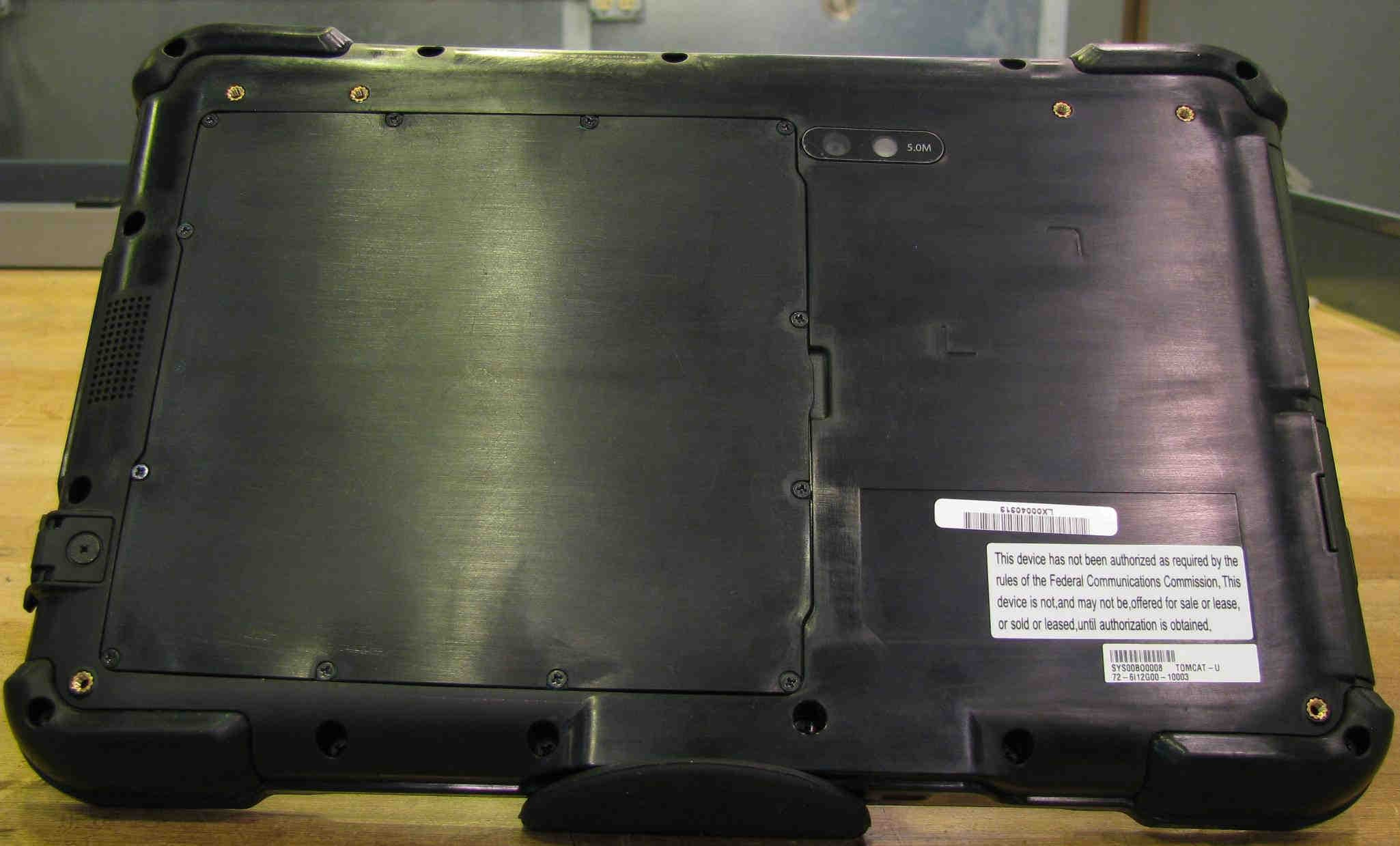
Q2GWG7550A
Aug 19, 2013Rugged Tablet PC
Equipment Class
NII - Unlicensed National Information Infrastructure TX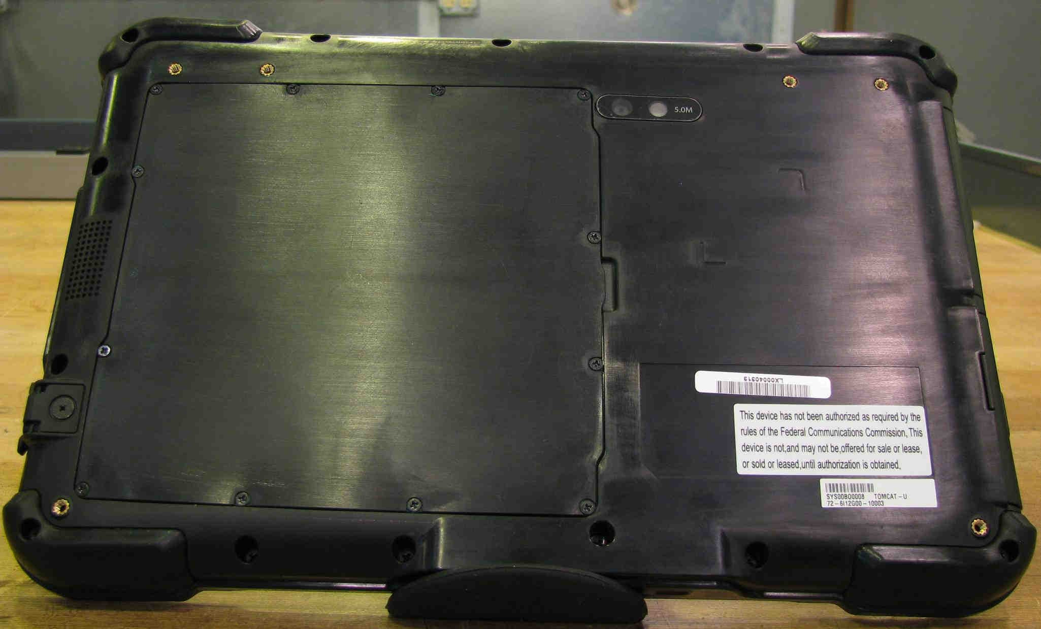
Q2GWG7550
Jul 15, 2013Rugged Tablet PC
Equipment Class
DTS - Digital Transmission System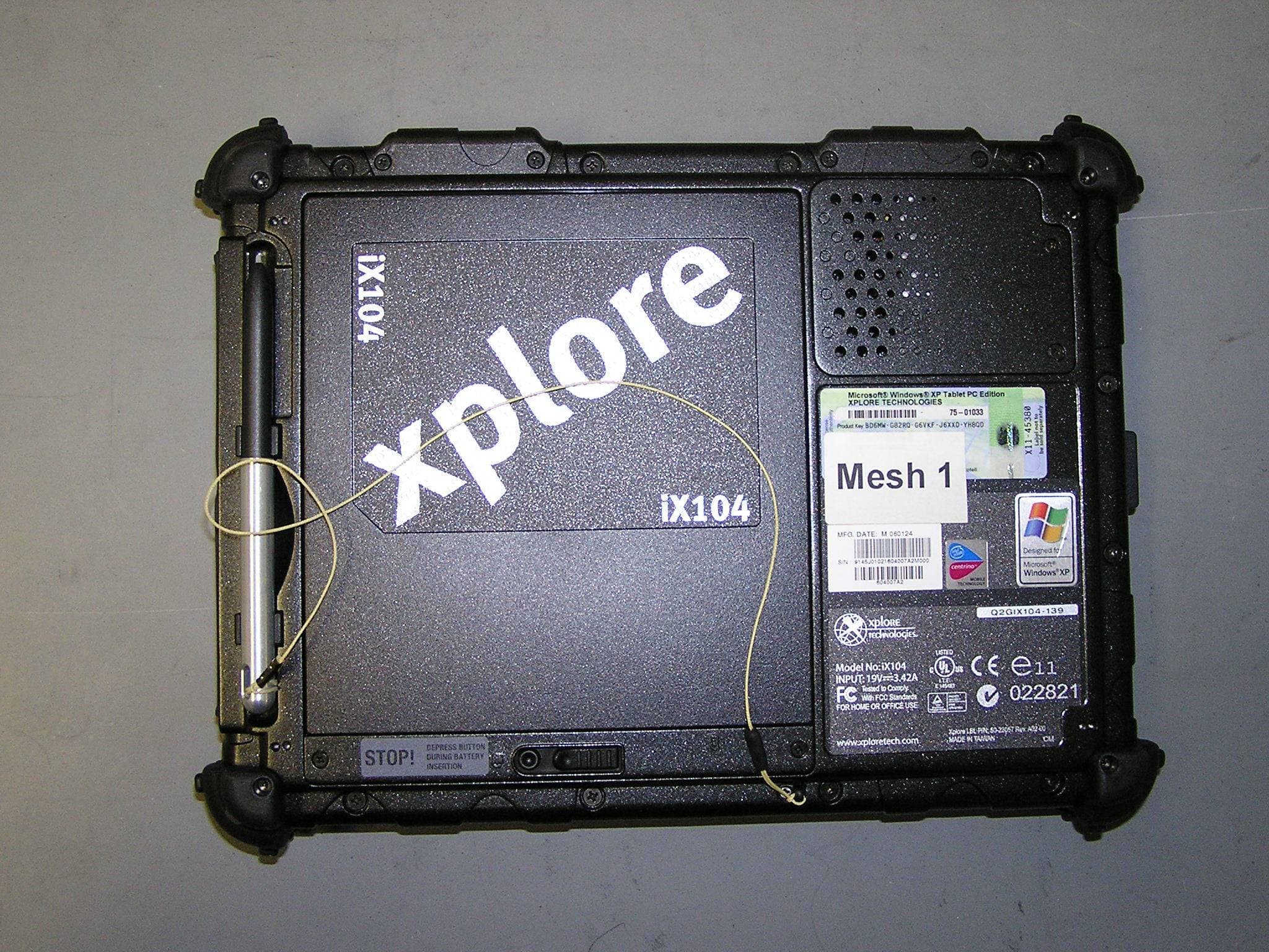
Q2GIX104-149
May 18, 2006Tablet PC with wireless transmitter
Equipment Class
DSS - Part 15 Spread Spectrum Transmitter
Q2GIX104-148
Mar 20, 2006Tablet PC with WLAN/GSM/EGPRS/WCDMA/BT transmitter
Equipment Class
DSS - Part 15 Spread Spectrum Transmitter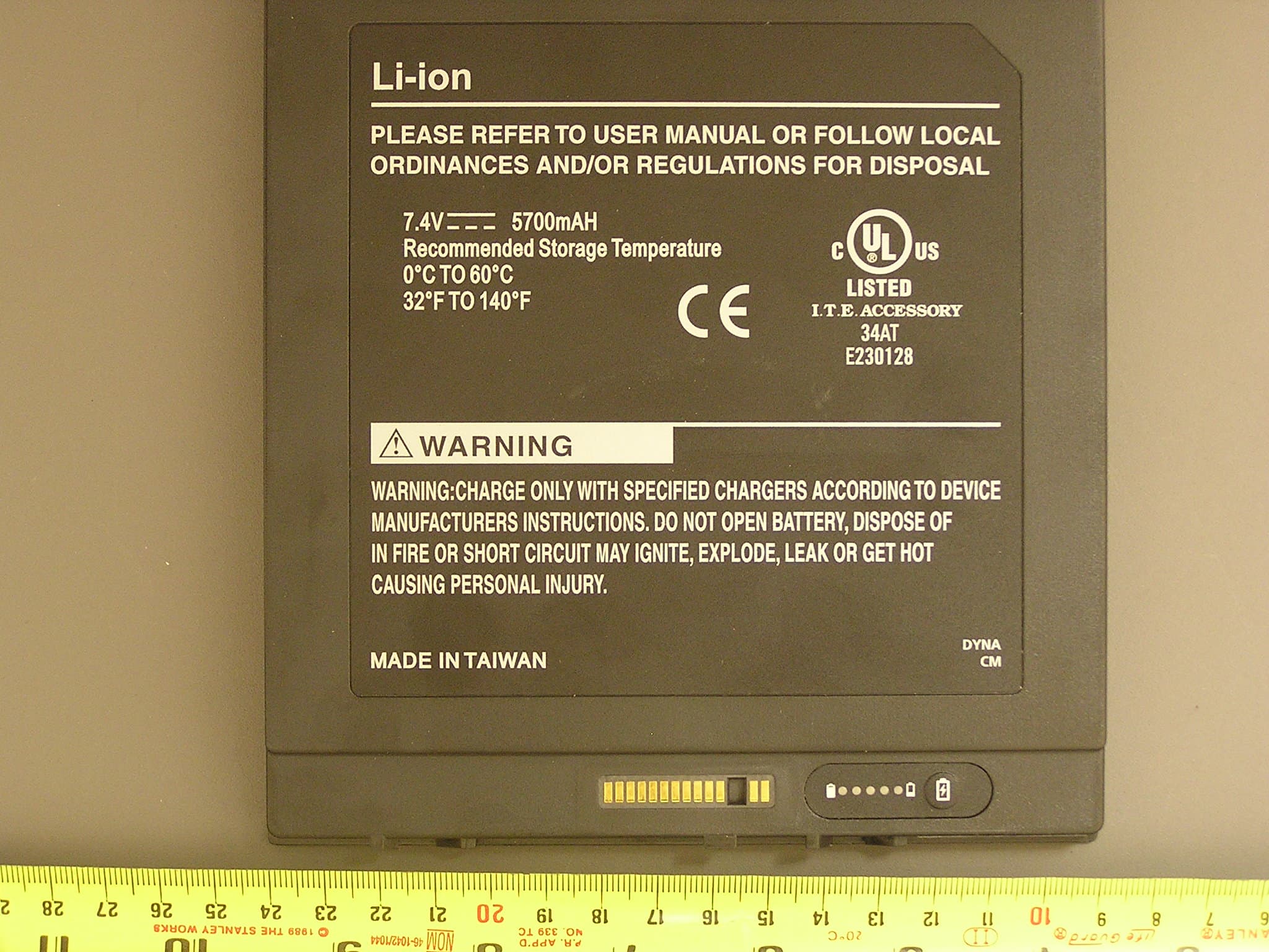
Q2GIX104-146
Mar 19, 2006Tablet PC with BT and GSM/EGPRS/WCDMA transmitters
Equipment Class
DSS - Part 15 Spread Spectrum Transmitter