Q2GIX104-117Tablet PC with GSM and WLAN radios
Xplore Technologies Corp.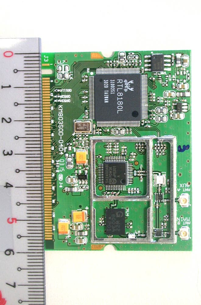
Click to zoom
Application Details
- Equipment Class
- DSS - Part 15 Spread Spectrum Transmitter
- Date of Grant
- Dec 16, 2003
- Application Purpose
- Original Equipment
- Date of Application
- Oct 16, 2003
- Equipment Note
- Tablet PC with GSM and WLAN radios
- Frequency Range
- 2412.00000000 - 2462.00000000
- Company
- Xplore Technologies Corp.
- Country
- United States
Documents & Files
Document Text
Text extracted from the exhibit documents filed with the FCC. Open a document above to read the original.
Users Manual
ix104USER’S HANDBOOK iX104 USER'S HANDBOOK 4 iX104 User’s Handbook Xplore Technologies ® has made every effort to ensure the accuracy and completeness of this document; however, because ongoing development efforts are made to continually improve the capabilities of our products, we cannot guarantee the accuracy of the contents of this document. We disclaim liability for errors, omissions, or future changes herein. Xplore and the Xplore logo are registered trademarks of Xplore Technologies Corp.; iX104 is a trademark of Xplore Technologies Corp. Kensington and MicroSaver are registered trademarks of the Kensington Technology Group. Microsoft is a registered trademark of Microsoft Corporation. Windows 2000 Professional, Windows XP Professional, and Windows XP Tablet PC Edition are trademarks of Microsoft Corporation. PCMCIA and CardBus are registered trademarks of the Personal Computer Memory Card International Association. Intel, Pentium, and SpeedStep are registered trademarks of Intel Corporation. Wi-Fi is a trademark of the Wireless Ethernet Compatibility Alliance (WECA). FireWire is a registered trademark of Apple Computer, Inc. ISODAMP is a registered trademark of Aearo Company. All other brands, product names, company names, trademarks and service marks used herein are property of their respective companies. Copyright © 2003 Xplore Technologies Corp. All rights reserved. No part of this publication may be copied, reproduced, or translated, without the prior written consent of Xplore Technologies. No part of this publication may be stored or transmitted in any electronic form without the prior consent of Xplore Technologies. Any unauthorized use is a violation of copyright laws. PN: 95-01016 Edition: Second, July 2003 DECLARATION OF CONFORMITY according to FCC Part 15 Responsible Party Name: Xplore Technologies Corp. Address: 14000 Summit Drive, Suite 900, Austin, Texas 78728 Telephone: 512.336.7797 Declares that product: Model Series: iX104 Complies with Part 15 of the FCC Rules iX104 User’s Handbook 5 This device complies with Part 15 of the FCC rules. Operation is subject to the following two conditions: (1) This device may not cause harmful interference, and, (2) This device must accept any interference received, including interference that may cause undesired operation. WARNING Changes or modifications to this unit not expressly approved by the party responsible for compliance may void the user’s authority to operate this equipment. For more information about FCC rules and their applicability to the iX104, see Appendix E, “Agency Notices.” Warranty Information The iX104 and iX104-TPC are backed by a standard 12-month International Limited Warranty. An extended International Limited Warranty is available. Check the service kit included with your computer for warranty terms and conditions. a 6 iX104 User’s Handbook Important safety information Before you use the iX104 or the iX104 dock, read these safety instructions and the operation instructions in this handbook. Failure to observe all these instructions voids the Limited Warranty and may lead to suspension or denial of services to the offender, or legal action, or both. Follow any special regulations governing the use of the computer and, if radio-enabled, always switch it off in areas where radio devices are forbidden or when the radio device can cause interference or danger. Always follow any safety laws and regulations pertaining to the use of cell phones and two-way radios, because these laws and regulations typically apply to the use of the wireless-enabled iX104. Observe all restrictions on the use of radio equipment in fuel depots (fuel storage and distribution areas), chemical plants, and wherever blasting operations are in progress or in any area in which restrictions on radio transmissions are imposed. Switch off the iX104 when in an aircraft. The iX104 is not FAA-approved for use on aircraft. The effect of the use of the iX104 in aircraft is unknown. Using the iX104 in an aircraft may affect aircraft instrumentation, communication, and performance; may disrupt the network; and may be illegal. Operating the wireless-enabled iX104 may interfere with the functioning of inadequately protected medical devices such as pacemakers. Consult a physician or the manufacturer of the medical device if you have any questions. Radio signals from your iX104 will not affect the operation of most modern equipment, but certain electronic equipment, including automotive systems, may not be shielded against radio signals from your iX104. Check with the manufacturer of your motor vehicle or the manufacturer’s representative to determine whether using the iX104 will present any safety issues. Avoid using the iX104 in any environment that requires your full attention, such as when driving a vehicle. If you need to use your iX104 while driving, have a passenger use it for you or find a safe location to halt your vehicle. iX104 User’s Handbook 7 WARNING Use only battery types specified in this handbook. Using any other type of battery can be dangerous and can disable the iX104. WARNING Do not use any dock or any other accessory or attachment that is not manufactured or supplied by Xplore or an authorized Xplore accessories supplier. Use of any accessory or attachment that is not supplied or approved for use with the iX104 by Xplore is not permitted because it may cause hazards. Operate the iX104 only from the type of power source indicated on the marking label. (See page 53 for more information about the battery and power supply.) Route power supply cords so that they are not likely to be walked on or pinched by items placed upon or against them. Pay particular attention to cords at plugs and convenience receptacles, and at the point where cords exit from the computer or its dock. Do not overload wall outlets, extension cords, or integral convenience receptacles because this can cause fire or electric shock. Unplug the iX104 and refer the iX10…
Text truncated - open the document above for the full version.
Users Manual
IEEE 802.11b WLAN miniPCI EM-200B OEM Installation Manual (The module is sold only to the OEM integrators & the manual is valid only for the OEM manufactures) Version: 1.0 April 2003 1 Copyright Statement No part of this publication may be reproduced, stored in a retrieval system, or transmitted in any form or by any means, whether electronic, mechanical, photocopying, recording or otherwise without the prior writing of the publisher. Windows ™ 98SE/2000/ME/XP are trademarks of Microsoft ® Corp. Pentium is trademark of Intel. All copyright reserved. 2 Federal Communication Commission Interference Statement This equipment has been tested and found to comply with the limits for a Class B digital device, pursuant to Part 15 of the FCC Rules. These limits are designed to provide reasonable protection against harmful interference in a residential installation. This equipment generates, uses and can radiate radio frequency energy and, if not installed and used in accordance with the instructions, may cause harmful interference to radio communications. However, there is no guarantee that interference will not occur in a particular installation. If this equipment does cause harmful interference to radio or television reception, which can be determined by turning the equipment off and on, the user is encouraged to try to correct the interference by one of the following measures: - Reorient or relocate the receiving antenna. - Increase the separation between the equipment and receiver. - Connect the equipment into an outlet on a circuit different from that to which the receiver is connected. - Consult the dealer or an experienced radio/TV technician for help. FCC Caution: To assure continued compliance, (example - use only shielded interface cables when connecting to computer or peripheral devices) any changes or modifications not expressly approved by the party responsible for compliance could void the user's authority to operate this equipment. This device complies with Part 15 of the FCC Rules. Operation is subject to the following two conditions: (1) This device may not cause harmful interference, and (2) This device must accept any interference received, including interference that may cause undesired operation. IMPORTANT NOTE: This module is restricted to mobile configuration. To comply with FCC RF exposure compliance requirements, the antenna used for this transmitter must be installed to provide a separation distance of at least 20 cm from all persons and must not be co-located or operating in conjunction with any other antenna or transmitter. This transmitter module must not be co-located or operating in conjunction with any other antenna or transmitter 3 TABLE OF CONTENTS 1. INTRODUCTION 4 2. HARDWARE INSTALLATION & ANTENNA INFORMATION5 CAUTION !! 6 3. CONNECTING TO AN EXISTING NETWORK 8 4. CREATING A NEW AD HOC NETWORK 10 5. CONFIGURATION 11 5.1 WIRELESS MODE 11 5.2 LINK INFO PAGE 12 5.3 CONFIGURATION PAGE 13 5.4 ENCRYPTION PAGE 14 5.5 SITESURVEY PAGE 15 5.6 VERSIONS 15 5.7 PROFILE 16 5.8 DEFAULT SETTINGS WINDOWS XP ZERO-CONFIGURATION 17 6. WIRELESS NETWORKING APPLICATIONS 18 6.1 SURVEYING THE NETWORK NEIGHBORHOOD 18 6.2 FILE SHARING 19 6.3 USING THE SHARED FOLDER 20 7. TROUBLESHOOTING 21 8. PRODUCT SPECIFICATION 22 4 1. Introduction Thank you for purchasing the IEEE802.11b WLAN miniPCI that provides the easiest way to wireless networking. This OEM Installation Manual contains detailed instructions in the operation of this product. Please keep this manual for future reference. System Requirements l A Personal Computer contains: - 32 MB memory or greater - 300 MHz processor or higher l Microsoft ® Win ™ 98SE/ME/2000/ XP 5 2. Hardware Installation & Antenna Information l Module is installed in the Personal Computer, located either under the keypad or on the bottom side of the Personal Computer (see the following diagrams). l Antennas are embedded in the top corners of the panel (see the two circles shown below) Important Note: This module is restricted to mobile configuration. The antennas of module should be installed and operated with minimum distance 20cm between the radiator and all persons. This transmitter must not be co-located or operating in conjunction with any other antenna or transmitter. The module is for OEM installation only and can not be sold to end user directly. Only the antenna types listed below can be used. 1. CA8-I (WNC) 2. 5600 (CLEVO) 3. 888E (CLEVO) 4. M300N (CLEVO) 6 Caution !! (1). This module cannot be bound in a tablet computer for RF exposure issues. (See label 1) (2). Due to the RF exposure issues, this module can be used in a laptop computer in normal operation, but cannot be used when it is put above the lap and the LCD screen is in the closed position. (See label 2) Label 1 Label 2 The device can’t be operated above the lap when the LCD is closed 7 (3). This module must be labeled with FCC ID. (See label 3) (4). If the FCC ID is not visible when the module is installed inside another device, then the outside of device must also display a label referring to the enclosed module. The exterior label can be “ Contains Transmitter Module FCC ID: NKREM200B” or similar wording. (See label 4) Please put Label 2 & Label 4 to the enclosure of end product to note the end user. Label 3 Label 4 8 3. Connecting to an Existing Network 1. Double click the shortcut icon of “IEEE802.11b WLAN miniPCI Utility” on the desktop, and the “IEEE802.11b WLAN miniPCI Utility” window will appear. 2. In the Windows System Tray, there is a communication-status icon that indicates different connection statuses by showing different colors. Green communication-status icon indicates the presence of a successful connection, and your network connection process is complete. 3. Red communication-status icon indicates that no connection is present. In this case, please go to “SiteSurvey” page and wait for a second (or click “Refresh” button) to get a list of all available networks. 4. From the …
Text truncated - open the document above for the full version.
Cover Letter(s)
Xplore Technologies, Inc. 14000 Summit Road Suite 900 Austin, TX 78728 888-44-XPLORE Page 1 of 1 10/10/2003 October 1, 2003 Federal Communication Commission Equipment Approval Service Attention: Authorization and Evaluation Division Reference: Xplore Technologies FCC ID: Q2GIX104-117 To Whom It May Concern: Subject: Request for Confidentiality Pursuant to Sections 0.457 (d)(1)(ii) and 0.459 of the Commission’s rules, the Applicant hereby requests confidential treatment of the Xplore Technologies supplied information accompanying this application. The confidential information includes the following: • Schematics • Block Diagrams • Bill of Materials • Operational Description • Tune-up procedure The materials contain trade secrets and proprietary information not customarily released to the public. Public disclosure of this information might be harmful to Xplore Technologies and provide unjustified benefits to our competitors. Xplore Technologies understands that pursuant to 0.457 (d)(1)(ii), disclosure of the Application and all accompanying documentation will not be made before the date of the grant. Xplore Technologies, Inc. 14000 Summit Road Suite 900 Austin, TX 78728 888-44-XPLORE Page 2 of 2 10/10/2003 Best regards, Douglas L. Fowler Sr. Project Engineer Xplore Technologies, Inc.
Cover Letter(s)
1 of 1 CETECOM Inc. 411 Dixon Landing Road Milpitas, CA 95035 U.S.A. Phone: + 1 408 586 6200 Fax: + 1 408 586 6299 e-mail: [email protected] URL: www.cetecom.com STATEMENT This filing constitutes a formal submittal and request for Equipment Authorization pursuant to Subpart C of Part 15, 22 & 24 of FCC rules (CFR 47) regarding two transmitters collocated in Tablet PC. Company Name: Xplore Technologies FCC ID: Q2GIX104-117 Tablet PC model# iX104 WLAN Model# KM8 Collocated with GSM module model# 1902G SUMMARY OF TESTING Xplore Tablet PC model# iX104 can be equipped with two different kind of radios; • RIM model# 1902G for GSM/GPRS function • Wistron NeWeb model# KM8 for WLAN function These radios are off-the shelf modules and have not been modified since the FCC ID has been granted. Tablet PC iX104 provides new antenna to the two modules integrated in it. These radios in iX104 are not user accessible. EMC/Radio Test Reports: Test report no. EMC_544FCC15.247_2003_KM8_CoL_GSM The above-mentioned test report cover all radiated measurements done on Tablet PC with WLAN collocated with GSM module. Tablet PC model# iX104 was tested with both radios ON to show compliance with FCC 15.247 limits only based upon the fact that FCC 15.247 limits are more stringent than FCC22/24 limits. Test report no. ISL-03LR007FC_Part-1/2/3 The above-mentioned test reports cover all conducted measurements required for WLAN Test report no. RIM-0204-04 The above-mentioned test report cover all conducted measurements for GSM module. Test report no. EMC_448-2003FCC22-24_IX104-11 The above-mentioned test report covers all radiated measurements done on Tablet PC with GSM module. 2 of 2 CETECOM Inc. 411 Dixon Landing Road Milpitas, CA 95035 U.S.A. Phone: + 1 408 586 6200 Fax: + 1 408 586 6299 e-mail: [email protected] URL: www.cetecom.com SAR Test Reports: Test report no. SAR_544_2003_FCC_850_1900_2450_RIM_KM8 This test report cover SAR testing done on Tablet PC with WLAN collocated with GSM module. Harpreet Sidhu EMC & Radio Engineer
External Photos
KM8 – Top view shielded KM8 – Top view unshielded KM8 – Bottom view
External Photos
iX104: Exterior - F ront iX104: Exterior - B ack FCC Label iX104: Exterior – B attery Pack Removed iX104: Antenna Locations Wide A r ea Network AntennaLocal Area NetworkAntenna iX104: I/O PCB
ID Label/Location Info
0.125 1.250 4X R 0.025 NOTES: 1. Material: Polycarbonate T= 0.127mm with matted texture 2. Material must be approved by UL, CSA 3. Adhesive Spec Refer to ES-811-RO5 Sony 303 or Toyo Df2700MR or Equiv 4. Print Color: Letters Silver ACD M808 Background Black ACD-M8010 and cool gray 11 5. Print Tolerance of dimensions +0.3/.03 LABEL, IX104, WIRELESS, KN8 + RIM1902 50-23045 A Xplore Technologies SCALE:2:1 SIZEDWG. NO. A REV. MATERIAL FINISH -- -- DO NOT SCALE DRAWINGAPPLICATION USED ONNEXT ASSY DIMENSIONS ARE IN INCHES TOLERANCES: FRACTIONAL ANGULAR: MACH BEND TWO PLACE DECIMAL THREE PLACE DECIMAL NAME DATE DRAWN CHECKED ENG APPR. MFG APPR. Q.A. SHEET 1 OF 1WEIGHT: COMMENTS: REVISIONS DESCRIPTION REV. DATEAPPROVED THE INFORMATION CONTAINED IN THIS DRAWING IS THE SOLE PROPERTY OF XPLORE TECHNOLOGIES. ANY REPRODUCTION IN PART OR AS A WHOLE WITHOUT THE WRITTEN PERMISSION OF XPLORE TECHNOLOGIES IS PROHIBITED. PROPRIETARY AND CONFIDENTIAL ZONE
Internal Photos
iX104: Antenna Cavities WAN Antenna LAN Antenna iX104: Interior View PCMCIASlot Mini-PCISlot 1902G KM8 iX104: Main Logic Board iX104: Keypad PCB iX104: I/O PCB iX104: I/O PCB Removed
RF Exposure Info
TTI-P-G 081/94-A0 Accredited according to ISO/IEC 17025 Bluetooth Qualification Test Facility (BQTF) FCC listed # 101450 IC recognized # 3925 CETECOM Inc. 411 Dixon Landing Road Milpitas, CA 95035 U.S.A. Phone: + 1 (408) 586 6200 Fax: + 1 (408) 586 6299 E-mail: [email protected] http://www.cetecom.com CETECOM Inc. is a Delaware Corporation with Corporation number: 2113686 Board of Directors: Dr. Harald Ansorge, Dr. Klaus Matkey, Hans Peter May V.2.16M-2002-03-12 \\stupendousman\rootappsdata\emc\projects_emc\xplore\544-2003_ix104_second set of cards\sar\rim_km8\sar_544_2003_fcc_850_1900_2450_rim_km8.doc © Copyright by CETECOM SAR Test Report No. SAR_544_2003_FCC_850_1900_2450_RIM_KM8 for the Xplore Technologies Tablet Computer Model Number: iX104 FCC ID: Q2G IX104-117 Date of Report: 10/07/2003 Date of issue: 10/07/2003 Report Copy No.: 01 SAR Test Report No. SAR_544_2003_FCC_850_1900_2450_RIM_KM8 Date of Report: 10/07/2003 Page 2 of 30 Error! Reference source not found. This report shall not be reproduced except in full without the written approval of: CETECOM Inc. SAR 411 Dixon Landing Road Milpitas, CA 95035 U.S.A. Contents 1 ASSESSMENT ...................................................................................................................4 2 ADMINISTRATIVE DATA...................................................................................................5 2.1 Identification of the Testing Laboratory Issuing the SAR Assessment Report ...............5 2.2 Identification of the Client...........................................................................................5 2.3 Identification of the Manufacturer...............................................................................5 3 EQUIPMENT UNDER INVESTIGATION (EUI)...................................................................6 3.1 Identification of the Equipment under Investigation ...................................................6 3.2 Front View of the Equipment under Investigation ......................................................7 4 SUBJECT OF INVESTIGATION ........................................................................................8 4.1 The IEEE Standard C95.1 and the FCC Exposure Criteria .......................................8 4.2 Distinction Between Exposed Population, Duration of Exposure and Frequencies...8 4.3 Distinction between Maximum Permissible Exposure and SAR Limits......................9 4.4 SAR Limit ...................................................................................................................9 5 THE FCC MEASUREMENT PROCEDURE .....................................................................10 5.1 General Requirements.............................................................................................10 5.2 Device Operating Next to a Person’s Ear ................................................................10 5.3 Test Positions ..........................................................................................................11 5.4 Test positions of device relative to head..................................................................11 5.5 Test to be Performed ...............................................................................................14 5.6 Body-worn and Other Configurations.......................................................................14 5.7 Procedure for assessing the peak spatial-average SAR .........................................15 5.8 Determination of the largest peak spatial-average SAR ..........................................17 6 THE MEASUREMENT SYSTEM ......................................................................................18 6.1 Robot system specification ......................................................................................18 6.2 Probe and amplifier specification .............................................................................19 6.3 Phantoms.................................................................................................................19 SAR Test Report No. SAR_544_2003_FCC_850_1900_2450_RIM_KM8 Date of Report: 10/07/2003 Page 3 of 30 Error! Reference source not found. This report shall not be reproduced except in full without the written approval of: CETECOM Inc. SAR 411 Dixon Landing Road Milpitas, CA 95035 U.S.A. 6.4 SAR measurement procedure .................................................................................20 6.5 SARA2 Interpolation and Extrapolation schemes ....................................................20 6.6 Interpolation of 2D area scan...................................................................................21 6.7 Extrapolation of 3D scan..........................................................................................21 6.8 Interpolation of 3D scan and volume averaging.......................................................21 7 UNCERTAINTY ASSESSMENT.......................................................................................23 7.1 Table of Measurement Uncertainty Values of SAR Evaluations..............................24 7.2 Table of Measurement Uncertainty Values for SAR System Verification ................25 8 TEST RESULTS SUMMARY............................................................................................26 8.1 Conducted Output Power.........................................................................................26 8.2 Test Positions and Configurations ...........................................................................26 8.3 2450 MHz band SAR Results for iX104 with KM8 ...................................................28 8.4 Validation Check Results .........................................................................................29 9 REFERENCES..................................................................................................................30 SAR Test Report No. SAR_544_2003_FCC_850…
Text truncated - open the document above for the full version.
RF Exposure Info
SAR Test Report No.: SAR_544_2003_FCC_850_1900_2450_RIM_KM8 Date of Report: 10/07/2003 Appendix A Plots Page 1 of 12 1902G 850 MHz band: Plot 1. Date: 04/03/2003 Temperature Air / Liquid: 21.0°C / 21.0°C Liquid mass density (ρ): 1 DCP 1 X=9, Y=13.6, Z=8.7 Probe S/N:0123 Air Factor X=346, Y=318, Z=386 Probe S/N:0123 liquid/air conversion Factor 0.466 Simulated tissue dielectric parameters: ε r : 55.5 σ: 0.985 Test Position: bystander 1 cm Channel / Frequency 192 / 836.6 MHz Maximum 1 gram SAR: 0.315W/Kg Maximum 10 gram SAR: 0.215W/Kg Power reference start: 0.170W/Kg Power reference end 0.170W/Kg Power reference change 2 0.00% 1 DCP: Diode compression potential for different types of modulation is determined during the calibration of the probe. See section 6.2 of this report Probe and Amplifier Specification. Crest factor is not used. 2 The power reference change is calculated by the test system with more digits than indicated in the power reference start and end values. SAR Test Report No.: SAR_544_2003_FCC_850_1900_2450_RIM_KM8 Date of Report: 10/07/2003 Appendix A Plots Page 2 of 12 Plot 2. Date: 04/03/2003 Temperature Air / Liquid: 21.0°C / 21.0°C Liquid mass density (ρ): 1 DCP 1 X=9, Y=13.6, Z=8.7 Probe S/N:0123 Air Factor X=346, Y=318, Z=386 Probe S/N:0123 liquid/air conversion Factor 0.466 Simulated tissue dielectric parameters: ε r : 55.5 σ: 0.985 Test Position: lap Channel / Frequency 192 / 836.6 MHz Maximum 1 gram SAR: 0.140W/Kg Maximum 10 gram SAR: 0.103W/Kg Power reference start: 0.075W/Kg Power reference end 0.077W/Kg Power reference change 2 3.31% 1 DCP: Diode compression potential for different types of modulation is determined during the calibration of the probe. See section 6.2 of this report Probe and Amplifier Specification. Crest factor is not used. 2 The power reference change is calculated by the test system with more digits than indicated in the power reference start and end values. SAR Test Report No.: SAR_544_2003_FCC_850_1900_2450_RIM_KM8 Date of Report: 10/07/2003 Appendix A Plots Page 3 of 12 Plot 3. Date: 04/03/2003 Temperature Air / Liquid: 21.0°C / 21.0°C Liquid mass density (ρ): 1 DCP 1 X=9, Y=13.6, Z=8.7 Probe S/N:0123 Air Factor X=346, Y=318, Z=386 Probe S/N:0123 liquid/air conversion Factor 0.466 Simulated tissue dielectric parameters: ε r : 56.12 σ: 0.971 Test Position: lap Channel / Frequency 128 / 824.2 MHz Maximum 1 gram SAR: 0.222W/Kg Maximum 10 gram SAR: 0.182W/Kg Power reference start: 0.105W/Kg Power reference end 0.101W/Kg Power reference change 2 -3.31% 1 DCP: Diode compression potential for different types of modulation is determined during the calibration of the probe. See section 6.2 of this report Probe and Amplifier Specification. Crest factor is not used. 2 The power reference change is calculated by the test system with more digits than indicated in the power reference start and end values. SAR Test Report No.: SAR_544_2003_FCC_850_1900_2450_RIM_KM8 Date of Report: 10/07/2003 Appendix A Plots Page 4 of 12 Plot 4. Date: 04/03/2003 Temperature Air / Liquid: 21.0°C / 21.0°C Liquid mass density (ρ): 1 DCP 1 X=9, Y=13.6, Z=8.7 Probe S/N:0123 Air Factor X=346, Y=318, Z=386 Probe S/N:0123 liquid/air conversion Factor 0.466 Simulated tissue dielectric parameters: ε r : 55.38 σ: 0.979 Test Position: lap Channel / Frequency 251 / 848.8 MHz Maximum 1 gram SAR: 0.204W/Kg Maximum 10 gram SAR: 0.071W/Kg Power reference start: 0.028W/Kg Power reference end 0.029W/Kg Power reference change 2 1.91% 1 DCP: Diode compression potential for different types of modulation is determined during the calibration of the probe. See section 6.2 of this report Probe and Amplifier Specification. Crest factor is not used. 2 The power reference change is calculated by the test system with more digits than indicated in the power reference start and end values. SAR Test Report No.: SAR_544_2003_FCC_850_1900_2450_RIM_KM8 Date of Report: 10/07/2003 Appendix A Plots Page 5 of 12 1902G 1900 MHz band: Plot 5. Date: 04/03/2003 Temperature Air / Liquid: 21.0°C / 21.0°C Liquid mass density (ρ): 1 DCP 1 X=9, Y=13.6, Z=8.7 Probe S/N:0123 Air Factor X=346, Y=318, Z=386 Probe S/N:0123 liquid/air conversion Factor 0.610 Simulated tissue dielectric parameters: ε r : 53.25 σ: 1.580 Test Position: bystander 1 cm Channel / Frequency 661 / 1880 MHz Maximum 1 gram SAR: 0.295W/Kg Maximum 10 gram SAR: 0.150W/Kg Power reference start: 0.079W/Kg Power reference end 0.079W/Kg Power reference change 2 -0.00% 1 DCP: Diode compression potential for different types of modulation is determined during the calibration of the probe. See section 6.2 of this report Probe and Amplifier Specification. Crest factor is not used. 2 The power reference change is calculated by the test system with more digits than indicated in the power reference start and end values. SAR Test Report No.: SAR_544_2003_FCC_850_1900_2450_RIM_KM8 Date of Report: 10/07/2003 Appendix A Plots Page 6 of 12 Plot 6. Date: 04/03/2003 Temperature Air / Liquid: 21.0°C / 21.0°C Liquid mass density (ρ): 1 DCP 1 X=9, Y=13.6, Z=8.7 Probe S/N:0123 Air Factor X=346, Y=318, Z=386 Probe S/N:0123 liquid/air conversion Factor 0.610 Simulated tissue dielectric parameters: ε r : 53.25 σ: 1.580 Test Position: lap Channel / Frequency 661 / 1880 MHz Maximum 1 gram SAR: 0.054W/Kg Maximum 10 gram SAR: 0.028W/Kg Power reference start: 0.010W/Kg Power reference end 0.010W/Kg Power reference change 2 -0.00% 1 DCP: Diode compression potential for different types of modulation is determined during the calibration of the probe. See section 6.2 of this report Probe and Amplifier Specification. Crest factor is not used. 2 The power reference change is calculated by the test system with more digits than indicated in the power reference start and end values. SAR Test Report No.: SAR_544_2003_FCC_850_1900_2450_RIM_KM8 Date of Report: 10/07/2003 Appendix A Plots Page 7 of 12 Plot 7. Date: 04/03/2003 Temperature Air / Liquid: 21.0°C / 21.0°C Liquid mass density (ρ): 1 DCP…
Text truncated - open the document above for the full version.
RF Exposure Info
SAR Test Report No.: SAR_544_2003_FCC_850_1900_2450_RIM_KM8 Date of Report 10/07/2003 Appendix B Page 1 of 9 Appendix B: Photos EUT Photos: Photo 1. Antenna locations SAR Test Report No.: SAR_544_2003_FCC_850_1900_2450_RIM_KM8 Date of Report 10/07/2003 Appendix B Page 2 of 9 Photo 2. EUT front SAR Test Report No.: SAR_544_2003_FCC_850_1900_2450_RIM_KM8 Date of Report 10/07/2003 Appendix B Page 3 of 9 Photo 3. EUT back SAR Test Report No.: SAR_544_2003_FCC_850_1900_2450_RIM_KM8 Date of Report 10/07/2003 Appendix B Page 4 of 9 Setup Photos Photo 4. 2450 MHz antenna bystander position SAR Test Report No.: SAR_544_2003_FCC_850_1900_2450_RIM_KM8 Date of Report 10/07/2003 Appendix B Page 5 of 9 Photo 5. bystander position distance SAR Test Report No.: SAR_544_2003_FCC_850_1900_2450_RIM_KM8 Date of Report 10/07/2003 Appendix B Page 6 of 9 Photo 6. 2450 MHz antenna lap position SAR Test Report No.: SAR_544_2003_FCC_850_1900_2450_RIM_KM8 Date of Report 10/07/2003 Appendix B Page 7 of 9 Photo 7. GPRS antenna bystander position SAR Test Report No.: SAR_544_2003_FCC_850_1900_2450_RIM_KM8 Date of Report 10/07/2003 Appendix B Page 8 of 9 Photo 8. GPRS antenna lap position SAR Test Report No.: SAR_544_2003_FCC_850_1900_2450_RIM_KM8 Date of Report 10/07/2003 Appendix B…
Text truncated - open the document above for the full version.
Contact Information
Applicant
David J Ball(Senior Regulatory and Compliance Engineer)
Technical Contact
CETECOM Inc.Lothar Schmidt
[email protected]408 586 6214
411 Dixon Landing Road · Milpitas, California · United States
Non-Technical Contact
CETECOM Inc.Lothar Schmidt
[email protected]408 586 6214
Test Firm
Cetecom Inc.Lothar Schmidt
Technical Specifications
| # | Rule Parts | Frequency Range | Power Output |
|---|---|---|---|
| 1 | 15C | 2.41 GHz - 2.46 GHz | 83.00 mW |
Other Applications from Xplore Technologies Corp.
Q2GWG7550A
Aug 19, 2013Rugged Tablet PC
Equipment Class
NII - Unlicensed National Information Infrastructure TX
Q2GWG7550
Jul 15, 2013Rugged Tablet PC
Equipment Class
DTS - Digital Transmission System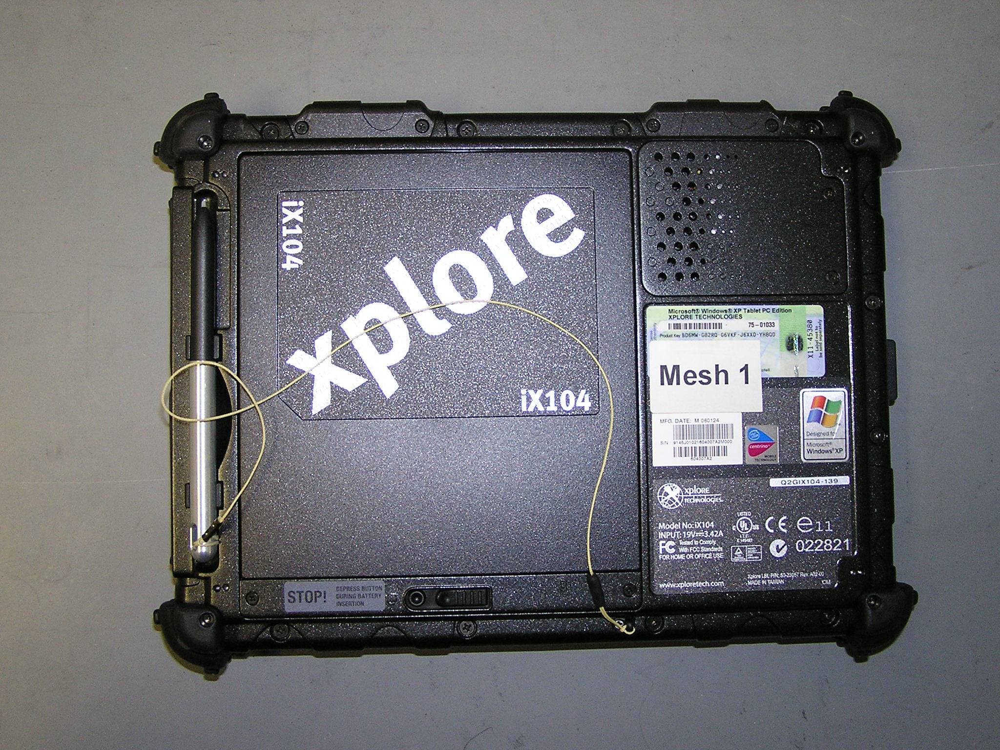
Q2GIX104-149
May 18, 2006Tablet PC with wireless transmitter
Equipment Class
DSS - Part 15 Spread Spectrum Transmitter
Q2GIX104-148
Mar 20, 2006Tablet PC with WLAN/GSM/EGPRS/WCDMA/BT transmitter
Equipment Class
DSS - Part 15 Spread Spectrum Transmitter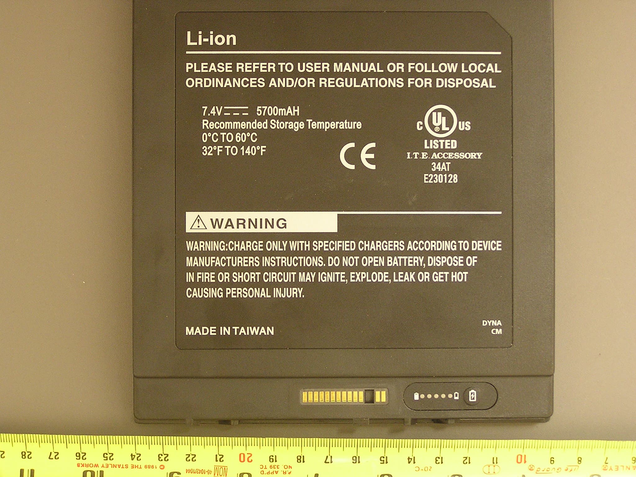
Q2GIX104-146
Mar 19, 2006Tablet PC with BT and GSM/EGPRS/WCDMA transmitters
Equipment Class
DSS - Part 15 Spread Spectrum Transmitter