Q2I19238Remote Control of Wireless Door Chime
FOSHAN SHUNDE ADVANTE ELECTRON LTD.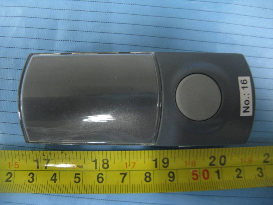
Click to zoom
Application Details
- Equipment Class
- DSC - Part 15 Security/Remote Control Transmitter
- Date of Grant
- Aug 05, 2011
- Application Purpose
- Original Equipment
- Date of Application
- Aug 05, 2011
- Equipment Note
- Remote Control of Wireless Door Chime
- Frequency Range
- 433.92000000 - 433.92000000
- Country
- China
Documents & Files
Document Text
Text extracted from the exhibit documents filed with the FCC. Open a document above to read the original.
Users Manual
1. Main Features 2. Panel Function A. Push B. Receiver C. Button Function 3. Operation Instruction A. Clock Setting B. Alarm Setting C. 12/24 mode & C/ F Shift 4. Wireless Date Search & Receive 5. Signal Icon 6. Temperature Icon 7. Trouble Shooting Instruction Manual Index 1. Main Features 12 12 A. 32 sounds 24 polyphonic, LED indicator in receiver B. Wide LCD display Time, Indoor/Outdoor Temperature C. Time with 12/24 mode shift, alarms can ring for 1 minute, two alarms both are available. D. Can display the current environment temperature (indoors and outdoors). The temperature range: -20.0 C~90.0 C (-4.0 F~194.0 F). 2. Panel Function A. Push B. Receiver 12 Wireless Door Chime with Thermometer&Clock 34 1. Push C. Button Function B. [Reset]: Press and reset the push, after 7 secs, the push will transmit updated temperature data to the receiver. A.[Push]: Press and initiate the door bell. F. [SELECT]: Press to select 32 melodies. 2.Receiver B. [SET]: In normal status, press for 12/24 mode shift, pressing more than 2 seconds to set Time/Alarm. A. [MODE]: Time, Alarm 1, Alarm 2. C. [UP]: In normal status, press to activate Alarm1, Alarm2 or both. In setting status, press to put forward the time. D. [DOWN]: In setting status, press to put backward the time. E. [MEM]: Press to shift Max/Min temperature respectively for indoors and outdoors. Pressing for more than 2 secs to erase the record of Max. & Min. temperature data. G. [ C/ F]: Press to shift C/ F degree. Press 2 secs to re-start the receipt of outdoor temperature from the push unit. H.[Reset]: Press to reset the system both for time and thermometer. 3. Operation Instruction A. Clock Setting In normal status, press [SET] key more than 2 seconds to set time and date. The setting sequence is hour and minute, press [UP] key and [DOWN] key to change the flashing digit. After setting, press [SET] key or no operation for 10 seconds, it will exit and display the current setting time. B. Alarm Setting In normal status, press [MODE] to set the Alarm1, then press [SET] for 2 secs, set the alarm time. Same as the time setting. Press [SET] to settle the setting. Re-press [MODE] can start setting of Alarm2, same as the Alarm1 setting. C. 12/24 mode & C/ F Shift In normal status, press SET key to shift from 12/24 hour mode. 4. Wireless Date Search & Receive After reload of batteries or press reset on the receiver, the receiver will begin to search wireless data for 5 mins. After reload of batteries or press reset on the push, the push will transmit outdoor temperature data to receiver one time per 83 secs. Once the receiver can receive the data, the LCD will display the ourdoor temperature and will update the data per 83 secs. Otherwise the LCD will display -----means can not receive any data from push, record is blank. 3 4 ÕýÔÚËÑÑ°ÐźŠ³É¹¦½ÓÊÕÐźŠûÊÕμ½ÐźŠ5. Signal Icon Data Receiving Data Received Fail to Receive 6. Temperature Icon 7. Trouble Shooting A. Time display is not clear, press the [Reset] to re-start the clock and thermometer systems. If it still can not work, please change with new batteries. B. Outdoor is blank, press the [ ] to re-start the receive of outdoor temperature from the push unit. If it still can not work, press [Reset] on the push to sent outdoor temperature data to the receiver at once. C. To change the batteries for receiver, user need to reset the clock if the changing time is over 40 secs. C/ F 5 Temperature Trend Up Steady Down FCC Caution: Any Changes or modifications not expressly approved by the party responsible for compliance could void the user's authority to operate the equipment. This device complies with part 15 of the FCC Rules. Operation is subject to the following two conditions: (1) This device may not cause harmful interference, and (2) this device must accept any interference received, including interference that may cause undesired operation.
External Photos
EXHIBIT B - EUT EXTERNAL PHOTOGRAPHS EUT– Top View EUT– Bottom View EUT– Side View
ID Label/Location Info
EXHIBIT A - FCC ID LABELING AND LOCATION FCC ID Label FCC ID Label Location
Internal Photos
EXHIBIT C - EUT INTERNAL PHOTOGRAPHS EUT - Cover off View EUT - Main Board Top View EUT - Main Board Bottom View EUT - Antenna View
Test Report
Note: This test report is prepared for the customer shown above and for the equipment described herein. It may not be duplicated or used in part without prior written consent from Bay Area Compliance Laboratories Corp. This report must not be used by the customer to claim product certification, approval, or endorsement by NVLAP*, or any agency of the Federal Government. * This report contains data that are not covered by the NVLAP accreditation and are marked with an asterisk “★” (Rev.2) TEST REPORT For Shunde Advante Electron Ltd. North Second XinXi Road, LunJiao Industrial Avenue, LunJiao, Shunde, Foshan, Guangdong, China FCC PART 15.231 FCC ID: Q2I19238 Report Type: Original Report Product Type: Remote Control of Wireless Door Chime Test Engineer: Walt Kang Report Number: RDG110627005-00 Report Date: 2011-08-04 Reviewed By: Merry Zhao EMC Engineer Test Laboratory: Bay Area Compliance Laboratories Corp. (Shenzhen) 6/F, the 3rd Phase of WanLi Industrial Building, ShiHua Road, FuTian Free Trade Zone Shenzhen, Guangdong, China Tel: +86-755-33320018 Fax: +86-755-33320008 www.baclcorp.com.cn Bay Area Compliance Laboratories Corp. (Shenzhen) FCC ID: Q2I19238 Report No.: RDG110627005-00 Page 2 of 18 FCC Part15.231 Test Report TABLE OF CONTENTS GENERAL INFORMATION.......................................................................................................................................3 PRODUCT DESCRIPTION FOR EQUIPMENT UNDER TEST (EUT) ....................................................................................3 OBJECTIVE...................................................................................................................................................................3 RELATED SUBMITTAL(S)/GRANT(S).............................................................................................................................3 TEST METHODOLOGY..................................................................................................................................................3 TEST FACILITY.............................................................................................................................................................3 SYSTEM TEST CONFIGURATION ..........................................................................................................................5 JUSTIFICATION.............................................................................................................................................................5 SPECIAL ACCESSORIES.................................................................................................................................................5 EQUIPMENT MODIFICATIONS.......................................................................................................................................5 CONFIGURATION OF TEST SETUP.................................................................................................................................5 BLOCK DIAGRAM OF TEST SETUP................................................................................................................................5 SUMMARY OF TEST RESULTS ...............................................................................................................................6 FCC §15.203 - ANTENNA REQUIREMENT.............................................................................................................7 APPLICABLE STANDARD..............................................................................................................................................7 FCC §15.205, §15.209, §15.231 (B) - RADIATED EMISSIONS ...............................................................................8 MEASUREMENT UNCERTAINTY....................................................................................................................................8 EUT SETUP..................................................................................................................................................................8 EMI TEST RECEIVER SETUP.........................................................................................................................................9 TEST EQUIPMENT LIST AND DETAILS...........................................................................................................................9 TEST PROCEDURE........................................................................................................................................................9 APPLICABLE STANDARD............................................................................................................................................10 CORRECTED AMPLITUDE & MARGIN CALCULATION.................................................................................................10 TEST RESULTS SUMMARY..........................................................................................................................................10 TEST DATA................................................................................................................................................................10 FCC §15.231(C) – 20 DB BANDWIDTH TESTING ................................................................................................12 REQUIREMENT...........................................................................................................................................................12 TEST EQUIPMENT LIST AND DETAILS.........................................................................................................................12 TEST PROCEDURE......................................................................................................................................................12 TEST DATA....................................................................................................................................…
Text truncated - open the document above for the full version.
Test Setup Photos
EXHIBIT D - TEST SETUP PHOTOGRAPHS Radiated Emission – Front View (Below 1 GHz) Radiated Emission – Rear View (Below 1 GHz) Radiated Emission – Front View (Above 1 GHz) Radiated Emission – Rear View (Above 1 GHz)
Contact Information
Applicant
Steven Zou(Technical Manager)
Test Firm
Bay Area Compliance Laboratory Corp. (Shenzhen)John Chan
Technical Specifications
| # | Rule Parts | Frequency Range | Power Output |
|---|---|---|---|
| 1 | 15.231 | 433.92 MHz - 433.92 MHz | - |
Other Applications from FOSHAN SHUNDE ADVANTE ELECTRON LTD.
Q2I202402Q
Sep 19, 2024Wireless Door Chime
Equipment Class
DSC - Part 15 Security/Remote Control Transmitter
Q2I2024FO
Sep 19, 2024Kinetic Wireless Doorbell
Equipment Class
DSC - Part 15 Security/Remote Control Transmitter
Q2I202401G
Sep 19, 2024Wireless Door Chime
Equipment Class
DSC - Part 15 Security/Remote Control Transmitter
Q2I2023D1
Jul 16, 2023Wireless Door Chime
Equipment Class
DSC - Part 15 Security/Remote Control Transmitter
Q2I202101
Apr 30, 2021Kinetic Wireless Doorbell
Equipment Class
DSC - Part 15 Security/Remote Control Transmitter