Q2I2020Q2Wireless Door Chime
FOSHAN SHUNDE ADVANTE ELECTRON LTD.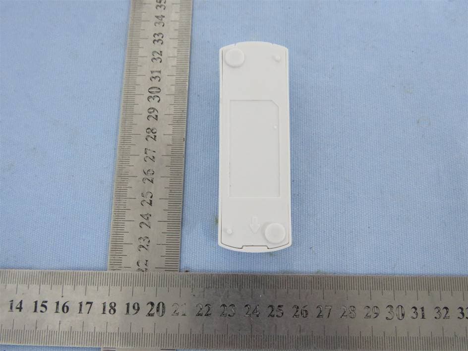
Click to zoom
Application Details
- Equipment Class
- DSC - Part 15 Security/Remote Control Transmitter
- Date of Grant
- May 07, 2020
- Application Purpose
- Original Equipment
- Date of Application
- May 07, 2020
- Equipment Note
- Wireless Door Chime
- Frequency Range
- 433.92000000 - 433.92000000
- Country
- China
Documents & Files
Document Text
Text extracted from the exhibit documents filed with the FCC. Open a document above to read the original.
Users Manual
of the push button (See Figure 3 — Mounting hole locations) and into the surface of the selected location. 5. Secure with the two screws provided. 6. Press front housing onto back cover. 7. Test operation. If Doorbell does not work, see TROUBLESHOOTING. Temporary push button (transmitter) mounting instructions 1. Clean the mounting location for the push button with a mixture of 50% water and 50% isopropyl alcohol. 2. Remove protective backing from one side of the adhesive pad and attach it to the back plate of the push button. 3. Remove protective backing from the other side of the adhesive pad and press the back plate to the cleaned mounting location. Hold in place for a few seconds to allow for a secure bond. Doorbell (receiver) mounting instructions NOTE: Avoid mounting on metal surfaces, as it may result in a reduced range of reception. 1. Select Doorbell mounting location. 2. Using the Doorbell mounting template on the package insert card, drill two holes with 3/32" drill bit in marked keyhole slot locations (See Figure 2). 3. Insert the two 3x25mm screws included, into the holes, setting the screw heads extending about ¼" from mounting surface. 4. Place the Doorbell unit’s keyhole slots over the screws and press down on the Doorbell unit to secure it. Extra Doorbell receivers and push buttons available at www.byjasco.com. Troubleshooting If the Doorbell does not work: 1. Make sure push button switch is pressed down and held for at least 1 second. 2. Verify battery installation is correct, noting polarity. 3. Try a fresh battery in push button. 4. Make sure Doorbell is no further than 150 feet away from push button. 5. Ensure push button is not mounted on metal, near metal studs or near the floor. 6. Try a new location for the Doorbell. 7. If the Doorbell and push button(s) do not operate, repeat the electronic pairing process of the push button(s) to the Doorbell in steps A-F below. A. To clear settings: press and hold the pairing button on the bottom of the Doorbell while installing the third battery. B. Once the last battery is installed, release the pairing button. C. Press and hold the pairing button again. You will hear the “Dingdong” melody twice, and then the double beep to alert you the Doorbell is ready to pair with the push button. Release the pairing button. D. Press and release the push button (See Figure 4). You will hear one beep letting you know the Doorbell accepted the signal. E. Wait 10 seconds and you will hear the double beep again to alert you the Doorbell is now paired with the push button. F. Press the push button to test. Functional range may be adversely affected by one or more of the following factors: weather, radio frequency interference, low transmitter battery or obstructions between the transmitter and receiver. This device complies with Part 15 of the FCC rules. Operation is subject to the following two conditions: (1) this device may not cause harmful interference, and (2) this device must accept any interference received, including interference that may cause undesired operation. FCC NOTE: The manufactur er is not responsible for any radio or TV interference caused by unauthorized modifications to this equipment. Such modifications could void the user’s authority to operate the equipment. NOTE: This equipment has been tested and found to comply with the limits for a Class B digital device, pursuant to Part 15 of the FCC Rules. These limits are designed to provide reasonable protection against harmful interference in a residential installation. This equipment generates, uses and can radiate radio frequency energy and, if not installed and used in accordance with the instructions may cause harmful interference to radio communications. However, there is no guarantee that interference will not occur in a particular installation. If this equipment does cause harmful interference to radio or television reception, which can be determined by turning the equipment off and on, the user is encouraged to try to correct the interference by one or more of the following measures: • Reorient or relocate the receiving antenna. • Increase the separation between the equipment and receiver. • Connect the equipment into an outlet on a circuit different from that to which the receiver is connected. • Consult the dealer or an experienced radio/TV technician for help. For technical support contact Jasco Products Company at 1-800-654-8483 or www.byjasco.com. Installation instructions Required tools: #2 Phillips screwdriver, small flat blade screwdriver, and 1/16" and 3/32" drill bit (not included). The wireless Doorbell kit has two components: Installing battery in push button (transmitter) 1. Remove the front cover of the push button housing by pushing a flat blade screwdrivier into the slot at the bottom of the push button housing (See Figure 1). 2. Install the CR2032 battery (included) with the positive (+) side up. 3. Keep the front cover off the push button until melody selection is complete. NOTE: The Doorbell and push button(s) have been electronically paired during production. Once the battery is installed in the push button and Doorbell receiver, press the push button(s) to ensure that the push button(s) cause the Doorbell to operate. IF DOORBELL DOES NOT SOUND, SEE TROUBLESHOOTING. Melody selection setting Select the melody by pushing the melody selection button located inside the push button housing (See Figure 1). Press and release the melody selection button until you hear the desired melody. Table 1 shows the order the melodies will be heard. The last melody played will be your selected Doorbell melody. Volume adjustment There are four volume settings on this Doorbell. 1. To adjust the volume, press and release the pairing button on the Doorbell or push the push button to play the melody. 2. While melody is playing, press and release the volume button on the Doorbell to select the desired sound level. Push button (transmitter) mounting instructions NOTE: Avoi…
Text truncated - open the document above for the full version.
External Photos
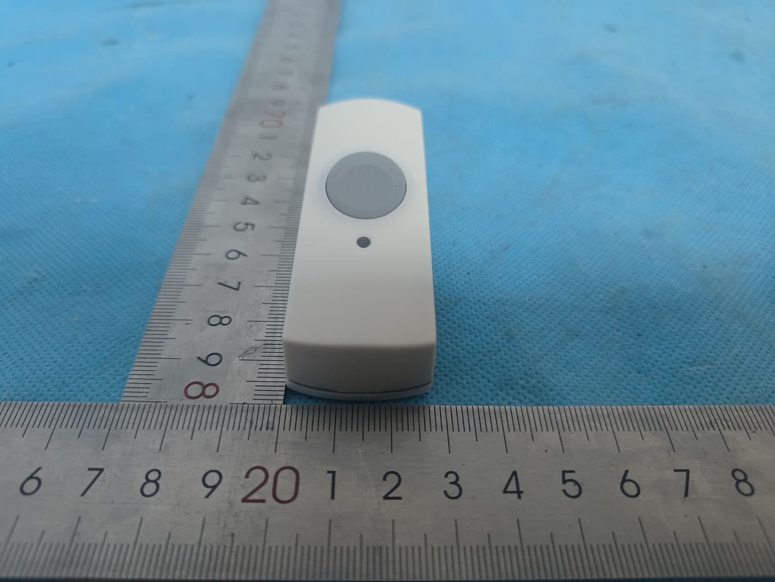
FCC ID: Q2I2020Q2 External photos FCC ID: Q2I2020Q2 FCC ID: Q2I2020Q2
ID Label/Location Info
FCC ID: Q2I2020Q2 Label & location
Internal Photos
FCC ID: Q2I2020Q2 Internal photos FCC ID: Q2I2020Q2 RF Antenna FCC ID: Q2I2020Q2 RF Chip
Operational Description
Shunde Advante Electron Ltd. Declaration concerning Antenna Specification It is hereby declared that the product Model No.: Q2, 19249, 19301 FCC ID: Q2I2020Q2 fulfills the requirement in FCC test relating to the antenna type. The device specified above confirms to the FCC recommendations for Integral antenna type(s) described below: Model No. of antenna: Ant Type of antenna: Integral antenna Gain of the antenna: 0.3 dBi Frequency range: 433.92MHz The mounting of the antenna is fixed to the radio module and no other antenna should be used. Company name: Shunde Advante Electron Ltd. Address: North Second XinXi Road, LunJiao Industrial Avenue, LunJiao City: Shunde,Foshan, Guangdong ZIP / Postal code: Country: China Place: Steven Date: 2019-04-29 Signature:
RF Exposure Info
Dongguan Nore Testing Center Co., Ltd. Report No.: NTC2004147FV00 FCC ID: Q2I2020Q2 RF EXPOSURE EVALUATION EUT Specification EUT Wireless Door Chime Model Name Q2, 19249, 19301 Frequency band (Operating) WLAN: 2.412GHz ~ 2.462GHz WLAN: 5.18GHz ~ 5.32GHz / 5.50GHz ~ 5.70GHz WLAN: 5.745GHz ~ 5825GHz Others(433.92MHz) Device category Portable (<20cm separation) Mobile (>20cm separation) Others ___ Antenna diversity Single antenna Multiple antennas Tx diversity Rx diversity Tx/Rx diversity Max. output power 89.02 dBuV/m (-6.24dBm)( 0.24mW) Antenna gain 0.3dBi Evaluation applied MPE Evaluation SAR Evaluation Dongguan Nore Testing Center Co., Ltd. Report No.: NTC2004147FV00 FCC ID: Q2I2020Q2 Standard Requirement Portable Device According to §15.247(i) and §1.1307b(1), systems operating under the provisions of this section shall be operated in a manner that ensures that the public is not exposed to radio frequency energy levels in excess of the Commission’s guidelines. See KDB 447498 D01 General RF Exposure Guidance v05, section 4.3.1. The 1-g and 10-g SAR test exclusion thresholds for 100 MHz to 6 GHz at test separation distances ≤ 50 mm are determined by: [(max. power of channel, including tune-up tolerance, mW)/(min. test separation distance, mm)] ·[√f(GHz)] ≤ 3.0 for 1-g SAR and ≤ 7.5 for 10-g extremity SAR, 16 where ·f(GHz) is the RF channel transmit frequency in GHz ·Power and distance are rounded to the nearest mW and mm before calculation17 ·The result is rounded to one decimal place for comparison The test exclusions are applicable only when the minimum test separation distance is ≤ 50 mm and for transmission frequencies between 100 MHz and 6 GHz. When the minimum test separation distance is < 5 mm, a distance of 5 mm is applied to determine SAR test exclusion. Measurement Result Channel Frequency (MHz) Max Output power (dBm) Max Output power (mW) Calculation Value (Note 1) Threshold Value 433.92 -6.24 0.24 0.0313 3.0 EIRP=E-104.8+20logD=89.02-104.8+20log3=-6.24dBm Note 1: Calculation Value =[(max. power of channel, mW)/(min. test separation distance, mm)] ·[√f(GHz)]. Fox example: 0.24/5*√0.43392=0.0313 ≤ 3.0 According to KDB447498 D01 V05, threshold at which no SAR required is ≤3.0 for 1-g SAR, separation distance is 5mm, and no simultaneous SAR measurement is required. The SAR measurement is not necessary.
Test Report
Dongguan Nore Testing Center Co., Ltd. Report No.: NTC2004147FV00 FCC ID: Q2I2020Q2 Page 2 of 27 Table of Contents 1. GENERAL INFORMATION ................................................................................................ 4 1.1 PRODUCT DESCRIPTION FOR EQUIPMENT UNDER TEST .................................................................... 4 1.2 RELATED SUBMITTAL(S) / GRANT (S) ................................................................................................ 6 1.3 TEST METHODOLOGY ....................................................................................................................... 6 1.4 EQUIPMENT MODIFICATIONS ............................................................................................................ 6 1.5 SUPPORT DEVICE ............................................................................................................................ 6 1.6 TEST FACILITY AND LOCATION .......................................................................................................... 7 1.7 SUMMARY OF TEST RESULTS ........................................................................................................... 8 1.8 DEVIATIONS AND ABNORMALITIES FROM STANDARD CONDITIONS ..................................................... 8 2. RADIATED EMISSION TEST ............................................................................................. 9 2.1 TEST SET-UP (BLOCK DIAGRAM OF CONFIGURATION) ..................................................................... 9 2.2 MEASUREMENT PROCEDURE ......................................................................................................... 10 2.3 LIMIT .............................................................................................................................................. 11 2.4 MEASUREMENT RESULTS ..................................................................................................... 12 3. OCCUPIED BANDWIDTH ................................................................................................ 22 3.1 MEASUREMENT PROCEDURE ......................................................................................................... 22 3.2 TEST SET-UP (BLOCK DIAGRAM OF CONFIGURATION) ................................................................... 22 3.3 LIMIT .............................................................................................................................................. 22 3.4 MEASUREMENT RESULTS ............................................................................................................... 22 4 TRANSMISSION TIME ...................................................................................................... 24 4.1 MEASUREMENT PROCEDURE ......................................................................................................... 24 4.2 TEST SET-UP (BLOCK DIAGRAM OF CONFIGURATION) ................................................................... 24 4.3 LIMIT .............................................................................................................................................. 24 4.4 MEASUREMENT RESULTS ............................................................................................................... 24 5. ANTENNA APPLICATION ............................................................................................... 26 5.1 ANTENNA REQUIREMENT ................................................................................................................ 26 5.2 MEASUREMENT RESULTS ............................................................................................................... 26 6. TEST EQUIPMENT LIST .................................................................................................. 27 Dongguan Nore Testing Center Co., Ltd. Report No.: NTC2004147FV00 FCC ID: Q2I2020Q2 Page 3 of 27 Revision History of This Test Report Report Number Description Issued Date NTC2004147FV00 Initial Issue 2020-04-28 Dongguan Nore Testing Center Co., Ltd. Report No.: NTC2004147FV00 FCC ID: Q2I2020Q2 Page 4 of 27 1. GENERAL INFORMATION 1.1 Product Description for Equipment under Test E.U.T. : Wireless Door Chime Main Model Name : Q2 Additional Model Name : 19249, 19301 Rating : DC 3V Coin battery(Model No.: CR 2032) Adapter : N/A Test Voltage : DC 3V Cable : N/A I/O Port : N/A Hardware Version : V1.0 Software Version : V1.0 Description of Model Difference : These models have the same circuitry, electrical mechanical, PCB layout and physical construction. The difference is model number due to trading purpose. Note : N/A Remark : According to the model difference, all tests were performed on model Q2. Dongguan Nore Testing Center Co., Ltd. Report No.: NTC2004147FV00 FCC ID: Q2I2020Q2 Page 5 of 27 Technical parameters Declaring the Frequency : 433.92MHz Modulation : ASK Antenna Type : Integral Antenna Antenna Gain : 0.3dBi Channelized system/ Non-channelized system : Non-channelized system Dongguan Nore Testing Center Co., Ltd. Report No.: NTC2004147FV00 FCC ID: Q2I2020Q2 Page 6 of 27 1.2 Related Submittal(s) / Grant (s) This submittal(s) (test report) is intended for FCC ID: Q2I2020Q2 filing to comply with Section 15.231 of the FCC Part 15, Subpart C Rule. 1.3 Test Methodology The radiated emission measurement was performed according to the procedures in ANSI C63.10 (2013). Radiated emission measurement was performed in semi-anechoic chamber. For radiated emission measurement, preliminary scans were performed in the semi-anechoic chamber only to determine the worst case modes. All radiated tests were performed at an antenna to EUT distance of 3 meters. 1.4 Equipment Modifications Not available for this EUT intended for grant. 1.5 Support Device None Dongguan Nore Testing Center Co., Ltd. Report No.: NTC2004147FV00 FCC ID: Q2I2020Q2 Page 7 of 27 1.6 Test Facility and Location Site Description EMC Lab : Listed by CNAS, Aug…
Text truncated - open the document above for the full version.
Test Setup Photos
FCC ID: Q2I2020Q2 Test photos Radiated emission Below 1GHz FCC ID: Q2I2020Q2 Above 1GHz
Contact Information
Applicant
Steven Zou(Technical Manager)
Test Firm
Dongguan NTC CO., Ltd.Jees Hong
[email protected]+86-769-22022444
Technical Specifications
| # | Rule Parts | Frequency Range | Power Output |
|---|---|---|---|
| 1 | 15.231 | 433.92 MHz - 433.92 MHz | - |
Other Applications from FOSHAN SHUNDE ADVANTE ELECTRON LTD.
Q2I202402Q
Sep 19, 2024Wireless Door Chime
Equipment Class
DSC - Part 15 Security/Remote Control Transmitter
Q2I2024FO
Sep 19, 2024Kinetic Wireless Doorbell
Equipment Class
DSC - Part 15 Security/Remote Control Transmitter
Q2I202401G
Sep 19, 2024Wireless Door Chime
Equipment Class
DSC - Part 15 Security/Remote Control Transmitter
Q2I2023D1
Jul 16, 2023Wireless Door Chime
Equipment Class
DSC - Part 15 Security/Remote Control Transmitter
Q2I202101
Apr 30, 2021Kinetic Wireless Doorbell
Equipment Class
DSC - Part 15 Security/Remote Control Transmitter