FCCID.CO- FCC ID Database
HomeCompaniesEquipment ClassesSearch

© 2026 FCC ID Database. All rights reserved.

AboutContactData sourced from FCC public records
  1. Home/
  2. Bibliotheca RFID Library Systems AG/
  3. Q3L-ADS100

Q3L-ADS100Tag Reader System for Industrial Applications

Bibliotheca RFID Library Systems AG
Tag Reader System for Industrial Applications - FCC ID Q3L-ADS100 - Bibliotheca RFID Library Systems AG
Click to zoom

Application Details

Equipment Class
DXX - Part 15 Low Power Communication Device Transmitter
Date of Grant
Mar 16, 2004
Application Purpose
Original Equipment
Date of Application
Oct 02, 2003
Equipment Note
Tag Reader System for Industrial Applications
Frequency Range
13.56000000 - 13.56000000
Company
Bibliotheca RFID Library Systems AG
Country
Switzerland

Documents & Files

Select a file to view

Users Manual

↗

Cover Letter(s)

↗
↗

External Photos

↗

ID Label/Location Info

↗

Internal Photos

↗

Parts List/Tune Up Info

↗

Test Report

↗
↗

Test Setup Photos

↗

Document Text

Text extracted from the exhibit documents filed with the FCC. Open a document above to read the original.

Users Manual

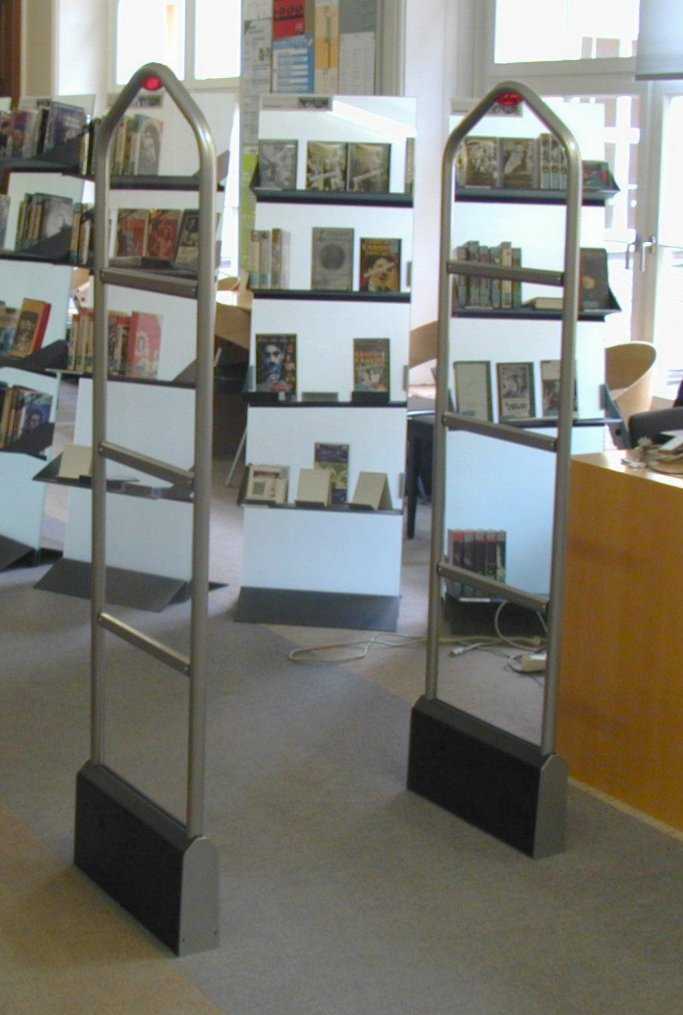
User Manual for Andromeda, RFID Gate Sensor Bibliotheca RFID Library Systems AG, CH-6315 Oberägeri, Switzerlandads100-user.doc Page 1 of 6 FCC WARNING This equipment generates, uses, and can radiate radio frequency energy and if not installed and used in accordance with the instructions, may cause interfer- ence to radio communications. This equipment has been tested and found to comply with Part 15 of the FCC rules: FCC ID: Q3L-ADS100 This device complies with Part 15 of the FCC Rules. Operation is subject to the following two conditions: (1) this device may not cause harmful interference, and (2) this device must accept any interference received, including interference that may cause undesired operation. Unauthorized modifications may void the authority granted under Federal Com- munications Commission Rules permitting the operation of this device User Manual for Andromeda, RFID Gate Sensor Bibliotheca RFID Library Systems AG, CH-6315 Oberägeri, Switzerlandads100-user.doc Page 2 of 6 1.0 Sensor Gate The sensor gate was developed to read information from RFID-labels and cards, which are carried through a passageway. The area that is covered by this function is between the antennas from knee to shoulder height of an average height person. Fig. 2 Library Gate 2.0 Function and technical specifications Through the scanning of data, an alarm (acoustic or optical) or the initiation of other equipment can be triggered. By using a Gate-Tracking-Software, the num- ber and kind of misappropriated media will be registered and can be used for other statistical purposes or to order new items. Fig. 1 Sensor Gate (Win- terthur, Switzerland) User Manual for Andromeda, RFID Gate Sensor Bibliotheca RFID Library Systems AG, CH-6315 Oberägeri, Switzerlandads100-user.doc Page 3 of 6 Basically, certain guidelines must be followed during the installation and usage phases. Usually a site inspection takes place prior to installation, where the posi- tioning and cabling logistics are determined. Despite this, certain preparatory steps can be taken in advance to better facilitate installation and start-up. NOTE: It is important that the gate sensor is positioned in the vicinity of a well- observed area (such as the librarian’s desk) to facilitate a better view over those persons who have triggered an alarm. 2.1 Technical specifications The gate width between the two antennas, center to center is 90 cm. The anten- nas of the gate sensor are connected to a separate reader module. Please refer to the reader module manual for further details. The reader module is equipped with a binary input/output signal used for the op- tical and acoustic signals. Each active antenna is equipped with a light and a buzzer/horn to emit these signals. 3.0 Installation Recommendations Consideration of the following construction tips can assist in achieving optimal functionality of the gate sensor. There are a few illustrations attached with regard to the installation: 1. The equipment should be installed in a "freestanding" way; i.e. there should not be large metal objects within a radius of 3 ½ feet. In order to achieve the desired mechanical stability of the equipment, a firm anchoring method should be chosen. Care should be taken not to damage existing in- frastructure under the floor such as pipes, cables and reinforcements. Electrical connections to existing infrastructure under the floor should be avoided. If the antennas are delivered with a base structure, then the base should be screwed to the antennae. In this case, drilling into the floor is not necessary. 2. Construction of the equipment on surfaces where heating systems are lo- cated under the floor must be cleared with Bibliotheca first. User Manual for Andromeda, RFID Gate Sensor Bibliotheca RFID Library Systems AG, CH-6315 Oberägeri, Switzerlandads100-user.doc Page 4 of 6 3. Connections, such as data communication cables, etc. should be perpen- dicular to the gate sensor direction. The cables have to lead directly away from the antennas without loops or angles. 4. If there are heavy industrial power-lines/systems located in the same building, an equipment test should be performed in the planned installation area prior to installation. 5. Walls with metal structures can affect the antennas. Steel girders, struc- tural steel, metallic water pipes, metallic heater pipes and lightning protec- tion systems are, depending upon their location, surrounded by high fre- quency electromagnetic fields, which can lead to disturbances. A spatial distance of 7 feet from such elements is therefore necessary. 6. Television sets personal computers and accessories, as well as short wave receivers should not be operated within 7 feet of the gate sensor. 7. A distance of 7 feet from fluorescent lamps and 15 feet from fluorescent tubes should be maintained as they may also lead to disturbances. 8. Mechanical devices such as household appliances, electric power tools and electric toys can also cause interference. The distance from such devices must be at least 7 feet. 9. Other RFID-systems, which operate using the same frequency range, can cause interference. To avoid this, a distance of 10 feet should be observed. User Manual for Andromeda, RFID Gate Sensor Bibliotheca RFID Library Systems AG, CH-6315 Oberägeri, Switzerlandads100-user.doc Page 5 of 6 Fig. 3 Top View for installing and cabling the antennas User Manual for Andromeda, RFID Gate Sensor Bibliotheca RFID Library Systems AG, CH-6315 Oberägeri, Switzerlandads100-user.doc Page 6 of 6 NOTE: If two gate sensors are set up within 8 m of one another, the respective antennas must be synchronized. To facilitate this, a cable (2x2x0,22 mm 2 shielded and paired, such as Unitronic (LiYCY (TP) Æ ca. 7,0 mm) needs to be in- stalled. Data transfer If data stored from the gate sensor process needs to be analyzed the standard and present interface of the scanner module can be used. In order to transfer the data, a PC with the appropriate software …

Text truncated - open the document above for the full version.

Cover Letter(s)

LUCATRON AGCH-8606 Greifensee Stationsstrasse 10Switzerland Article Security and IdentificationPhone +41 1 905 20 70Fax +41 1 905 20 75 CONFIDENTIALITY REQUEST Federal Communications CommissionOctober 3, 2003 Authorization and Evaluation Division 7435 Oakland Mills Road Columbia, MD 21046 Re: Bibliotheca RFID Library Systems AG application for certification of a Low Power Communications Device; FCC ID: Q3L-ADS100 Gentlemen: Bibliotheca RFID Library Systems AG herein submits an Application for Equipment Authorization to be followed by submission of a fee for $1190.00 along with Form 159 for certification of a low power communications transmitter under FCC Rules Part 15 as required by the FCC Rules. Bibliotheca RFID Library Systems AG requests, pursuant to 47CFR 0.459, post grant confidentiality for portions of the material contained in this application such that the identified material will be withheld from public inspection following the grant of this authorization. This material, as indicated by request for confidentiality of the item during the electronic submission process and further identified below, includes: 1. Schematics 2. Parts List 3. Block Diagram 4. Operational Description 5. Internal Photos Specifically, these exhibits contain information relating to circuit function and complexity that could be of benefit to competitors. The material contains trade secrets and confidential information that Bibliotheca RFID Library Systems AG does not customarily release to the public and which is otherwise not generally available to the public. Please contact the undersigned by phone at +411-905-2070, by fax at +411-9052075, by email at [email protected], or by correspondence at the address below if there are any further questions or additional information needed concerning this filing. Regards, Signature Philipp MĂĽller Lucatron AG Stationsstrasse 10 CH8606 Greifensee Switzerland

Cover Letter(s)

LUCATRON AGCH-8606 Greifensee Stationsstrasse 10Switzerland Article Security and IdentificationPhone +41 1 905 20 70Fax +41 1 905 20 75 CONFIDENTIALITY REQUEST Federal Communications CommissionOctober 3, 2003 Authorization and Evaluation Division 7435 Oakland Mills Road Columbia, MD 21046 Re: Bibliotheca RFID Library Systems AG application for certification of a Low Power Communications Device; FCC ID: Q3L-ADS100 Gentlemen: Bibliotheca RFID Library Systems AG herein submits an Application for Equipment Authorization to be followed by submission of a fee for $1190.00 along with Form 159 for certification of a low power communications transmitter under FCC Rules Part 15 as required by the FCC Rules. Bibliotheca RFID Library Systems AG requests, pursuant to 47CFR 0.459, post grant confidentiality for portions of the material contained in this application such that the identified material will be withheld from public inspection following the grant of this authorization. This material, as indicated by request for confidentiality of the item during the electronic submission process and further identified below, includes: 1. Schematics 2. Parts List 3. Block Diagram 4. Operational Description Specifically, these exhibits contain information relating to circuit function and complexity that could be of benefit to competitors. The material contains trade secrets and confidential information that Bibliotheca RFID Library Systems AG does not customarily release to the public and which is otherwise not generally available to the public. Please contact the undersigned by phone at +411-905-2070, by fax at +411-9052075, by email at [email protected], or by correspondence at the address below if there are any further questions or additional information needed concerning this filing. Regards, Signature Philipp MĂĽller Lucatron AG Stationsstrasse 10 CH8606 Greifensee Switzerland

ID Label/Location Info

FCC ID: Q3L-ADS100 CH-6315 Oberägeri Switzerland RFID Gate ADS-100 S/N 021001 This device complies with Part 15 of the FCC Rules. Operation is subject to the following two conditions: (1) this device may not cause harmful interference, and (2) this device must accept any interference received, including interference that may cause undesired operation.

Parts List/Tune Up Info

RFID-Aquila System Tuning Guide R R F F I I D D T T u u n n i i n n g g G G u u i i d d e e A A q q u u i i l l a a - - S S y y s s t t e e m m LUCATRON AG CH-8606 Greifensee, Switzerland Version 1.1 Page 1 RFID-Aquila System Tuning Guide Table of Contents Page 1. Installation...................................................................................................................................3 2. Detection Rate with a CD-Label (label on CD)...........................................................................3 3. Preparation..................................................................................................................................3 3.1. Required Tools.....................................................................................................................3 3.2. System Preparation..............................................................................................................3 3.2.1. Presetting Passive Antenna.......................................................................................4 3.2.2. Presetting Active Antenna.........................................................................................4 3.3. Network Analyzer Preparation..............................................................................................4 4. Tuning..........................................................................................................................................5 4.1. Pre-Tuning...........................................................................................................................5 4.2. Fine-Tuning Aquila Active Antenna.......................................................................................5 4.3. Fine Tuning Passive Antenna...............................................................................................6 5. System Test.................................................................................................................................6 6. MAB Active Antenna Schematic.................................................................................................7 6.1. MAB Passive Antenna Schematic........................................................................................7 7. MAB Active Antenna Layout.......................................................................................................8 7.1. MAB Passive Antenna Layout..............................................................................................8 LUCATRON AG CH-8606 Greifensee, Switzerland Version 1.1 Page 2 RFID-Aquila System Tuning Guide 1. Installation Reference installation layout for a library with CD-Labels 85cm Active Antenna Passive Antenna Long Range Reader CoaxialCable(RG58) , max.8mmin.6m Important: The coax cable MUST have a length of minimum 6 meters. 2. Detection Rate with a CD-Label (label on CD) Facts: - Aisle width 85 cm - Reader output power 6 watts - Reference CD Detection rate: - Side position 90-95% - Front position 50% - Flat position 10% 3. Preparation 3.1. Required Tools - Network Analyzer (HP 8712ET), must be calibrated - Program file “RFID_Ant.sta” (date 08.08.2002) 3.2. System Preparation - Prepare the system (1 x passive + 1 x active antenna) with an aisle width of 85 cm - Disconnect antenna wiring on passive antenna (X3) LUCATRON AG CH-8606 Greifensee, Switzerland Version 1.1 Page 3 RFID-Aquila System Tuning Guide 3.2.1. Presetting Passive Antenna - Insert jumpers, J6 = IN and J7 = IN (33 pf + 33 pf). Details see schematic - Set C10 and C11 to minimum capacity 3.2.2. Presetting Active Antenna - Insert jumpers, J6 = IN and J7 = IN (33 pf + 33 pf). Details see schematic - Insert jumper J1 = IN (buzzer) and J3 = IN (33 pf) - Set C10, C11 and C2 to minimum capacity - Connect coax cable (min. 6m) to Matching Active Board (MBA) and to the Network Analyzer 3.3. Network Analyzer Preparation - Start program, recall from diskette ”RFID_ANT.sta” - Press buttons “Display and (Data and Memory)” on Network Analyzer - (Calibrate Network Analyzer with the current coax cable) The initial diagram could look like the diagram below (figure 1). Figure1, Initial Diagram LUCATRON AG CH-8606 Greifensee, Switzerland Version 1.1 Page 4 RFID-Aquila System Tuning Guide 4. Tuning 4.1. Pre-Tuning - Turn C10 and C11 to 1/3 of the capacity - Turn C2 to approx. xx Ω (resistive) o * e.g. 85 cm aisle width, active + passive antenna = 22 Ω o e.g. 85 cm aisle width, only active antenna = 50 Ω This value varies if the distance between the antennas changes. 4.2. Fine-Tuning Aquila Active Antenna - Turn on all three (3) trimmers until a similar diagram (fig. 2) is reached (C10 and C11 should have more or less the same capacity, symmetrical). Figure 2, Active Antenna LUCATRON AG CH-8606 Greifensee, Switzerland Version 1.1 Page 5 RFID-Aquila System Tuning Guide 4.3. Fine Tuning Passive Antenna - Reconnect antenna wire into X3 - Turn on C10 and C11 symmetrical until the curve looks like the diagram in figure 3 Important: The resistance must be 50 +/- 3 Ω Figure 3, Final Diagram 5. System Test - Connect the coax cable to the long range reader - Take a reference CD and test detection (see detection rate) LUCATRON AG CH-8606 Greifensee, Switzerland Version 1.1 Page 6 RFID-Aquila System Tuning Guide 6. MAB Active Antenna Schematic 33pf 33pf 33pf 33pf 33pf 33pf J7 J6 J8J9 J5J4 C10 C11 X3 J3 C2 J1 J2 Antenna Light BNC 33pf MAB Active Antenna Schematic 6.1. MAB Passive Antenna Schematic 33pf 33pf 33pf 33pf 33pf 33pf J7 J6 J8J9 J5J4 C10 C11 X3 MAB Passive Antenna Schematic LUCATRON AG CH-8606 Greifensee, Switzerland Version 1.1 Page 7 RFID-Aquila System Tuning Guide LUCATRON AG CH-8606 Greifensee, Switzerland Version 1.1 Page 8 7. MAB Active Antenna Layout J7 J8 J9 J6 J5 J4 C10C11 X3 J1 J2 C2 J3 X1 MAB Active Antenna Layout 7.1. MAB Passive Antenna Layout J7 J8 J9 J6 J5 J4 C10C11 X3 MAB Passive Antenna Layout

Test Report

Test laboratory accredited by metas, the Swiss Federal Office of Metrology and Accreditation Laboratoire d'essai accrédité par metas, l'Office fédéral de métrologie et d'accréditation Prüflabor akkreditiert durch metas, das Bundesamt für Metrologie und Akkreditierung Registration number Numéro d'accréditation : Akkreditierungsnummer STS 024 Schweizerischer Prüfstellendienst Service suisse d'essai Servizio di prova in svizzera Swiss testing service Report no: Rapport no: 13'322 Bericht Nr: Title: Titre: Titel: Radiocom-measurements on LRS-100 / RFID 13.56 according to ETSI EN 300 330-1 and FCC 15 sub. C Date of test: Date de l'essai: March 6th, 2003 Prüfdatum: Customer: Client: LUCATRON AG Kunde: Test place: Lieu de l'essai: Prüfort: montena emc sa CH-1728 Rossens Test performed by Essai effectué par : Prüfer Test report prepared by Rapport d’essai préparé par : Berichterstatter Test report controlled and approved by Rapport d’essai contrôlé et approuvé par : Prüfbescheinigung Mr M. Portmann Mr M. Portmann Mr E. Staub ........................ ........................ Rossens, .................... (Issue Date / Date d'édition / Ausstelldatum) V0116 Main language / Langue principale / Hauptsprache: english / français / deutsch This report may be reproduced in full, partial reproduction may be made only with the written consent of montena emc sa. The present document results from tests on a specimen and does not prejudge to the conformity of all the manufactured products. Ce rapport d’essai peut être reproduit en entier, une reproduction partielle ne peut être faite qu’avec l’autorisation écrite de montena emc sa. Le présent document résulte d'essais sur un spécimen. Il ne préjuge pas de la conformité de l'ensemble des produits fabriqués à l'objet essayé. Dieser Prüfbericht darf nur als Ganzes vervielfältigt werden. Auszüge dürfen nur mit schriftlicher Genehmigung von montena emc sa reproduziert werden. Dieser Bericht beinhaltet die Prüfergebnisse eines Mustergerätes. Es kann daraus nicht auf die Übereinstimmung der Seriegeräte mit dem Mustergerät geschlossen werden. q:\mandats\20025427_lucatron_rfid13_56\lucatron_rapp_radio_13322.doc No. / No. / Nr. : 13'322 Date/Date/Datum : March 6th, 2003 Page/Page/Seite 2 / 19 montena emc sa CH-1728 Rossens - phone ++41 (0)26/411 93 33 - fax ++41 (0)26/411 93 30 - http://www.montena.com Contents / Table des matières / Inhaltsverzeichnis Page/Page/Seite 1. Summary of test results / Résumé des résultats d'essais / Zusammenfassung der Prüfergebnisse.................................................................................................................... 3 2. Applied standards / Normes appliquées / Verwendete Normen......................................... 3 3. Client / Client / Kunde .........................................................................................................4 4. Equipment under test / Equipement à l'essai / Prüfling ...................................................... 4 5. Persons present / Personnes présentes / Anwesende Personen ...................................... 5 6. Function of the EUT ............................................................................................................5 7. Definitions, classifications and test conditions.................................................................... 5 H-FIELD STRENGTH................................................................................................................. 7 TRANSMITTER SPURIOUS EMISSIONS RADIATED (<30 MHz) AT 10 M ............................. 10 FCC - Measurement of the magnetic field 9 kHz - 30 MHz........................................................ 14 Photographs ............................................................................................................................... 19 Total number of pages Nombre total de pages du rapport: Total Anzahl Seiten 19 No. / No. / Nr. : 13'322 Date/Date/Datum : March 6th, 2003 Page/Page/Seite 3 / 19 montena emc sa CH-1728 Rossens - phone ++41 (0)26/411 93 33 - fax ++41 (0)26/411 93 30 - http://www.montena.com 1. Summary of test results / Résumé des résultats d'essais / Zusammenfassung der Prüfergebnisse ETSI EN 300 330-1 Results Transmitter parameters Radiated H-field (carrier) Chap. 7.2.1.2 Passed RF carrier current Not applicable --- Radiated E-field (carrier) Not applicable --- Frequency range of the modulation bandwidth Chap. 7.3 (normal test conditions) Passed Frequency range of the modulation bandwidth Chap. 7.3 (extrem test conditions) Not performed Spurios emissions conducted ( 30 MHz) Not applicable --- Spurios emissions conducted ( 30 MHz) Not applicable --- Spurios emissions radiated ( 30 MHz) Chap. 7.4.3 Passed Spurios emissions radiated ( 30 MHz) Chap. 7.4.4 Not performed Duty cycle Chap. 7.5 Passed Receiver parameters Adjacent channel selectivity – in band Not applicable --- Blocking or desentizitation Not applicable --- Spurious radiations Not applicable --- CFR 47 Part 15 Subpart C Results Conducted emissions Chap. 15.207 Not performed Radiated emissions (f  30 MHz) Chap. 15.209 Passed Radiated emissions (f  30 MHz) Chap. 15.209 Not performed Carrier analysis Chap. 15.225 (normal test conditions) Passed Carrier analysis Chap. 15.225 (extrem test conditions) Not performed 2. Applied standards / Normes appliquées / Verwendete Normen ETSI EN 300 330-1 Electromagnetic compatibility and Radio spectrum Matters (ERM); Short Range Devices (SRD); Radio equipment in the frequency range 9 kHz to 25 MHz and inductive loop systems in the frequency range 9 kHz to 30 MHz; Part 1: Technical characteristics and test methods CFR 47 Part 15 Subpart C Code of Federal Regulations - Telecommunication, Part 15, Subpart C: "Intentional Radiators" No. / No. / Nr. : 13'322 Date/Date/Datum : March 6th, 2003 Page/Page/Seite 4 / 19 montena emc sa CH-1728 Rossens - phone ++41 (0)26/411 93 33 - fax ++41 (0)26/411 93 30 - http://www.montena.com 3. Client / Client / Kunde Cli…

Text truncated - open the document above for the full version.

Test Report

CETECOM ICT Services GmbH Radio Satellite Communication UntertĂĽrkheimer StraĂźe 6-10 . D-66117 SaarbrĂĽckenTelefon: +49 (0)681 598-9100Telefax: -9075 RSC11issue test report consist of24 PagesPage 1 (24) Test report no.: 2_2356-B/00 FCC Rule 15.225 ID ISC.LRM200 Akkreditiertes PrĂĽflaboratorium DAR-Registriernummer: TTI-P-G 166/98 CETECOM ICT Services GmbH Test report no.: 2_2356-B/00Issue Date: 14.12.2000Page 2 (24) Table of Contents 1 General information 1.1 Notes 1.2 Testing laboratory 1.3 Details of applicant 1.4 Application details 1.5 Test item 1.6 Test standards 2 Technical test 2.1 Summary of test results 2.2 Test report 1 General information 1.1 Notes The test results of this test report relate exclusively to the test item specified in 1.5. The CETECOM ICT Services GmbH does not assume responsibility for any conclusions and generalisations drawn from the test results with regard to other specimens or samples of the type of the equipment represented by the test item. The test report may only be reproduced or published in full. Reproduction or publication of extracts from the report requires the prior written approval of the CETECOM ICT Services GmbH. CETECOM ICT Services GmbH Test report no.: 2_2356-B/00Issue Date: 14.12.2000Page 3 (24) 1.2Testing laboratory CETECOM ICT Services GmbH 66117 SaarbrĂĽcken UntertĂĽrkheimer StraĂźe 6 - 10 Deutschland Telefone: + 49 681 598 - 8411 Telefax : + 49 681 598 - 9075 E-mail: [email protected] Internet: www.cetecom.de Accredited testing laboratory DAR-registration number : TTI-P-G-166/98 1.3Details of applicant Name : FEIG ELECTRONIC GmbH Street : Lange StraĂźe 4 City : D-35781 Weilburg-Waldhausen Country : Germany Telephone: +49 (0)6471 / 3109-0 Telefax : +49 (0)6471 / 3109-99 Contact : Mr. Elmar Reichwein Telephone: +49 (0)6471 / 3109-38 1.4Application details Date of receipt of application : 08.12.00 Date of receipt of test item : 12.12.00 Date of test: 12.12.00 1.5Test item Type of equipment : Transponder system Type designation: ID ISC.LRM200 Manufacturer: Street: City: Country: Serial number: Additional informations:: Frequency : 13,56 MHz / 00H0NON Number of channels : 1 Antenna: Inductive loop antenna Power supply: 24V DC / 1,4 A ext. Type of equipment : Carrier power: 0,62 mW ERP / 0,90 mW EIRP 1.6Test standards: FCC Rule Part 15.225 CETECOM ICT Services GmbH Test report no.: 2_2356-B/00Issue Date: 14.12.2000Page 4 (24) 2 Technical test 2.1Summary of test results No deviations from the technical specification(s) were ascertained in the course of the tests performed. Technical responsibility for area of testing : 23.12.99RSC8411Berg M. DateSectionNameSignature 23.12.99RSC8414Ames H. DateSectionNameSignature CETECOM ICT Services GmbH Test report no.: 2_2356-B/00Issue Date: 14.12.2000Page 5 (24) 2.2Test report TEST REPORT FCC Rule Part 15.225 Test report no. : 2_2356-B/00 CETECOM ICT Services GmbH Test report no.: 2_2356-B/00Issue Date: 14.12.2000Page 6 (24) TEST REPORT REFERENCE LIST OF MEASUREMENTS SUBCLAUSEPARAMETER TO BE MEASUREDPAGE Transmitter parameters § 15.225 (a)Field strength of fundamental7 § 15.209Emissions radiated outside of the specified frequency bands8 Band edge compliance § 15.225 (c)Frequency tolerance11 § 15.207 Conducted limits 13 Test equipment listing 14 Photographs of the equipment 16 CETECOM ICT Services GmbH Test report no.: 2_2356-B/00Issue Date: 14.12.2000Page 7 (24) Equipment under test : ID ISC.LRM200 Ambient temperature: 23°C Relative humidity : 37% REFERENCE NUMBER(S) OF TEST EQUIPMENT USED (for reference numbers see test equipment listing) 42 , 65 FIELD STRENGTH OF FUNDAMENTIAL SUBCLAUSE § 15.225 (a) Polarisation of the measurements for the larger power level .: vertical Measurement distance 30 m TEST CONDITIONSFIELD STRENGTH (ÎĽV/m ) Frequency (MHz)13,56 T nom ( 23 )°C V nom ( 24.0 )V QP: 5902 ÎĽV/m 75.42 dBÎĽV/m Maximum deviation from output power under extreme test conditions (dBc) -0,18 Measurement uncertainty±3dB Limits SUBCLAUSE § 15.225 (a) Frequency (MHz)Field strength (ÎĽV/m)Measurement distance (m) 13,5610,000 80 dBÎĽV/m 30 CETECOM ICT Services GmbH Test report no.: 2_2356-B/00Issue Date: 14.12.2000Page 8 (24) Equipment under test : ID ISC.LRM200 Ambient temperature: 23°C Relative humidity : 37% REFERENCE NUMBER(S) OF TEST EQUIPMENT USED (for reference numbers see test equipment listing) 17 - 24 EMISSIONS RADIATEDSUBCLAUSE §15.209 Transmitter operatingModulated/Unmodulated* *(Delete whichever is inappropriate) Measurement distance see table SPURIOUS EMISSIONS LEVEL (ÎĽV/m) 13,56 MHz f (MHz) DetectorLevel (ÎĽV/m) f (MHz) DetectorLevel (ÎĽV/m) f (MHz) DetectorLevel (ÎĽV/m) 33,9QP79,43250,28QP41,21 54,46QP37,58950,2QP94,41 95,08QP41,21 108,5QP78,52 122,0QP75,86 129,37QP48,42 149,08QP34,67 176,89QP33,50 190,35QP43,65 196,97QP36,73 Measurement uncertainty± 3dB Limits SUBCLAUSE § 15.209 Frequency (MHz)Field strength (ÎĽV/m)Measurement distance (m) 0.009 - 0.4902400/F(kHz)300 0.490 - 1.70524000/F(kHz)30 1.705 - 30.03030 30 - 881003 88 - 2161503 216 - 9602003 above 9605003 CETECOM ICT Services GmbH Test report no.: 2_2356-B/00Issue Date: 14.12.2000Page 9 (24) Equipment under test : ID ISC.LRM200 Ambient temperature: 23°C Relative humidity : 37% REFERENCE NUMBER(S) OF TEST EQUIPMENT USED (for reference numbers see test equipment listing) 17 - 24 EMISSIONS RADIATEDSUBCLAUSE §15.209 PEAK QUASI-PEAK FREQUENCY [MHz] EMISSION LEVEL[dBuV/m] 3010010004000 20 40 60 80 100 FCC Part 15 FEIG ID ISC.LR200 7 Dec 2000 14:21:21CETECOM ICT SERVICES GMBH FCC Part 15.209 hp hp CETECOM ICT Services GmbH Test report no.: 2_2356-B/00Issue Date: 14.12.2000Page 10 (24) Equipment under test : ID ISC.LRM200 Ambient temperature: 23°C Relative humidity : 37% REFERENCE NUMBER(S) OF TEST EQUIPMENT USED (for reference numbers see test equipment listing) 64 Band-edge complianceSUBCLAUSE §15.209 SWT 20 s A RF Att 30 dB -41 dB Offset-41 dB Offset Ref Lvl 78 dB ĂŠ V Ref Lvl 78 dB ĂŠ VUnitdB ĂŠ V 6.25 kHz/Center13.56 MHzSpan62.5 kHz RBW 1 kHz VBW 3…

Text truncated - open the document above for the full version.

Contact Information

Applicant

Philipp E Mueller(Head of R&D)
[email protected]411-905-2070Fax: 411-905-2075

Test Firm

Electrosuisse Montena EMCChristophe Perrenoud
[email protected]41-26-411-93-33Fax: 41-26-411-93-30

Technical Specifications

#Rule PartsFrequency RangePower Output
115C13.56 MHz - 13.56 MHz-
Confidentiality
Long Term

Other Applications from Bibliotheca RFID Library Systems AG
TAG reader system - FCC ID Q3L-Q10600 - Bibliotheca RFID Library Systems AG
Q3L-Q10600

TAG reader system

Oct 07, 2004

Equipment Class

DXX - Part 15 Low Power Communication Device Transmitter