Q3O-NC800-GW223R1Motorola Cellular Gateway
Flextronics Sales & Marketing (A-P) Ltd.
Click to zoom
Application Details
- Equipment Class
- PCB - PCS Licensed Transmitter
- Date of Grant
- Mar 28, 2006
- Application Purpose
- Original Equipment
- Date of Application
- Mar 28, 2006
- Equipment Note
- Motorola Cellular Gateway
- Frequency Range
- 1850.00000000 - 1910.00000000
- Country
- Mauritius
Documents & Files
Document Text
Text extracted from the exhibit documents filed with the FCC. Open a document above to read the original.
Users Manual
Motorola Cellular Gateway NC800 User Guide Version 2.0 WARNING: TO PREVENT FIRE OR SHOCK HAZARD, DO NOT EXPOSE THIS PRODUCT TO RAIN OR MOISTURE. THE UNIT MUST NOT BE EXPOSED TO DRIPPING OR SPLASHING. DO NOT PLACE OBJECTS FILLED WITH LIQUIDS, SUCH AS VASES, ON THE UNIT. CAUTION: DO NOT CONNECT THE PLUG INTO AN EXTENSION CORD, RECEPTACLE, OR OTHER OUTLET UNLESS THE PLUG CAN BE FULLY INSERTED WITH NO PART OF THE BLADES EXPOSED. CAUTION: TO ENSURE REGULATORY AND SAFETY COMPLIANCE, USE ONLY THE PROVIDED POWER AND INTERFACE CABLES. CAUTION: TO ENSURE REGULATORY AND SAFETY COMPLIANCE, USE ONLY THE PROVIDED EXTERNAL ANTENNA. CAUTION: DO NOT OPEN THE UNIT. DO NOT PERFORM ANY SERVICING OTHER THAN THAT CONTAINED IN THE INSTALLATION AND TROUBLESHOOTING INSTRUCTIONS. REFER ALL SERVICING TO QUALIFIED SERVICE PERSONNEL. CAUTION: CHANGES AND MODIFICATIONS NOT EXPRESSLY APPROVED BY MOTOROLA FOR COMPLIANCE COULD VOID THE USER’S AUTHORITY TO OPERATE THE EQUIPMENT. CAUTION: EXPOSURE TO RADIO FREQUENCY RADIATION. TO COMPLY WITH THE FCC RF EXPOSURE COMPLIANCE REQUIREMENTS, THE SEPARATION DISTANCE BETWEEN THE ANTENNA AND ANY PERSON’S BODY (INCLUDING HANDS, WRISTS, FEET AND ANKLES) MUST BE AT LEASE 20 CM (8 INCHES). This device complies with Part 15 sub b of the FCC Rules. Operation is subject to the following two conditions: (1) This device may not cause harmful interference, and (2) this device must accept any interference received, including interference that may cause undesired operation. Note: This equipment has been tested and found to comply with the limits for a Class B digital device, pursuant to Part 15 sub b of the FCC Rules. These limits are designed to provide reasonable protection against harmful interference in a residential installation. This equipment generates, uses and can radiate radio frequency energy and, if not installed and used in accordance with the instructions, may cause harmful interference to radio communications. However, there is no guarantee that interference will not occur in a particular installation. If this equipment does cause harmful interference to radio or television reception, which can be determined by turning the equipment off and on, the user is encouraged to try to correct the interference by one or more of the following measures: • Reorient or relocate the receiving antenna of the radio or television. • Increase the separation between the equipment and receiver. • Connect the equipment into an outlet on a circuit different from that to which the receiver is connected. • Consult the dealer or an experienced radio/TV technician for help. This device must be installed and used in strict accordance with the manufacturer’s instructions as described in the user documentation that comes with the product. Postpone Motorola Cellular Gateway NC800 installation until there is no risk of thunderstorm or lightning activity in the area. Do not overload outlets or extension cords, as this can result in a risk of fire or electric shock. Overloaded AC outlets, extension cords, frayed power cords, damaged or cracked wire insulation, and broken plugs are dangerous. They may result in a shock or fire hazard. Route power supply cords so that they are not likely to be walked on or pinched by items placed upon or against them. Pay particular attention to cords where they are attached to plugs and convenience receptacles, and examine the point where they exit from the product. Place this equipment in a location that is close enough to an electrical outlet to accommodate the length of the power cord. Place this equipment on a stable surface. When using this device, basic safety precautions should always be followed to reduce the risk of fire, electric shock and injury to persons, including the following: • Read all of the instructions (listed here and/or in the user manual) before you operate this equipment. Give particular attention to all safety precautions. Retain the instructions for future reference. • Comply with all warning and caution statements in the instructions. Observe all warning and caution symbols that are affixed to this equipment. • Comply with all instructions that accompany this equipment. • Avoid using this product during an electrical storm. There may be a risk of electric shock from lightning. For added protection for this product during a lightning storm, or when it is left unattended and unused for long periods of time, unplug it from the wall outlet. This will prevent damage to the product due to lightning and power surges. • Operate this product only from the type of power source indicated on the product’s marking label. If you are not sure of the type of power supplied to your home, consult your dealer or local power company. • Upon completion of any service or repairs to this products, ask the service technician to perform safety checks to determine that the product is in safe operating condition. It is recommended that the customer install an AC surge protector in the AC outlet to which this device is connected. This is to avoid damaging the equipment by local lightning strikes and other electrical surges. Different types of cord sets may be used for connections to the main supply circuit. Use only a main line cord that complies with all applicable product safety requirements of the country of use. Installation of this product must be in accordance with national wiring codes. Place unit to allow for easy access when disconnecting the power cord/adapter of the device from the AC wall outlet. Wipe the unit with a clean, dry cloth. Never use cleaning fluid or similar chemicals. Do not spray cleaners directly on the unit or use forced air to remove dust. This product was qualified under test conditions that included the use of the supplied cables between system components. To be in compliance with regulations, the user must use these cables and install them properly. Connect the unit to a grounding type AC wall outlet (100-240 V AC) using the standard power cord/a…
Text truncated - open the document above for the full version.
Users Manual
Motorola Cellular Gateway NC800 User Guide Version 2.0 Page 38 of 110 • Gateway Mode – If the device operates in router mode, the WAN interface is enabled and the DHCP Server and Spanning Tree protocols can be enabled. If the device acts as an access point, it offers only wireless and wired LAN connectivity to clients (stations). The WAN interface, the LAN DHCP Server and the Spanning Tree Protocol are automatically disabled. • Wireless LAN Interface – In order to utilize the Motorola Cellular Gateway NC800 wireless functions, select Enabled. If you do not wish to utilize any wireless functions, make sure Disabled is selected. (Note: No other wireless functions will be available unless you enable this setting.) . • WAN Interface – The WAN interface can be enabled or disabled. If the WAN interface is disabled, there is no access to the Internet via the cellular network. (Note: No other WAN functions on subsequent pages will be available unless you enable this setting.) • Firewall – If you do not want the Motorola Cellular Gateway NC800 to filter any packets you can disable the Firewall feature entirely. The Motorola Cellular Gateway NC800 will then allow all packets to travel through it. If the Firewall is enabled you will not be able to ping the Motorola Cellular Gateway NC800’s WAN interface from the Internet – see the note below. You will, however still be able to ping Internet addresses from the LAN or WLAN. It’s a good idea to keep the firewall enabled if you are connecting to the Internet. The firewall makes it difficult for outsiders to detect your network. It prevents outsiders from “ping-ing” your network by blocking all ping requests originating from outside your network. Only those IP addresses and ports that you specify are opened to traffic originating from the Internet. Motorola Cellular Gateway NC800 User Guide Version 2.0 Page 39 of 110 Gateway-> LAN Interface This page is used to configure the LAN settings of the Motorola Cellular Gateway NC800. The default values displayed on this page will generally be sufficient. The purpose of each field is described below to assist you to fill in appropriate values if you have more advanced requirements. • Primary LAN IP Address – You have to assign a unique static IP address to the Motorola Cellular Gateway NC800’s LAN 1 local interface. Being static, this IP address will not dynamically change and will be the default Motorola Cellular Gateway NC800 address for all computers connecting to this Motorola Cellular Gateway NC800 on the LAN 1 interface or WLAN interface. The default IP address for this Motorola Cellular Gateway NC800 is 192.168.1.1. The dotted-decimal notation must be used. The interested reader is referred to the glossary for more detailed information on IP addressing and subnet masks. The LAN 1 interface is the wired Ethernet port on the back panel labeled LAN 1 and is bridged together with the WLAN interface. • Primary LAN Subnet Mask – IP network mask of the Motorola Cellular Gateway NC800 on the LAN 1 interface, e.g. 255.255.255.0. If you are intentionally using a different subnet mask on your local network, enter the appropriate subnet mask. The dotted-decimal notation must be used. The interested reader is referred to the glossary for more detailed information on IP addressing and subnet masks. • DHCP Server o Enable – The Motorola Cellular Gateway NC800 acts as a DHCP server by assigning IP addresses to computers on the local area network. Important: The DHCP server setting should not be enabled if any other DHCP servers have been setup on the LAN network. Motorola Cellular Gateway NC800 User Guide Version 2.0 Page 40 of 110 o Disable – The Motorola Cellular Gateway NC800 does not assign IP addresses to computers on the LAN. Select this setting if another DHCP server already exists on the network or if static IP addresses are assigned. Please note that the Motorola Cellular Gateway NC800 itself must have a statically assigned IP address because it is acting as a gateway to the LAN network, so its IP address must be known and not change. • LAN DHCP (only available if LAN DHCP Server is set to Enabled) o DHCP Starting IP Address – Specifies the start of the address range that the DHCP server will use, e.g. 192.168.1.100. The DHCP server will only assign IP addresses within the Start - End range. IP addresses outside the range are assumed to be static IP addresses and can be used by computers on the network that have a reserved IP address. The maximum number of IP addresses that can be issued is 253. These addresses should fall within the address ranges reserved for private Internets, unless the address range specified here has been assigned to you by IANA. Please refer to the IP address structure entry in the glossary for more detail regarding the allowable ranges. o DHCP Ending IP Address – Specifies the end of the address range that the DHCP server will use, e.g. 192.168.1.150. o Lease Time – Specifies the number of seconds DHCP leases should be valid for. The maximum lease time can be set to 86400 seconds. A short duration (e.g. 1 hour) is recommended if there are more users than addresses. If users need to keep their addresses while the DHCP Server is unavailable, then the duration should be set to longer than a possible DHCP Server outage. If it is desirable to retain IP addresses even when devices are powered down, then the duration should be set longer than any likely period of inactivity. See also the discussion in the section describing the Gateway-> DHCP Leases screen. • Secondary LAN IP Address – You have to assign a unique static IP address to the Motorola Cellular Gateway NC800’s LAN 2 local interface. Being static, this IP address will not change and will be the default Motorola Cellular Gateway NC800 address for all computers connecting to this Motorola Cellular Gateway NC800 on the LAN 2 interface. The default IP address for this Motorola Cellular Gateway NC800 is 192.168.2.1. The dotted-decimal not…
Text truncated - open the document above for the full version.
Users Manual
Motorola Cellular Gateway NC800 User Guide Version 2.0 Page 59 of 110 802.11b/g supports two types of WEP security services: Open System and Shared key. Under open system authentication, any wireless station can connect to the Motorola Cellular Gateway NC800 provided that it knows the SSID of the Motorola Cellular Gateway NC800. If the Motorola Cellular Gateway NC800 is broadcasting this information, then any wireless client can access the Motorola Cellular Gateway NC800. Under Shared Key the Motorola Cellular Gateway NC800 generates a random 128-bit challenge. The station returns the challenge, encrypted with a shared key—a "secret" key configured into both the station and the Motorola Cellular Gateway NC800. The Motorola Cellular Gateway NC800 decrypts the challenge, using a CRC to verify its integrity. If the decrypted frame matches the original challenge, the station is considered authentic. The challenge/response handshake is repeated in the opposite direction for mutual authentication. WEP data encryption is a weaker encryption method than that used by WPA-PSK. Either 64-bit or 128-bit keys can be specified. If either WEP Data Encryption or Shared-Key Authentication is required, one or more WEP encryption keys must be provided. Note that WEP data encryption can be provided even if shared-key authentication is not required and vice versa. • Authentication. - Selects the WEP authentication method. o Open – all stations are granted access. The default value is Open. o Shared Key – stations possessing the WEP key are allowed access. o 802.1X – 802.1X is used to perform authentication using a RADIUS server and WEP key distribution. Warning: 802.1x Authentication method requires RADIUS server configuration. Motorola Cellular Gateway NC800 User Guide Version 2.0 Page 60 of 110 • Network Re-auth interval – The interval in seconds at which the Motorola Cellular Gateway NC800 distributes a new WEP key. This parameter is valid only if WEP Authentication = 802.1X. The default value is 36000. • WEP Encryption o Enabled – data packets are WEP-encrypted. o Disabled – WEP encryption is performed. If WEP Authentication = 802.1X, then WEP Encryption = Enabled. The default is Disabled. • Network Key (1 – 4) – Enter up to four different network keys. Only one is in use as determined by the "Current Network Key” setting. You can choose between 128-bit or 64-bit WEP encryption. Both allow you to specify up to four keys, but only the selected “Current Network Key” is used. If you are using 64-bit WEP encryption, then the key must be exactly 10 hexadecimal or 5 ASCII characters in length. If you are using 128-bit WEP encryption, then the key must be exactly 26 hexadecimal or 13 ASCII characters in length. Valid hexadecimal digits are “0”-“9” and “A”-“F”. This is only valid if WEP authentication is not Open, or WEP encryption is enabled. Default is blank for all keys. Note: When Authentication is set to 802.1X, only Network Keys 2 or 3 can be used. • Current Network Key – The secret key selected for encrypting outbound traffic and/or authenticating clients. Decimal number between 1 and 4. This is only valid if WEP authentication is not Open, or WEP encryption is enabled. Default is 1. Note: When Authentication is set to 802.1X, only Network Keys 2 or 3 can be selected. Warning: The security settings on the WLAN adapters on the workstations or laptops need to be set up to match the security settings on the Motorola Cellular Gateway NC800. The wireless links between the workstations/laptops and the Motorola Cellular Gateway NC800 need to be restarted after the security settings have been changed. Wireless LAN-> WPA Security This page allows you to configure the Motorola Cellular Gateway NC800's WPA Security settings. Warning: The settings on this page become effective only if the Wireless LAN Interface is set to Enable on the Gateway-> Basic Settings page and Authentication is set to Open on the Wireless LAN-> WEP security. The Motorola Cellular Gateway NC800 supports WLAN Protected Access (WPA), WPA2 (an extension of WPA, based on 802.11i) and WPA Pre-Shared Key (WPA-PSK) authentication methods. WPA, WPA2 and WPA-PSK are all more secure than WEP. The encryption methods that can be used are Temporal Key Integrity Protocol (TKIP) or Advanced Encryption Standard (AES) or both. AES is more secure, but is only supported by newer WLAN devices. If the authentication method is WPA-PSK, a pre-shared key is entered into the Cellular Gateway NC800, and an external RADIUS server is not needed. If the authentication method is not WPA-PSK, an external RADIUS server is required to perform authentication and key distribution. Motorola Cellular Gateway NC800 User Guide Version 2.0 Page 61 of 110 • WPA Authentication– Enables or Disables WPA/WPA2 authentication method. • WPA Pre-authentication o Enabled: Allows a WPA2 client to pre-authenticate with the Gateway toward which it is moving, while maintaining a connection to the Gateway it's moving away from. o Disabled: Pre-authentication is disabled. • WPA Encryption o TKIP - Temporal Key Integrity Protocol o AES - Advanced Encryption Standard o TKIP+AES - both enabled • WPA-PSK Authentication o Enabled – Authentication is by possession of a pre-shared key. o Disabled – Authentication requires the use of a higher-layer authentication method supported by a remote authentication server (RADIUS server). • WPA Pre-Shared Key – Sets the WPA Pre-Shared Key (PSK). The key must be between 8 and 63 ASCII characters or 64 hexadecimal digits. Valid hexadecimal digits are “0”-“9” and “A”-“F”. This parameter is valid if WPA PSK Authentication is Enabled. • Network Re-auth Interval – The interval, in seconds, at which the gateway will request the WLAN client to re-authenticate itself. • Network Key Rotation Interval – The interval, in seconds, at which a new group key (GTK) is distributed. A value of 0 means there is no periodic GTK distribution. Warning: The security settings on the WLAN a…
Text truncated - open the document above for the full version.
Users Manual
Motorola Cellular Gateway NC800 User Guide Version 2.0 Page 78 of 110 • WLAN SSID – The SSID being used by the wireless interface. • WLAN Channel – The current wireless LAN channel being used. • WLAN MAC – The MAC address of the WLAN interface. • WAN Link Status – The state of the WAN link. If there is a WAN connection then this will show "Connected". • WAN Link Idle Time – The time that the WAN link was idle i.e. total time PPP connection was idle. • WAN Link Up Time – The time that the WAN link was in a connected state i.e. total time PPP connection is established. • WAN Link Signal Strength – The last read signal strength for the WAN (CDMA) module obtained when the WAN module was not in data mode. • WAN Module ESN – The ESN of the WAN module. • WAN Firmware Version – The version of the WAN firmware currently running on the gateway. • WAN IP Address – The IP address of the WAN interface. • WAN Default Gateway – The IP address of the default Gateway for the current WAN connection. • WAN Subnet Mask – The WAN Subnet Mask. If WAN IP Settings are statically configured, the WAN IP Address, WAN Default Gateway and WAN Subnet Mask fields display the values configured on the WAN->IP Settings page. For dynamic WAN IP settings, the WAN IP Address, WAN Default Gateway and WAN Subnet Mask fields will only get set once the WAN Link is in the Connected state. • WAN DNS Server 1 – The first DNS server IP address. • WAN DNS Server 2 – The second DNS server IP address. • WAN DNS Server 3 – The third DNS server IP address. • DHCP Server Status – The status of the DHCP server (Enabled / Disabled). Special Buttons: Displays the Summarized status Information. Administration-> Support Server Registration This function allows the Motorola Cellular Gateway NC800 to register itself with a remote support server. If an acknowledgement to the HTTP Post message is not received, the Motorola Cellular Gateway NC800 periodically re-sends the message until the acknowledgement is received. The support server registration URL will be provided to you by the Cellular Carrier or ISP if it has not been configured by default on the Motorola Cellular Gateway NC800. Motorola Cellular Gateway NC800 User Guide Version 2.0 Page 79 of 110 • Support Server – The URL of the support server registration script. You should set this to be: http://<IP>/Moto3G/gateway_register.asp where <IP> is the IP address of the server that is running the statistics logging script and Moto3G is the name of the directory on the web server where the script is stored. Maximum of 4095 characters beginning with the string "http://". The Registration Server can be located anywhere on the Internet. • Retry Interval – Period between 60 and 65535 seconds at which the Post message is resent in case of failure. Special Buttons: Initiates the contact with the Support Server Administration-> Firmware Upload You have two options to upgrade the firmware of the Motorola Cellular Gateway NC800: • Use Firmware Upgrade screen in the web-based configuration utility. • Use a TFTP client. See Appendix D for more information on using a TFTP client to upgrade the Motorola Cellular Gateway NC800 firmware. Motorola Cellular Gateway NC800 User Guide Version 2.0 Page 80 of 110 Web-based firmware upload: • OS Firmware Version – Current version of operating system in the Motorola Cellular Gateway NC800. • Firmware Filename – URL of the new firmware image file. Click on the "Browse" button to browse to the image file on your machine. Firmware files are files having a .trx extension – for example linux.trx is a valid firmware filename. Typically, firmware files are roughly 2.5 MB in size, however, this may differ for newer versions of the firmware. Warning: Do NOT interrupt the upload process. Doing so may cause the firmware in the Motorola Cellular Gateway NC800 to become corrupted. If this happens your only option is to use a TFTP client to repair the firmware. See Appendix D for more information on using a TFTP client to upgrade the Motorola Cellular Gateway NC800’s firmware. Special Buttons: Allows the user to browse the local computer file system for a file to upload. Once you have selected a new firmware file to download to the Motorola Cellular Gateway NC800, click on the Upload button. The upload process takes a few minutes to complete. The Motorola Cellular Gateway NC800 will let you know when the upload has completed. After the upload, the Motorola Cellular Gateway NC800 automatically reboots using the new firmware. Motorola Cellular Gateway NC800 User Guide Version 2.0 Page 81 of 110 Administration-> Restore If you want to restore the Motorola Cellular Gateway NC800’s factory default settings you can do this via the Web Configuration utility. • Restore Defaults – When Enabled the Motorola Cellular Gateway NC800 will restart with the Default Settings when the Restart button is pressed. Special Buttons: Click on the button to restart the Motorola Cellular Gateway NC800. If the Restore Defaults parameter is Enabled, the Motorola Cellular Gateway NC800’s defaults are restored. The process will take approximately 10 seconds to complete. Warning: Any settings you have saved will be lost if the default settings are restored. Please note – the Motorola Cellular Gateway NC800’s IP address reverts back to the default of 192.168.1.1 so you will need to point your browser to that address after the restore Motorola Cellular Gateway NC800 User Guide Version 2.0 Page 82 of 110 Diagnostics There are two pages in the Diagnostics category: Diagnostics-> Internet Access This page is used to troubleshoot problems related to Internet Access. Diagnostics-> LAN Access This page is used to troubleshoot problems related to LAN Access. Diagnostics-> Internet Access This page allows the user to debug errors related to CDMA coverage, CDMA network registration and status, establishment of a PPP connection, IP routing, and DNS lookup. • IP Address – Sets the IP address to use for the IP routing diagno…
Text truncated - open the document above for the full version.
ID Label/Location Info
Figure 1: FCCID Location on Bottom Side FCCID Label to Be Applied In This Location Figure 2: FCCID Detail
Internal Photos
Figure 1: Top Side of PCBs As Installed Figure 2: Bottom Side of Main PCB Figure 3: Top Side of Main PCB with Daughter Board Removed Figure 4: Top Side of Daughter Board Figure 5: Top Side of Daught er Board With Shields Removed Figure 6: Bottom Side of Daughter Board
Parts List/Tune Up Info
The CDMA module used in the NC800 gateway is tuned during production testing of the module. Factory automated test fixtures set the power output of the phone to the target level. The power is then re-measured to ensure the target value is met.
Test Report
This report is for the exclusive use of Intertek's Client and is provided pursuant to the agreement between Intertek and its Client. Intertek's responsibility and liability are limited to the terms and conditions of the agreement. Intertek assumes no liability to any party, other than to the Client in accordance with the agreement, for any loss, expense or damage occasioned by the use of this report. Only the Client is authorized to copy or distribute this report and then only in its entirety. Any use of the Intertek name or one of its marks for the sale or advertisement of the tested material, product or service must first be approved in writing by Intertek. The observations and test results in this report are relevant only to the sample tested. This report by itself does not imply that the material, product, or service is or has ever been under an Intertek certification program. TEST REPORT Report Number: 3088284-003 Project Number: 3088284 Evaluation of theResidential Gateway Model Number: NC800 FCC ID: Q3O-NC800-GW223R1 FCC Part 22 Subpart H FCC Part 24 Subpart E For Flextronics Design: South Africa Test Performed by: Test Authorized by: Intertek 731 Enterprise Drive Lexington, KY 40510 Flextronics Design: South Africa 260 Surrey Avenue, Ferndale Randburg, South Africa 2194 Prepared By:_______________________________Date:____1/21/2006________ Jason Centers, Senior Project Engineer Approved By:______________________________Date:____1/21/2006_________ Bryan C. Taylor, EMC Team Leader Intertek 731 Enterprise Drive, Lexington, KY 40510 Telephone: 859-226-1000 Fax: 859-226-1040 Web: www.etlsemko.com 731 Enterprise Drive, Lexington KY 40510 Evaluation For:Flextronics Design: South Africa FCC ID: Q3O-NC800-GW223R1 Model No: NC800 Model Number: NC800 Report Number: 3088284-003 Page 2 of 41 FCC Part 22H and 24E Evaluation TABLE OF CONTENTS 1 JOB DESCRIPTION .......................................................................................................................... 4 1.1 COMPANY INFORMATION............................................................................................................ 4 1.2 TEST SAMPLE INFORMATION....................................................................................................... 4 1.3 SYSTEM SUPPORT EQUIPMENT.................................................................................................... 5 1.4 CABLES USED DURING TESTING................................................................................................. 5 1.5 SYSTEM BLOCK DIAGRAM(S) ...................................................................................................... 6 1.6 MODE(S) OF OPERATION / ENGINEERING JUDGMENTS................................................................ 7 2 EXECUTIVE SUMMARY................................................................................................................. 8 2.1 MODIFICATIONS REQUIRED FOR COMPLIANCE............................................................................ 8 3 TEST FACILITY................................................................................................................................ 9 3.1 TEST EQUIPMENT......................................................................................................................... 9 4 CONDUCTED RF POWER ............................................................................................................ 10 4.1 TEST PROCEDURE...................................................................................................................... 10 4.2 TEST RESULTS........................................................................................................................... 10 5 RADIATED RF POWER ................................................................................................................. 11 5.1 TEST PROCEDURE...................................................................................................................... 11 5.2 TEST RESULTS........................................................................................................................... 12 6 MAXIMUM PERMISSIBLE EXPOSURE (MPE) CALCULATIONS ...................................... 13 6.1 CALCULATIONS.......................................................................................................................... 13 6.2 TEST RESULTS........................................................................................................................... 13 7 EMISSION LIMITATIONS, OCCUPIED BANDWIDTH .......................................................... 14 7.1 TEST PROCEDURE...................................................................................................................... 14 7.2 TEST RESULTS........................................................................................................................... 14 8 OUT OF BAND EMISSION AT ANTENNA TERMINALS........................................................ 21 8.1 TEST PROCEDURE...................................................................................................................... 21 8.2 TEST RESULTS........................................................................................................................... 22 9 FIELD STRENGTH OF SPURIOUS RADIATION .............................…
Text truncated - open the document above for the full version.
Contact Information
Applicant
Loh Boon Liang(Project Manager)
Technical Contact
Flextronics South AfricaWarren Tromp
[email protected]27 11 293 0500
260 Surrey Avenue, Randburg · Pinegowrie · South Africa
Non-Technical Contact
Flextronics South AfricaLukas Stoltz
[email protected]27 11 293 0500
Test Firm
Intertek Testing Services NA Inc.Bryan Taylor
Technical Specifications
| # | Rule Parts | Frequency Range | Power Output | Emission | Tolerance |
|---|---|---|---|---|---|
| 4 | 24E | 1.85 GHz - 1.91 GHz | 322.00 mW | 1M2FXW | 150 Hz |
Other Applications from Flextronics Sales & Marketing (A-P) Ltd.
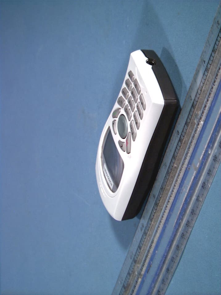
Q3OODM-QB04
Jun 04, 2003Dual-Mode Cellular Phone (AMPS/CDMA)
Equipment Class
TNE - Licensed Non-Broadcast Transmitter Held to Ear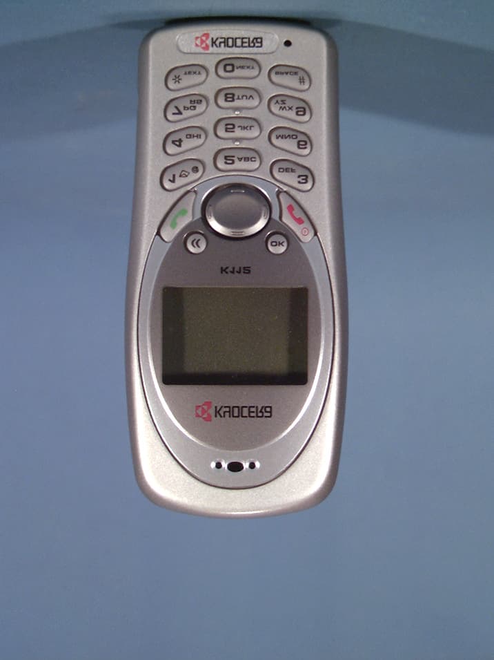
Q3OKWC-K112
May 07, 2003Dual-Mode Cellular Phone (AMPS/CDMA)
Equipment Class
TNE - Licensed Non-Broadcast Transmitter Held to Ear