Q4BMR2KWIRELESS 2000 WATT COMMERCIAL DIMMER
The Watt Stopper, Inc.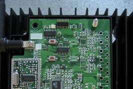
Click to zoom
Application Details
- Equipment Class
- DTS - Digital Transmission System
- Date of Grant
- Oct 19, 2006
- Application Purpose
- Original Equipment
- Date of Application
- Oct 19, 2006
- Equipment Note
- WIRELESS 2000 WATT COMMERCIAL DIMMER
- Frequency Range
- 904.87000000 - 924.88000000
- Company
- The Watt Stopper, Inc.
- Country
- United States
Documents & Files
Document Text
Text extracted from the exhibit documents filed with the FCC. Open a document above to read the original.
Users Manual
REV DESCRIPTION INT: REV. DATE APPROVED 1 ECO# CO1556 MJS 10/9/06 CG 2 ECO# C01973 MJS TITLE BOX PAGE ONLY. DO NOT MAKE FILM • DO NOT PRINT THIS PAGE MATERIAL: White 16lb (60g/m sq) Ink: Black Print Two Sides Final Trim Size: 8.5” (Wide) x 11” (High) IF YOU HAVE ANY QUESTIONS REGARDING SPECIFICATIONS OR REQUIRE ADDITIONAL FILE FORMATTING, PLEASE CONTACT Mary Jo Sowinski. Phone: 408-486-7511 Email: [email protected] All information in this drawing is the property of Watt Stopper/Legrand and cannot be copied or used without the written approval of Watt Stopper/Legrand. Title: MR2000 Installation Instructions SANTA CLARA, CALIFORNIA DRAWN BY PLM ENG QA MARCOM SOWINSKI SCALE 1:1 Drawing #: 06145 Orig. Drawing Date: 6 OCT 06 Revision Date: 10 OCT 06 REV.#: 2 MR2000 Universal Dimmer Installation Instructions SPECIFICATIONS Voltages ............................................... 120VAC/277VAC, 60Hz Output (Load) ................. Powered via Input (Line) to Neutral Maximum Load Rating .......2000W@120VAC, 4432W@277VAC Minimum Load Required ...... 100W@120VAC, 200W@277VAC Load Type Compatibility .......................................................... Note: Burn-in lamps according to manufacturer’s instructions before dimming with the MR2000. The following are limited to 2000W@120VAC max: Incandescent & quartz halogen Electronic low voltage dimming rated transformers Neon/cold cathode dimming rated ballasts The following are limited to 2000W@120VAC or 4432W@277VAC max: Magnetic low voltage transformer Dimming rated 2-wire fluorescent (Advance MarkX or equivalent) Compact fluorescent dimming rated ballasts Required Branch Circuit Overcurrent Protection Ratings: ............................... 120VAC/277 VAC, 20 A, 60 Hz Environment Operating Temperature ...................... 32°-104°F (0°-40°C) Operating Humidity .... Less than 95%RH, non-condensing DESCRIPTION The Miro MR2000 is a high capacity universal dimmer designed for remote mounting in a 4” square box with a 1½” extender. The dimmer is suitable for surface, semi-recess or plenum mounting. Remote user control is available by either binding the MR2000 to a wireless Miro control device such as a wireless multilocation controller (see Figure 1) or by wiring the MR2000 to a Miro multilocation controller through a traveler wire (see Figure 2). The MR2000 is wired directly to the load. It is a forward phase control dimmer with a normally open air-gap relay at the load output. It provides 120/277VAC, phase to neutral input to the load. Top Dog™ Wireless Communication Watt Stopper wireless devices use radio signals to communicate with each other to control lighting and other types of electric loads in selected areas. These wireless devices use the 900MHz band for high-speed control communication. Using Watt Stopper “frequency-agile” Top Dog™ technology, these wireless devices avoid interference with other 900MHz devices, such as cordless phones and baby monitors. Load Types Use the Miro Universal Dimmer for these load types: • Incandescent & quartz halogen lamps. • Dimmable, 2-wire fl uorescent and compact fl uorescent, electronic low voltage, magnetic low voltage, neon or cold cathode. Do not mix different load types on the same dimmer. Do not use with fl uorescent lamps other than those listed. See SPECIFICATIONS. CAUTION Do not install to control a receptacle, or a motor-operated appliance. ENVIRONMENT AND ORIENTATION This product is designed for indoor use only where the ambient temperature in the unit’s vicinity does not exceed 104°F (40°C). Allow space for ventilating 100 BTU/Hr. Unit must be mounted in a 2¹⁄ 8” deep 4” square steel electrical box plus 1½” extension such that the heatsink is spaced 1½” away from the wall in which the 4” square box is mounted. Unit must be oriented such that the heatsink fins run lengthwise vertically to permit natural upward convection whether wall or plenum mounted. Allow a minimum of 6” space above and below the unit and do not block vertical airflow though the heatsink. Call 800-879-8585 for Technical Support www.wattstopper.com Power Miro 2000W Dimmer Scene Controller Multilocation Controller Figure 1 - Miro Wireless Network Application WIRING INSTRUCTIONS 1. Disconnect power to the circuit by turning the circuit breaker OFF before installation. WARNING TURN THE POWER OFF AT THE CIRCUIT BREAKER BEFORE INSTALLING THE DIMMER. 2. Strip existing wire ½” (12.7mm). 3. Wire the LINE (black), NEUTRAL (white) and LOAD lead wires to the supply/load wires per Figure 2. If installing in a grounded metal box, the unit will be grounded to the electrical box. Otherwise, use the green ground screw to connect to ground as shown in Figure 2. Use #12AWG copper wire. Depending on the application and the number of connections, more space may be needed. If so, use an appropriate size box or box extension. 4. If the MR2000 will be controlled by a wired multilocation controller (MCD68/DCD68) connect the yellow traveler wire per the instructions provided with the controller. If using the MR2000 in a Miro wireless network, the yellow traveler wire is not used and must be capped. 5. Switch the circuit breaker back ON. 6. If the unit is to be controlled from a Miro wireless device, refer to “SET HOUSE ID” on the next page. INSTALL IN COMPLIANCE WITH ALL APPLICABLE CODES & STANDARDS. Failure to follow these instructions may cause personal injury or equipment damage. Load Wires Supply Wires Multilocation Controller Traveler (YEL) Ground Neutral (WHT) Line (BLK) Load (RED) Wire Legend GND (Connect to building ground) Max. traveler wire 200' (60m) GND Figure 2 - Wiring Diagram A Miro 2000W Dimmer is compatible with wired Miro devices, as shown above connected by a traveler wire between the MR2000 and the Multilocation Controller (either MCD68 or DCD68). It will also communicate with a wireless Miro network (see Figure 1). Call 800-879-8585 for Technical Support www.wattstopper.com INSTALLATION The unit must be install…
Text truncated - open the document above for the full version.
Cover Letter(s)
Siemic Laboratories Accessing Global Markets 2206 Ringwood Avenue, San Jose, CA 95131, USA, +1(408)526 1188, +1(408)526 1088, [email protected] Timco Engineering, Inc. 849 N.W. State Road 45 P.O. Box 370 Newberry, Florida 32669 USA 20 September 2006 RE: Confidentiality Request Dear Reviewer: This letter is a request for confidentiality for specific exhibits in reference to The Watt Stopper, Inc. filing for Model MR2000 under the FCC ID: Q4B-MR2K. The following exhibits are requested to be held in confidentiality and withheld from public inspection pursuant to 47 CFR 0.457(d): 1. Schematics – MR2000 schematic 1.pdf and MR2000 schematic 2.pdf. 2. Block Diagrams – block diagram.pdf. 3. Operational Description – Operational Description 3.pdf. These exhibits contain details of the proprietary operation of the product. These details are not readily discernible from the hardware, constitute trade secrets, and are not generally accessible by the public. We request that the above documents and this letter be withheld from public inspection. Please contact us if further justification for any of the above exhibits is necessary. Sincerely, Kerwinn Corpuz
External Photos
EUT EXTERNAL PHOTO: Model MR2000 FRONT SIDE BACK SIDE RIGHT SIDE LEFT SIDE TOP SIDE BOTTOM SIDE
ID Label/Location Info
LABEL/LOCATION SAMPLE for Model: MR2000; FCC ID: Q4BMR2K Label on the back side of EUT Zoom into Label
Internal Photos
EUT INTERNAL PHOTO: Model MR2000 RF BOARD TOP SIDE RF BOARD BOTTOM SIDE MAIN BOARD TOP SIDE MAIN BOARD BOTTOM SIDE POWER SUPPLY TOP SIDE POWER SUPPLY BOTTOM SIDE
RF Exposure Info
MPE CALCULATION For Wattstopper, Inc.; Model MR2000; FCCID: Q4BMR2K RF Exposure Requirements: 47 CFR §1.1307(b) RF Radiation Exposure Limits: 47 CFR §1.1310 RF Radiation Exposure Guidelines: FCC OST/OET Bulletin Number 65 EUT Frequency Band: 902 – 928 MHz EUT Maximum Measured Conducted Power: 0 dBm (0.001 Watt) EUT Antenna Gain: 3 dBi (2 numeric) Limits for General Population/Uncontrolled Exposure: f/1500; f (frequency) in MHz Power Density Limit: 902 / 1500 = 0.601 mW/cm 2 or 6.01 W/m 2 Equation: S = PG / 4πR 2 or R = √PG / 4πS Where, S = Power Density P = Power Input to Antenna G = Antenna Gain R = distance to the center of radiated antenna S = 0.001W*2 / 4*3.14*(0.2m) 2 = 0.002W / 0.503m 2 = 0.004 W/m 2 (0.0004 mW/cm 2 ) EUT comply with 20cm distance exposure.
Test Report
TEST REPORT FROM FOR MR2000 (2000 Watt Dimmer) TO 47 CFR 15.247(f):2005 Test Report Serial No.: SL06083001-WAT-001 This report supersedes None Remarks: Equipment complied with the specification [X ] Equipment did not comply with the specification [ ] This Test Report is Issued Under the Authority of: .......................................................................................................... Tested by: Kerwinn Corpuz, Test Engineer .......................................................................................................... Reviewed by: Leslie Bai, Lab Manager Issue date: 19 September 2006 Manufacturer: The Wattstopper, Inc. This test report may be reproduced in full only. NVLAP Lab Code: 200729-0 Registration No. 783147 Registration No. 4842 RTA No. D23/16V Lab Code: KR0032 Title: The Wattstopper, Inc. FCC ID: Q4BMR2K To: 47 CFR 15.247(f):2005 Serial# SL06083001-WAT-001 Issue Date 19 September 2006 Page 2 of 40 www.siemic.com This page has been left blank intentionally. Title: The Wattstopper, Inc. FCC ID: Q4BMR2K To: 47 CFR 15.247(f):2005 Serial# SL06083001-WAT-001 Issue Date 19 September 2006 Page 3 of 40 www.siemic.com CONTENTS EXECUTIVE SUMMARY..............................................................................................................................................5 1 TECHNICAL DETAILS..........................................................................................................................................6 2 TESTS REQUIRED..................................................................................................................................................7 3 ANTENNA REQUIREMENT..................................................................................................................................8 4 MEASUREMENTS, EXAMINATIONS AND DERIVED RESULTS.................................................................9 5 TEST INSTRUMENTATION................................................................................................................................32 APPENDIX A: EUT TEST CONDITIONS.................................................................................................................33 APPENDIX B: EXTERNAL PHOTOS........................................................................................................................34 APPENDIX C: CIRCUIT/BLOCK DIAGRAMS.......................................................................................................35 APPENDIX D: INTERNAL PHOTOS.........................................................................................................................36 APPENDIX E: PRODUCT DESCRIPTION...............................................................................................................37 APPENDIX F: FCC LABEL LOCATION..................................................................................................................38 APPENDIX G: USER MANUAL.................................................................................................................................39 Title: The Wattstopper, Inc. FCC ID: Q4BMR2K To: 47 CFR 15.247(f):2005 Serial# SL06083001-WAT-001 Issue Date 19 September 2006 Page 4 of 40 www.siemic.com This page has been left blank intentionally. Title: The Wattstopper, Inc. FCC ID: Q4BMR2K To: 47 CFR 15.247(f):2005 Serial# SL06083001-WAT-001 Issue Date 19 September 2006 Page 5 of 40 www.siemic.com Executive Summary The purpose of this test programme was to demonstrate compliance of the The Wattstopper, Inc., MR2000 (2000 Watt Dimmer) against the current 47 CFR 15.247(f):2005. The MR2000 demonstrated compliance with the 47 CFR 15.247(f):2005. The Wattstopper, Inc. is the applicant and claimed manufacturer of this tested product. For the detailed description of this product, please refer to the MR2000 User Manual. The equipment under test is a hybrid system operating in the 902-928MHz band. The equipment was tested with the following antenna: Liberal Industrial Limited, Part Number B13915L088808; 3 dBi Dipole antenna The test has demonstrated that this unit complies with stipulated standards. EUT Sample Title: The Wattstopper, Inc. FCC ID: Q4BMR2K To: 47 CFR 15.247(f):2005 Serial# SL06083001-WAT-001 Issue Date 19 September 2006 Page 6 of 40 www.siemic.com 1 Technical Details Purpose Compliance testing of MR2000 with 47 CFR 15.247(f):2005 Applicant / Client The Wattstopper, Inc. 6212 Corte Del Abeto, Suite 200 Carlsbad, CA 92009 Manufacturer The Wattstopper, Inc. Laboratory performing the tests SIEMIC Labs 2206 Ringwood Avenue San Jose, CA 95131 Test location(s) SIEMIC Labs 2206 Ringwood Avenue San Jose, CA 95131 Test report reference number SL06083001-WAT-001 Date EUT received 6 September 2006 Standard applied 47 CFR 15.247(f):2005 Dates of test (from – to) 7 September 2006 to 18 September 2006 No of Units: 1 Equipment Category: DTS Trade/Product Name: MR2000 Type/Model Name/No: MR2000 Technical Variants: MR2000 FCC ID No. Q4BMR2K Title: The Wattstopper, Inc. FCC ID: Q4BMR2K To: 47 CFR 15.247(f):2005 Serial# SL06083001-WAT-001 Issue Date 19 September 2006 Page 7 of 40 www.siemic.com 2 Tests Required The product was tested in accordance with the following specifications. The test results recorded in this Test Report are exclusively referred to the tested sample(s). Test Standard Description Pass / Fail 47 CFR Part 15.247: 2005 RSS 210 Issue6: 2005 15.203 Antenna Requirement Pass 15.205 RSS210(A8.5) Restricted Band of Operation Pass 15.207(a) RSSGen(7.2.2) Conducted Emissions Voltage Pass 15.247(a)(1) RSS210(A8.1) Channel Separation Pass 15.247(a) RSS210(A8.1) Occupied Bandwidth Pass 15.247(a)(1) RSS210(A8.1) Number of Hopping Channels Pass 15.247(a)(1) RSS210(A8.1) Time of Occupancy Pass 15.247(b) RSS210(A8.4) Output Power Pass 15.247(c) RSS210(A8.4) Antenna Gain > 6 dBi N/A 15.247(d) RSS210(A8.5) Conducted Spurious Emissions Pass 15.209; 15.247(d) RSS210(A8.5) Radiated Spurious …
Text truncated - open the document above for the full version.
Test Setup Photos
TEST SETUP PHOTO: MR2000 Conducted Emissions Voltage Setup Radiated Emission setup < 1 GHz Radiated Emission setup > 1 GHz Conducted Measurement setup
Contact Information
Applicant
Sarah Turner(Advanced Compliance Engineer)
Test Firm
SIEMIC LaboratoriesLeslie Bai
Technical Specifications
| # | Rule Parts | Frequency Range | Power Output |
|---|---|---|---|
| 1 | 15C | 904.87 MHz - 924.88 MHz | 1.00 mW |
Other Applications from The Watt Stopper, Inc.
Q4B-ZBSD
Mar 04, 2026ZB Wireless Slim Switch
Equipment Class
DTS - Digital Transmission System
Q4B-P4
Dec 01, 2020BLE and 6LoWPAN Wireless module
Equipment Class
DTS - Digital Transmission System
Q4B-P3B
Oct 13, 2020BLE and 6LoWPAN Wireless module
Equipment Class
DTS - Digital Transmission System
Q4B-EOPC-100
Dec 20, 2012Wireless Self-Powered PIR Ceiling Mount Extented Range Occupancy Sensor
Equipment Class
DSC - Part 15 Security/Remote Control Transmitter
Q4BTDKFOB
Jul 25, 2007TOPDOG KEY FOB SCENE CONTROLLER
Equipment Class
DTS - Digital Transmission System