Q4I1600GPS-ENABLED MODEM
Elutions, Inc.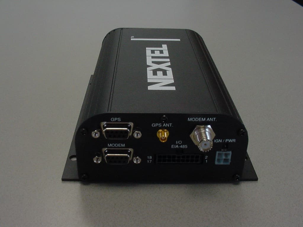
Click to zoom
Application Details
- Equipment Class
- TNB - Licensed Non-Broadcast Station Transmitter
- Date of Grant
- Aug 05, 2004
- Application Purpose
- Original Equipment
- Date of Application
- Aug 05, 2004
- Equipment Note
- GPS-ENABLED MODEM
- Frequency Range
- 896.00000000 - 901.00000000
- Company
- Elutions, Inc.
- Country
- United States
Documents & Files
Document Text
Text extracted from the exhibit documents filed with the FCC. Open a document above to read the original.
Users Manual
iR1600 Rugged Modem iR1600 GPS-Enabled Modem Installation Guide Installation Guide TABLE OF CONTENTS TABLE OF FIGURES ............................................................................................................... ........................................................... 1 FCC COMPLIANCE................................................................................................................. ............................................................ 3 REQUIRED COMPONENTS............................................................................................................ .................................................... 5 Box Contents ................................................................................................................... ................................................................................ 5 Documentation .................................................................................................................. .................................................................................... 6 Required Components for Installation (sold separately) ......................................................................... ........................................................ 6 Components for Mobile Environment (sold separately) ............................................................................ ............................................................ 7 Components for Fixed Environment (sold separately) ............................................................................. ............................................................. 7 Approved Components List ....................................................................................................... ............................................................................ 7 How to Order Components........................................................................................................ .......................................................................... 11 Required Components for Operation.............................................................................................. ................................................................. 9 iDEN Packet Data Applet ............................................................................................................ ........................................................................ 9 Data Account Activation ........................................................................................................ ................................................................................ 9 INTRODUCTION ................................................................................................................... ............................................................ 11 Nextel Coverage ...................................................................................................................... .................................................................... 11 Nextel Customer Care .................................................................................................................. ............................................................... 11 PRODUCT OVERVIEW ............................................................................................................... ...................................................... 13 General Overview ............................................................................................................... ........................................................................... 13 Modem Characteristics .......................................................................................................... ........................................................................ 14 Modem Operating Modes .......................................................................................................... .................................................................... 15 Data Connections ............................................................................................................... ........................................................................... 15 Modem Types .................................................................................................................... ............................................................................ 15 Modem Components ............................................................................................................... ............................................................................ 16 Front Panel Views.............................................................................................................. ................................................................................................... 16 Rear Panel Views ............................................................................................................... .................................................................................................. 17 Modem Technical Specifications ................................................................................................. .................................................................. 18 INSTALLATION PREPARATION ....................................................................................................... ............................................... 21 Before You Start Installing .................................................................................................... ......................................................................... 21 Installation Planning.......................................................................................................... ............................................................................. 21 Planning Mo…
Text truncated - open the document above for the full version.
ID Label/Location Info
CAD Viewer 4.0 - Register at www.guthcad.com eLutions LABEL LOCATION MADE IN USA GPS ANT. MODEM ANT. EIA-485 I/O IGN / PWR MODEM GPS iDEN STATUS DIAGNOSTIC PTT MIC RESET TM GATEWAY NORMAL AVL RTS Tx DTR CTSRxDSR iR1600 GPS-Enabled Modem 12 1817
ID Label/Location Info
eLutions MODEL NUMBER: IMEI: MADE IN USA iR1600 GPS FCC ID: Q4I1600 123456789012345 SERIAL NUMBER: 1234567890 2D bar code SIM ID/SERIAL 12345678901234567890ABCDEFAB MADE IN USA MODEL: 6000-C5-RFM CODE 39 Bar Code Software Version: 0.0 2D Bar Code 2D Bar Code 2D Bar Code 2D Bar Code Part Number: DZ5001EV Kit SN: 1234567890123 Item ID: 1234567 2D bar code 2D Bar Code IMEI: 123456789012345 Serial Number: 123456789 SIM ID: 123456789012345 2D Bar Code 2D Bar Code 2D Bar Code iR1600 GPS - Enabled Modem SIM ID: 123456789012345
Internal Photos
GPS MODULE Motorola i30SX Phone Board
Operational Description
RFM-6000-3015 Rev 1PAGE: 12 OF 235/20/04 eLutions Proprietary Information 3.2.2 Operational Characteristics The modem shall provide the operational characteristics defined in the following paragraphs. 3.2.2.1 Communications 3.2.2.1.1 Normal Data Mode During normal operation, the modem serial interface shall be directly connected to the i30 card. The modem shall provide all i30 circuit switched, and packet data communication features, as described in the Mobile Subscriber DTE./DCE Interface for Data Services. The modem shall operate identically to an i30sx phone tethered through an NKN6544A accessory data cable. The modem shall default to the Normal Data mode unless one of the other modes (Gateway or AVL) has been initialized through the modem’s diagnostic menu. 3.2.2.1.2 Gateway Data Mode The modem shall also be configurable for operation as a gateway device. In this mode, the modem shall receive basic serial data from the user port, encapsulate it into UDP or TCP packets, and send it out over the iDEN packet data network to a pre-defined IP address. Similarly, the modem shall receive appropriately addressed packets from the iDEN network, parse the data, and send it to the user via the serial port. The modem shall also provide a lookup table for translation of Bristol Babcock BSAP addresses into IP addresses in order to seamlessly route BSAP communications traffic over the iDEN packet data network. In addition, the Gateway Data mode shall support the Hayes Compatible AT mode dial command (ATD) as defined in the iO1000 developer’s guide. Gateway data mode initialization shall be accomplished through the modem’s diagnostic menu. Once initialized, the Gateway mode shall become the default, with all settings retained in non-volatile memory. 3.2.2.1.3 Automatic Vehicle Location (AVL) Mode The modem shall also be configurable for operation as an AVL device. In this mode, the modem shall periodically “read” position information from the internal GPS receiver and external I/O interface, encapsulate it into UDP or TCP packets, and send it out over the iDEN packet data network to a pre- defined IP address. Alternately, the modem shall also be capable of receiving appropriately addressed GPS request messages from the iDEN packet data network, and reply with the requested GPS or external I/O information. The modem shall maintain a non-volatile revolving history of this information, providing a “store and forward” capability for periods of iDEN network coverage loss. In future firmware revisions, the modem shall also have the ability to go to “sleep” (drawing minimal current from the vehicle battery), wake itself up after a configurable interval, send its current GPS location, and then go back to “sleep”. AVL mode initialization shall be accomplished through the modem’s diagnostic menu. Once initialized, the AVL mode shall become the default, with all settings retained in non-volatile memory. 3.2.2.1.4 Direct Connect? Voice Communications The modem shall support the use of an external PTT microphone accessory to enable Direct Connect? voice services. The modem shall provide operating power for the external microphone as well as the analog audio and digital data and control signals necessary to support the voice services and to allow RFM-6000-3015 Rev 1PAGE: 13 OF 235/20/04 eLutions Proprietary Information the user to browse and select from the contact listings stored in the modem’s SIM card. Contact listings shall be created or maintained either through one of Nextel’s existing address book administration services, or through direct entry via the PTT mic. Firmware required to support PTT mic shall not be part of the initial release of the iR1600. 3.2.2.1.5 Access Control List The modem shall provide a user configurable access control list (ACL) which shall include both a range and an individual listing of up to 30 IP addresses. Communications to the modem, will be restricted to those IP addresses contained in the ACL. The ACL shall function in Gateway and AVL operating modes only. It shall have no effect on Normal mode operation. 3.2.2.1.6 Encryption The modem shall provide user configurable encryption/ decryption of iDEN network data. This encryption shall employ a standard 128 bit AES algorithm with an eLutions proprietary security protocol. Encryption shall function in Gateway and AVL operating modes only. It shall have no effect on data transmitted or received in Normal mode. 3.2.2.1.7 Over-The-Air Configuration/ Upgrade The modem shall support remote over-the-air (OTA) configuration and firmware upgrade, initiated by a centralized server. Utilization of this feature shall be limited to modems operating in the AVL or Gateway modes, and activated with public IP addresses. Private IP addresses may be utilized if the upgrade server is also on the iDEN network. For modems operating in Normal mode or with inaccessible IP addresses, the modem user may initiate an OTA upgrade connection, to a pre-defined server IP address, by pressing the master reset pushbutton and holding it for 5 seconds. 3.2.2.1.8 RF Characteristics All modem communications shall provide the following RF operational characteristics. Power :600mW typical Frequency Range :Tx 806-825 MHz, Rx 851-870 MHz Channel Spacing25 KHz Channel Access :TDMA Network Protocol :iDEN 3.2.2.2 Power-Up/Down If ignition sense is utilized, the modem shall power-up when the vehicle’s engine is started. The modem microcontroller shall automatically power-up the i30 board and turn over the communications interface to the user serial data connector. When the vehicle’s engine is stopped, the microcontroller shall de- register the i30 and wait approximately 5 seconds before powering down the modem. If ignition sense is externally bypassed, the microcontroller shall power-up the modem immediately upon application of 12V input power. The modem shall power-down immediately upon loss of 12V input power without de-registering from the network. RFM-6000-3015 Rev 1PAG…
Text truncated - open the document above for the full version.
Parts List/Tune Up Info
ELUTIONS INC. REVISED 05/11/2004 RFM-6000-8001 Rev 2 =Non-identical substitute part; NOT FOR PRODUCTION =Quote needed QTYREFERENCE DESIGNATOR DESCRIPTIONPACKAGEVENDOR/VENDOR#FACTORY PART NUMBER DIGI-KEY PART NO.1K COSTEXT COST20K COST EXT COST 2C49,C50CAP, 10 uF, TANT, 35V, 20%7343SMDSPRAGUE / 593D106X0035D2T SPRAGUE / 593D106X9035D2T EL-700-2000-005MOUSER / 74- 593D35V10D 0.2500.5000.2100.420 2C53,C52CAP, 100 uF, TANT, 10V, 10%7343SMDSPRAGUE / 593D107X9010D2TEL-700-2000-006MOUSER / 74- 593D10V100 0.9041.8080.2980.596 1C55CAP, 33 uF, TANT, 6.3V, 20%6032SMDAVX / TAJC336M006 PAN / ECS-T0JC336R OPEN QML EL-700-2000-004PCS1336CT-ND0.2400.2400.1450.145 3C44,C46,C48CAP, 0.01 uF, CER, 50V, X7R, 20%0805SMDAVX / 08055C103MATMA KEMET / C0805C103M5RAC OPEN QML EL-700-2000-002PCC103BNCT-ND0.0160.0480.0070.020 49C1-C14,C16-C21, C23, C24, C27, C28, C29, C31, C34-C40, C42, C43, C45, C47, C51, C56-C66 CAP, 0.1 uF, CER, 50V, X7R, 20%0805SMDAVX / 08055C104MATMA KEMET / C0805C104M5RAC OPEN QML EL-700-2000-003PCC1840CT-ND0.0160.7840.0140.662 1C54CAP, 0.47 F, 5.5V, 20%, SUPER CAPSEE DATA SHEETTHDPAN / EEC-S5R5V474EL-700-2000-049P6974-ND2.8602.8601.4071.407 1C67CAP, 0.47 uF, CER, 50V, X7R, 20%1206SMDAVX / 12065C474MATMA KEMET / C1206C474M5RAC OPEN QML EL-700-2000-052445-1380-1-ND0.1050.1050.1050.105 1C22CAP, 10 pF, CER, NPO, 25V, 20%0805SMDAVX / 08053A100MATMA KEMET / C0805C100M3GAC OPEN QML EL-700-2000-118PCC100CNCT-ND0.0220.0220.0060.006 2C25,C26CAP, 18 pF, CER, NPO, 25V, 20%0805SMDAVX / 08053A180MATMA KEMET / C0805C180M3GAC OPEN QML EL-700-2000-001PCC180CNCT-ND0.0160.0320.0060.012 3C30,C32,C33CAP, 3.3 uF,TANT,6.3V, 20%3216SMDAVX/TAJA335M063R PANASONIC/ECST1AY335R OPEN QML EL-700-2000-120478-1664-1-ND0.0240.0720.0600.180 1C41CAP, 1.0 uF,TANT,35V, 20%3216SMDAVX/TAJA335M063R TAJA105M035R PANASONIC/ECST1VY105R OPEN QML EL-700-2000-095478-1651-1-ND0.0240.0240.0600.060 1J3CONNECTOR, DB9, FEMALE, RT. A, DUALSEE DATA SHEETTHDNORCOMP / 178-009-512-671 Y-CONNECT / CD2SK1-0909AB1 EL-700-2000-0631109FF-ND1.8301.8301.5901.590 1J2 CONNECTOR, 1mm ZIF, 20 POS, RIGHT ANGLE, BOTTOM CONTACT 1.0mmSMDMOLEX / 52271-2090 AMP / 2-487952-0 AVX / 00-6200-520-330-000 ECE PACER / FPC07-20DW2 EL-700-2000-0160.6600.6600.4160.416 1J11CONNECTOR, 4 POS, RT. ANGLE, PCB, GOLD0.165x0.216THDMOLEX / 39-30-1041EL-700-2000-121 WM1364-ND 0.8890.8890.3670.367 2J8,J7CONNECTOR, HEADER, MALE, 2X3 PIN, GOLD0.1THDMOLEX / 10-89-1061 Y-CONNECT / BH5DP1-06GA ECE / 2200-2X06PSG1 AMP / 103186-3 OPEN QML EL-700-2000-017WM6806-ND0.2100.4200.0130.026 1J13CONNECTOR, HEADER,FEMALE, 2X4 PIN.050SMDSAMTEC / CLP-104-02-G-D CRANE / SAFF08DS-E1745 EL-700-2000-0500.5000.5000.4890.489 2J10,J4CONNECTOR, HEADER, MALE, 2X5 PIN,GOLD0.1THDMOLEX / 10-89-1101 Y-CONNECT / BH5DP1-10GA ECE / 2200-2X10PSG1 AMP / 103186-5 OPEN QML EL-700-2000-018WM6810-ND0.3050.6100.0210.042 1J9CONNECTOR, HEADER, MALE, SHROUDED, 2X9 PIN, GOLD 3.0mmTHDMOLEX / 43045-1802 AMP / 1-794620-8 EL-700-2000-122WM4731-ND2.7852.7851.2101.210 1J6CONNECTOR, RJ45, 8 PIN, 30uIN GOLDTHDAMP / 557785-1 STEWART / SS-6488-NF EL-700-2000-123A9063-ND 380-1022-ND 0.4860.4860.3890.389 1J1CONNECTOR, DB9, FEMALE, RT ANGLE, PCBSEE DATA SHEETTHDNORCOMP / 182-009-212-561 Y-CONNECT / CD2ST1-09AALK ECE / DRA-09S11G EL-700-2000-015182-809F-ND0.5250.5250.2500.250 3D7,D14,D21DIODE, DUAL SCHOTTKY, COMMON CATHODESOT-23SMD DIODES INC. / BAT54C-7 VISHAY / BAT54C-7 FAIRCHILD / BAT54CEL-700-2000-011 BAT54CDICT-ND0.2180.6530.2140.643 3D1,D3,D4DIODE, DUAL, SCHOTTKY, LOW LEAKAGESOT-23SMDVISHAY / BAS70-04 ZETEX / BAS70-04 ON SEMI / BAS70-04LT1 EL-700-2000-124BAS70-04DICT-ND BAS70-04ZXCT-ND 0.2900.8700.0590.177 1D13DIODE, EIA-485 TVSSOT-23SMDSEMTECH / SM712EL-700-2000-1250.1500.1500.0570.057 2D15,D24DIODE, RECTIFIER, 200V, 3ASMBSMDDIODES INC / S3DBEL-700-2000-008 S3DBDICT-ND 0.2080.4160.0890.178 Page 3 eLutions Proprietary Information 1D18DIODE, SCHOTTKY ,LOW Vf, 30V, 4.0ADO-214AB (SMC)SMDVISHAY / SL43EL-700-2000-009MOUSER / 625-SS330.5010.5010.2030.203 3D6,D9,D11DIODE, SCHOTTKY, 200mA, 30V, LOW LEAKAGE SOD-323SMDDIODES INC. / BAT43WS ZETEX / ZLLS400 EL-700-2000-126 BAT43WSDICT-ND ZLLS400TACT-ND 0.1450.4340.0480.144 1D19DIODE, SILICON, 200 mASS-MINI-2PSMD PAN / MA2J11200LEL-700-2000-054MA2J11200LCT-ND 0.112680.1130.1010.101 1D16DIODE, TVS, 24V, 6000WP600THD VISHAY / 6KA24EL-700-2000-012 0.4940.4940.5270.527 2D22,D23DIODE, TVS, BIDIRECTIONAL, 60V, 600WSMBSMD DIODES INC. / SMBJ60CA EL-700-2000-097SMBJ60CADICT-ND0.4210.8410.3480.696 2D2,D5DIODE, ZENER, 12V, 500mWSOD-123SMD DIODES INC. / BZT52C12-7 EL-700-2000-127 BZT52C12-7DICT-ND 0.1000.2000.0190.038 1D20DIODE, ZENER, 15.0V, 150 mWSS-MINI-2PSMD PAN / MAZS1500MLEL-700-2000-053MAZS1500MLCT-ND 0.1140.1140.0770.077 4D8,D10,D12,D17DIODE, ZENER, 4.7V, 500mWSOD-123SMD DIODES INC. / BZT52C4V7-7 EL-700-2000-128 BZT52C4V7-7DICT-ND 0.1000.4000.0190.076 2DSP2,DSP1DISPLAY, 3mm LED ARRAY, 4X1, 3 GREEN, 1 RED THDKINGBRIGHT / W934SB/4GD-G/G/G/R LEDTRONICS / 41PCT170TG4-G/G/G/R DIALIGHT / 568-0102-221 EL-700-2000-129 350-1292-ND 1.3652.7300.3600.720 1DSP3DISPLAY, 3mm LED ARRAY, 2X1, REDTHDLEDTRONICS / 21PCT170TR4-140 DIALIGHT / 553-0111 EL-700-2000-098 350-1395-ND 0.6630.6630.6630.663 3U2, U28, U29IC, +3.0V RS-232 TRANSCEIVER, 1Rx/1TxSSOP 16SMDMAXIM / MAX3221EEAE T.I. / MAX3221IDBR INTERSIL / ICL3221EIA EL-700-2000-028296-9595-1-ND1.1833.5490.6551.966 1U6IC, +3.3V RS-232 TRANSCEIVER, 5Tx/3RxSSOP 28SMDMAXIM / MAX3238EEAI T.I. / MAX3238IDBR INTERSIL / ICL3238EIA SIPEX / SP3238EEA EL-700-2000-027296-9599-1-ND1.5501.5500.9530.953 1U25IC, 2.75V LDO REGULATOR, 100mASO8SMDT.I.-BURR BROWN / REG101UA-2.8 ANALOG DEVICES / ADP3303AR-2.7 EL-700-2000-030REG101UA-2.8-ND0.9200.9200.8450.845 1U24IC, 3.3V LDO REGULATOR, 200mASO8SMDT.I.-BURR BROWN / REG102UA-3.3 ANALOG DEVICES / ADP3303AR-3.3 EL-700-2000-029REG102UA-3.3-ND1.0401.0401.0401.040 1U27IC, 3.3V LDO REGULATOR, 50mA, ULTRA LOW QUIESCENT S0T-23-5SMDSEIKO / S-812C33AMC-C2N-T2EL-700-2000-056MOUSER / 628-812C33AM0.3100.3100.2900.290 1U11IC, 8 BIT MICROCONTROLLER, 128K FLASHT…
Text truncated - open the document above for the full version.
Schematics
5 5 4 4 3 3 2 2 1 1 DD CC BB AA < EXTB+ (3) > < CTS (8) AUDIO GND (17) (DSR) NP < OPT1 (13) (TXD) (USE STRAIGHT THRU SERIAL CABLE) > > PTT MIC INTERFACE eLutions < DIAGNOSTICS USER INTERFACE < < i30 PHONE BOARD ACCESSORY INTERFACE SWB+ (7) > > BATT FDBK (2) (RXD) > > < < < > (DTR) < > (USE STRAIGHT THRU SERIAL CABLE) > < MODEM USER INTERFACE ON/OFF AUDIO OUT (15) NP < DTR (11) < NP < No part of this document may be reproduced or transmitted in any form or by any means, electronic or mechanical, for any purpose, without the express written permission of eLutions, Inc. AUDIO GND (17) < RTS (6) < RI (10) < PWR GND (1) TXD (4) > ORG BRN RED BLK < > OPT2 (14) 2.5MM AUDIO CABLE > > (CTS) (RTS) EXTB+ (3) PWR GND (1) AUDIO IN (16) < (DECOUPLING FOR LOGIC ICS) DCD (9) RXD (5) DSR (12) RFM-6000-90142 SCHEMATIC, iR1600 (SERIAL INTERFACE) C 15Wednesday, June 16, 2004 Title SizeDocument NumberRev Date:Sheetof LED1 MODEM CTS i30 6 LED1A SER0 RTS/CTS LED[0..5] SER3 AUDIO GND i30 TXD MODEM C2- MODEM RI J3A-6 i30 0 J3A-1 i30 1 MODEM RTS AUDIO GND SER6 LED5 i30 3 SER[0 ..7] AUDIO OUT DIAG EN* LED2 SER0 PTT EN LED1C OPT1 OPT2 DIAG C1- i30 [0..7 ] LED3 SER1 LED4 SER1 MODEM C1- LED1 LED2B SER6 i30 2 SER5 J6-6 J6-7 MODEM C2+ i30 DTR SER2 SER2 PTT* LED0 J3A-4 J1-2 DIAG C1+ MODEM DTR i30 1 LED4 AUDIO OUT PTT SRQ J6-1 SER5 DIAG C2- SER4 i30 4 SER3 J6-4 SER0 i30 EN* DTR/DSR i30 4 LED2A i30 CTS SER5 J3A-3 SER2 i30 7 i30 RI SER7 DIAG V- DIAG C2+ i30 3 LED5 DIAG V+ LED2CJ1-3 PTT C1+ MODEM C1+ PTT TXD SER0 PTT* LED2 SER1 i30 RXD i30 RTS MODEM DSR SER1 i30 6 J3A-2 PTT EN* PTT C2- MODEM V+ DIAG TXD SER4 J3A-8 PTT C2+ J6-3 i30 5 i30 0 i30 2 i30 OFF/ON J3A-9 MODEM RXD AUDIO IN MODEM V- J3A-7 SWB+ MODEM TXD i30 5 LED0 PTT RXD i30 DCD AUDIO IN i30 7 SER4 MODEM DCD i30 DSR SER3LED3 LED1B PTT C1- PTT V- SER7 PTT V+ DIAG RXD RXD0 MODEM EN PTT EN i30 [ 0..7] DIAG S RQ i30 E N DIAG EN i30 ON/OFF i30 PWR MON PTT SRQ TXD0 NORMA L/GATEWAY* SER[0. .7] +3.3V +2.8V +3.3V +3.3V +3.3V +4.0V +3.3V +4.0V +3.3V +2.8V+3.3V +3.3V +3.3V +3.3V L6 12 C13 0.1uF C14 0.1uF C4 0.1uF R69 2K Q1 FDV301N D G S J1 DB9 FEMALE 5 9 4 8 3 7 2 6 1 1011 C21 0.1uF L4 12 R11 2K C17 0.1uF C66 0.1uF L1 12 L10 12 R3100 C63 0.1uF R74 2K C3 0.1uF J2 1mm FLEX 1 2 3 4 5 6 7 8 9 10 11 12 13 14 15 16 17 18 19 20 C16 0.1uF C1 0.1uF C65 0.1uF U2 MAX3221E 8 11 14 9 10 13 2 4 5 6 3 7 1 12 16 15 RIN TIN GND ROUT INVALID TOUT C1+ C1- C2+ C2- V+ V- EN FORCEON FORCEOFF VCC C15 0.1uF U6 MAX3238E 13 8 9 2 26 14 21 20 16 15 1118 24 23 22 19 17 5 6 7 10 12 27 4 28 25 1 3 FON R1IN R2IN GND VCC FOFF R1OUT R2OUT R1OUTB INVALID R3INR3OUT T1IN T2IN T3IN T4IN T5IN T1OUT T2OUT T3OUT T4OUT T5OUT V+ V- C1+ C1- C2+ C2- L11 12 U1E 1110 U8 74LVC4245A 1 2 111213 22 24 21 20 19 18 17 16 15 14 3 4 5 6 7 8 9 10 23 VCCA A->B/B->A GNDGNDGND OE VCCB B0 B1 B2 B3 B4 B5 B6 B7 A0 A1 A2 A3 A4 A5 A6 A7 VCCB C2 0.1uF R9 10K U5 74LVC4066 1 4 8 1110 9 3 2 13 5 6 12 C18 0.1uF U4 74LVC4245A 1 2 111213 22 24 21 20 19 18 17 16 15 14 3 4 5 6 7 8 9 10 23 VCCA A->B/B->A GNDGNDGND OE VCCB B0 B1 B2 B3 B4 B5 B6 B7 A0 A1 A2 A3 A4 A5 A6 A7 VCCB L13 12 C9 0.1uF L7 12 E2 L15 12 DSP2A 18 R6 100 R5 100 L3 12 R66 10K L8 12 C6 0.1uF U29 MAX3221E 8 11 14 9 10 13 2 4 5 6 3 7 1 12 16 15 RIN TIN GND ROUT INVALID TOUT C1+ C1- C2+ C2- V+ V- EN FORCEON FORCEOFF VCC R12 2K U3A74LVC04 12 R71 0 OHM R7 2K C64 0.1uF U1C 56 R8 10K U1A 74LVC07A 12 R72 0 OHM U1F 1312 DSP1B 27 L9 12 C19 0.1uF R1100 U3B 74LVC04 3 4 U1D 98 R13 2K C8 0.1uF C5 0.1uF DSP2C 36 C62 0.1uF E3 U7 74LVC4066 1 4 8 1110 9 3 2 13 5 6 12 L5 12 DSP1C 36 C11 0.1uF R2100 R10 2K J3A DUAL DB9 FEMALE 5A 9A 4A 8A 3A 7A 2A 6A 1A 10A11A R70 0 OHM DSP2B 27 R4 100 U3C 74LVC04 56 U1B 34 C7 0.1uF C12 0.1uF L12 12 C20 0.1uF DSP1A 18 C10 0.1uF L14 12 +C30 3.3uF L2 12 J6 RJ45 1 2 3 4 5 6 7 8 E1 E4 5 5 4 4 3 3 2 2 1 1 DD CC BB AA No part of this document may be reproduced or transmitted in any form or by any means, electronic or mechanical, for any purpose, without the express written permission of eLutions, Inc. > > (RI) (CTS) SCLK > < JTAG EMULATION/ PROGRAMMING INTERFACE (DSR) < < (CTS) (DTR) (TXD) < MISO (DSR) SERIAL PROGRAMMING INTERFACE > MOSI > (DTR) < (RTS) > RESET < eLutions (RXD) < (RI) << (DCD) (RTS) <(DCD) RFM-6000-90142 SCHEMATIC, iR1600 (PROCESSOR) B 25Monday, May 03, 2004 Title SizeDocument NumberRev Date:Sheetof A6 A4 I/O SRQ RAM3 RAM13 RAM15 A0 RAM6 RAM9 SER3 RAM14 RAM1 RAM18 A5 PTT SRQ SER4 RAM7 SPI2SPI1 RXD0 RST* SER6 RAM10 RAM17 SER1 RAM2 i30 6 RAM[0..18] RAM3RAM4 i30 [0..7] RAM1 i30 0 RAM12RAM5RAM15RAM9 RAM16 SER0 RAM10 i30 5 RAM5 RAM4 TMS1 DCE*/DTE RAM3 SER7 RAM14 DCE/DTE* RAM6 A2 RAM8 AVR TXD0 RAM7 A1 RAM13 TCK1 TDI1 AVR RXD0 RAM7A7 XTAL 1 RAM1 SER2 RAM11 i30 7 SPI0 TDO1 RAM2 RAM5 RAM2 A3 i30 3 RAM11 AVL* LE* RAM18RAM17 i30 1 RAM6 SER5 RAM0 RAM0 PTT EN* FLASH SS* RAM0 RAM16 RAM8 SPI[0..2] XTAL 2 RAM4 RAM12i30 4 i30 2 TXD0 I/O SS* PTT EN GPS RX DIAG EN i30 EN SPI[0..2] RXD0 SER[0..7] GPS EN I/O RST* i30 [0..7] I/O SRQ PTT SRQ AVR RXD0 GPS TX TXD0 MODEM EN RESET* AVL AVR TXD0 +3.3V +3.3V +3.3V +3.3V +3.3V +3.3V +3.3V +3.3V U15 AT45DB021 7 4 2 1 8 3 5 6 GND CS SCLK SI SO RST WP VCC U11 ATmega128 1234567891011 17 1213141516 18 19 20 21 22 23 24 25 26 27 28 29 30 31 32 33343536374344383940414245464748 49 50 51 52 53 54 55 56 57 58 59 60 61 62 64 63 PENPE0 (RXDO/PDI)PE1 (TXD0/PDO)PE2 (XCK0/AIN0)PE3 (OC3A/AIN1)PE4 (OC3B/INT4)PE5 (OC3C/INT5)PE6 (T3/INT6)PE7 (IC3/INT7)PB0 (SS)PB1 (SCK) PB7 (OC2/OC1C) PB2 (MOSI)PB3 (MISO)PB4 (OC0)PB5 (OC1A)PB6 (OC1B) PG3 (TOSC2) PG4 (TOSC1) RESET VCC GND XTAL2 XTAL1 PD0 (SCL/INT0) PD1 (SDA/INT1) PD2 (RXD1/INT2) PD3 (TXD1/INT3) PD4 (IC1) PD5 (XCK1) PD6 (T1) PD7 (T2) PG0 (WR) PG1 (RD) PC0 (A8)PC1 (A9) PC2 (A10) PG2 (ALE)PA7 (AD7) PC3 (A11)PC4 (A12)PC5 (A13)PC6 (A14)PC7 (A15) PA6 (AD6)PA5 (AD5)PA4 (AD4)PA3 (AD3) PA2 (AD2) PA1 (AD1) PA0 (AD0) VCC GND PF7 (ADC7/TDI) PF6 (ADC6/TDO) PF5 (ADC5/TMS) PF4 (ADC4/TCK) PF3 (ADC3) PF2 (ADC2) PF1 (ADC1) PF0 (ADC0) AREF AVCC GND U3D 74LVC04 98 C25 18pF R16 2K C27 0.1uF R68 2K R15 2K C28 0.1uF U13 74LVC4066 1 4…
Text truncated - open the document above for the full version.
Test Report
TIMCO ENGINEERING INC. 849 NW State Road 45 Newberry, Florida 32669 http://www.timcoengr.com 888.472.2424 F 352.472.2030 email: [email protected] APPLICANT: ELUTIONS, INC. FCC ID: Q4I1600 REPORT #: E\ELUTIONS, INC._\929UT4\929UT4TestReport.doc COVER PAGE Test Report Product Name: GPS-ENABLED MODEM FCC ID: Q4I1600 Applicant: ELUTIONS, INC. 5905 BRECKENRIDGE PARKWAY, SUITE F TAMPA FLORIDA 33610 USA Date Receipt: JUNE 23, 2004 Date Tested: JULY 7, 2004 TIMCO ENGINEERING INC. 849 NW State Road 45 Newberry, Florida 32669 http://www.timcoengr.com 888.472.2424 F 352.472.2030 email: [email protected] APPLICANT: ELUTIONS, INC. FCC ID: Q4I1600 REPORT #: E\ELUTIONS, INC._\929UT4\929UT4TestReport.doc TABLE OF CONTENTS TABLE OF CONTENTS LIST APPLICANT: ELUTIONS, INC. FCC ID: Q4I1600 TEST REPORT: PAGE 1...........GENERAL INFORMATION & TECHNICAL DESCRIPTION PAGE 2-4.........TECHNICAL DESCRIPTION CONTINUED PAGE 5...........RF POWER OUTPUT PAGE 6...........VOICE MODULATION CHARACTERISTICS OCCUPIED BANDWIDTH PAGE 7...........OCCUPIED BANDWIDHT MEASUREMENT PAGE 8-16........OCCUPIED BANDWIDHT PLOS PAGE 17-18.......SPURIOUS EMISSIONS AT ANTENNA TERMINALS PAGE 19..........METHOD OF MEASURING SPURIOUS EMISSIONS AT ANTENNA TERMINALS PAGE 20..........FIELD STRENGTH OF SPURIOUS EMISSIONS PAGE 21..........METHOD OF MEASURING RADIATED SPURIOUS EMISSIONS PAGE 22-23.......FREQUENCY STABILITY PAGE 24-27.......EQUIPMENT LIST EXHIBITS CONTAINING: BLOCK DIAGRAM SCHEMATIC PARTS LIST USERS MANUAL LABEL SAMPLE LABEL LOCATION EXTERNAL PHOTOGRAPHS INTERNAL PHOTOGRAPHS TUNING PROCEDURE OPERATIONAL DESCRIPTION TEST SET UP PHOTOGRAPH TIMCO ENGINEERING INC. 849 NW State Road 45 Newberry, Florida 32669 http://www.timcoengr.com 888.472.2424 F 352.472.2030 email: [email protected] APPLICANT: ELUTIONS, INC. FCC ID: Q4I1600 REPORT #: E\ELUTIONS, INC._\929UT4\929UT4TestReport.doc Page 1 of 27 GENERAL INFORMATION REQUIRED FOR TYPE ACCEPTANCE 2.1033(c)(1)(2) ELUTIONS, INC. will manufacture the FCCID: Q4I1600 VHF TRANSCEIVER in quantity, for use under FCC RULES PART 90. ELUTIONS, INC. 5905 BRECKENRIDGE PARKWAY, SUITE F TAMPA, FLORIDA 33610 2.1033(c) TECHNICAL DESCRIPTION 2.1033(c)(3) Instruction book. A draft copy of the instruction manual is included in the exhibits. 2.1033(c) (4) Type of Emission: 18K3D7W 90.209 2.1033(c)(5) Frequency Range: 806-825 MHz, 896-901 MHz 90.209 2.1033(c)(6)(7) Power Output shall not exceed 59 Watts into a 50 ohm 90.205 resistive load. There are no user power controls. 2.1033(c)(8) DC Voltages and Current into Final Amplifier: POWER INPUT: 800MHz 800MHz 900MHz 900HMz MAXIMUM POWER MINIMUM POWER MAXIMUM POWER MINIMUM POWER DC VOLTAGE 4 Volts 4 Volts 4 Volts 4 Volts DC CURRENT 4.2 Amps 0.44 Amps 1.25 Amps 0.44 Amps 2.1033(c)(9) Tune-up procedure. The tune-up procedure is included in the exhibits. 2.1033(c)(10) Complete Circuit Diagrams: The circuit diagram and block diagram are included in the exhibits. (11) Function of each semiconductor device or other active circuit device see the exhibits. (12) Description of all circuitry and devices provided for determining and stabilizing frequency is included in the circuit description in the instruction manual. 2.1033(c)(13) A photograph or drawing of the equipment identification label is shown in the exhibits. TIMCO ENGINEERING INC. 849 NW State Road 45 Newberry, Florida 32669 http://www.timcoengr.com 888.472.2424 F 352.472.2030 email: [email protected] APPLICANT: ELUTIONS, INC. FCC ID: Q4I1600 REPORT #: E\ELUTIONS, INC._\929UT4\929UT4TestReport.doc Page 2 of 27 2.1033(c)(14) Photographs of the equipment of sufficient clarity to reveal equipment construction and layout and label location are shown in the exhibits. 2.1033(c)(13) For equipment employing digital modulation, a detailed description of the modulation technique. Digitally encoded speech or digital data is transmitted in four sub-channels at a 4 kHz rate using M-ary symbols mapped to predetermined fixed magnitude and phase components within 1 of 3 constellations associated with a particular modulation scheme. Figure 2 illustrates symbol mapping to one of the four QPSK sub-channels constellations. Figure 3 illustrates symbol mapping to one of the four 16QAM sub-channels constellation. Figure 4 illustrates symbol mapping to one of the four 64QAM sub-channels constellation. For Quad-QPSK modulation, this mapping adjusts the amplitude and phase variations of the baseband signal to one of 4 points on the constellation. For Quad-16QAM modulation, this mapping adjusts the amplitude and phase variations of the baseband signal to one of 16 points on the constellation. For Quad-64 modulation, this mapping adjusts the amplitude and phase variations of the baseband signal to one of 64 points on the constellation. The bandwidth of the modulating signals is limited by the pair of modulation limiting low pass filters in U801. These filters serve to limit out-of-band and spurious emissions due to modulation. The necessary bandwidth of the sub- channels is limited to 4.8 kHz by the pair of modulation limiting low pass filters. The transfer response of these filters is depicted in Figure 1 where the filter excess bandwidth coefficient o…
Text truncated - open the document above for the full version.
Contact Information
Applicant
Mark Horst(Director of Engineering)
Test Firm
Timco Engineering, Inc.S Sanders
Technical Specifications
| # | Rule Parts | Frequency Range | Power Output | Emission | Tolerance |
|---|---|---|---|---|---|
| 4 | 9 | 896 MHz - 901 MHz | 580.00 mW | 18K3D7W | 2.5 ppm |
Other Applications from Elutions, Inc.
Q4I0008837940
Jul 07, 2003DESCRIPTION OF PRODUCT AS IT IT MARKED
Equipment Class
TNB - Licensed Non-Broadcast Station Transmitter