Q4LWT0003FCC Part 15 receiver and unintentional radiator
HydroPoint data systems, inc.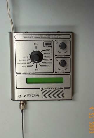
Click to zoom
Application Details
- Equipment Class
- CXX - Communications Rcvr for use w/ licensed Tx and CBs
- Date of Grant
- Jun 25, 2003
- Application Purpose
- Original Equipment
- Date of Application
- Apr 26, 2003
- Equipment Note
- FCC Part 15 receiver and unintentional radiator
- Frequency Range
- 928.00000000 - 932.00000000
- Country
- United States
Documents & Files
Document Text
Text extracted from the exhibit documents filed with the FCC. Open a document above to read the original.
Users Manual
WeatherTRAK Users Guide v1.33 Page 1 WeatherTRAK ® User Guide 1726 Corporate Circle Petaluma, California 94954 Fax (707) 769-9695 (707) 769-9696 (800) 362-8774 WeatherTRAK Users Guide v1.33 Page 2 ! !! ! TABLE OF CONTENTS Installation Guide................................................................ 3 Description of Front Panel............................................. 5 SETUP........................................................................................ 8 Test & Activate.................................................................... 10 PROGRAM............................................................................... 12 ADJUST..................................................................................... 14 REVIEW..................................................................................... 15 RAIN PAUSE............................................................................ 16 MANUAL.................................................................................. 16 RUN........................................................................................ 17 Troubleshooting.................................................................. 18 Frequently Asked Questions......................................... 20 FCC Information................................................................... 23 ©2003 by HydroPoint Data Systems, Inc. FIRST EDITION: Software Version 1.33 All rights reserved. No part of this Guide shall be reproduced, stored in a retrieval system, or transmitted by any means, electronic, mechanical, photocopying, recording, or otherwise, without written permission from HydroPoint Data Systems, Inc. Although every precaution has been taken in the preparation of this Guide, HydroPoint Data Systems, Inc. assumes no responsibility for errors or omissions. Neither is any liability assumed for damages resulting from the use of the information contained herein. The information in this manual is furnished for informational use only, is subject to change without notice, and should not be construed as a commitment by HydroPoint Data Systems, Inc. WeatherTRAK is a registered trademark of HydroPoint Data Systems, Inc. WeatherTRAK Users Guide v1.33 Page 3 ! !! ! Installation Guide Before You Start: Equipment and Power Requirements: INDOORS You need to have the WeatherTRAK controller and manual. There must be a power outlet within 6-8 feet of where the WeatherTRAK will be installed. If the valve wires are 16 gauge or heavier, you will need some 18-22 gauge solid valve extension wire (we recommend 20 gauge) and some wire nuts. OUTDOORS You need to have the WeatherTRAK controller, an outdoor box (from HydroPoint Data Systems, Inc.) and manual. There should be a junction box with 110VAC available near the proposed WeatherTRAK installation. You’ll need to bring power to the receptacle inside the outdoor box. Make sure you have some conduit and adapters available. You will need some 18-22 gauge solid valve extension wire (we recommend 20 gauge) and some wire nuts. Installation: Before you start, turn off the circuit breaker that powers the existing controller!!! Labeling: Make sure you know which station belongs to which wire before disconnecting the irrigation valve wires from the existing controller. Label or mark the wires accordingly. Also, make sure you identify the common wires and label them. Removing the Existing Controller: Unplug the power supply. If there is an internal transformer on the controller’s box, or the existing box is wired in, find the circuit breaker and turn it off. Then proceed to undo the existing wiring. Mounting the WeatherTRAK: INDOORS Make sure the new WeatherTRAK controller is at eye level for the expected operator and mount to the wall. If the valve wires do not reach, or the wires are 16 gauge or heavier, you may need to install a condolet box to bring WeatherTRAK Users Guide v1.33 Page 4 extension wires into the WeatherTRAK . Use 18 to 22 solid gauge valve wires so that they can fit inside the controller and connect the wires with wire nuts. Insert the previously labeled valve wires into the WeatherTRAK ’s connector strip securing each wire tip with a small straight blade screwdriver. There should be one or two common wires “C”; if a Rain Switch is being installed, wire in at “RS.” DO NOT REMOVE THE JUMPER AT THE "RS" POSITIONS UNLESS YOU INSTALL A RAIN SWITCH, OTHERWISE THE CONTROLLER WILL NOT IRRIGATE PROPERLY!!! (If your location uses a Master Valve or Pump, see the Master Valve section below.) When you replace the WeatherTRAK cover, be sure the COPY button moves freely and is not caught by the cover. Plug the transformer in the power outlet and plug into the WeatherTRAK . Turn the circuit breaker back on, verify all the valve wires are correctly installed, and then continue to SETUP . OUTDOORS Make sure the new outdoor box is at eye level for the expected operator and that there is clearance for the antenna sleeve. Mount the outdoor box to the wall using the appropriate anchors and screws. Use 18 to 22 solid gauge valve wires so that they can fit inside the controller, connect the wires with wire nuts, and conceal all connections behind the plate that holds the WeatherTRAK inside the outdoor box. Insert the previously labeled valve wires into the WeatherTRAK ’s connector strip securing each wire tip with a small straight blade screwdriver. There should be one or two common wires “C”; if a Rain Switch is being installed, wire in at “RS.” DO NOT REMOVE THE JUMPER AT THE "RS" POSITIONS UNLESS YOU INSTALL A RAIN SWITCH, OTHERWISE THE CONTROLLER WILL NOT IRRIGATE PROPERLY!!! (If your location uses a Master Valve or Pump, see the Master Valve section below.) When you replace the WeatherTRAK cover, be sure the COPY button moves freely and is not caught by the cover. The outdoor box requires direct connection to AC power. Make sure you connect the “ground” wire too. Use conventional conduit or flex conduit from the …
Text truncated - open the document above for the full version.
Block Diagram
GEL Report File HP01-2003Block DiagramFCC ID Q4LWT0003 GEL Report File HP01-2003April 26, 2003 Block Diagram
Cover Letter(s)
Glen Ellen Laboratories 1876 London Ranch Road Glen Ellen, CA 95442 ______________________________________________________________________________________________________________ (707) 996-8533 e-mail [email protected] (707) 996-2803 fax FCC OET re. Application for FCC ID Q4LWT0003 GEL Report File HP01-2003, dated April 26, 2003 for: WeatherTRAK irrigation controller made by HydroPoint Data Systems inc. 1726 Corporate Circle Petaluma, CA 94954 I confirm that the modification made to the WeatherTRAK irrigation controller, the addition of copper tape over the two metal shields on the input sections of the receiver, as described on the test report, will be implemented on all production units. Daniel C. Swann President, Glen Ellen Laboratories
External Photos
GEL Report File HP01-2003External PhotosFCC ID Q4LWT0003 Glen Ellen Laboratories1April 26, 2003 View of Front of EUT GEL Report File HP01-2003External PhotosFCC ID Q4LWT0003 Glen Ellen Laboratories2April 26, 2003 View of Back of EUT
ID Label/Location Info
GEL Report File HP01-2003ID Label/Location infoFCC ID Q4LWT0003 Glen Ellen LaboratoriesApril 26, 2003 PRODUCT LABELING FCC ID Label This is an exact facsimile of the label that will be used. Location of Label on EUT
Internal Photos
GEL Report File HP01-2003Internal PhotosFCC ID Q4LWT0003 Glen Ellen Laboratories1April 26, 2003 View of Front of PC Board GEL Report File HP01-2003Internal PhotosFCC ID Q4LWT0003 Glen Ellen Laboratories2April 26, 2003 View of Back of PC Board
Operational Description
GEL Report File HP01-2003Operational Description Rev. AFCC ID Q4LWT0003 Glen Ellen LaboratoriesApril 26, 2003 Operational Description WeatherTRAK Circuit Operation The WeatherTRAK Irrigation Controller consists of two basic subsystems: 1. A microController-based sprinkler timer of conventional design. 2. A radio receiver optimized to receive Paging signals in the 928-932MHz band. The basic operating frequency of the microController is 10.240 MHz; radiation of this signal and its harmonics are very low because all of the high frequency signals are on-chip with very short radiating conductors. The radio receiver is a conventional triple-conversion superheterodyne circuit. A quarter-wave monopole antenna is fed through a highly selective SAW filter to a preamplifier with a gain of about 15dB. The signal is then block downconverted to a 70MHz IF by a 1 GHz local oscillator and an active mixer (highside injection). The 1 GHz LO and the preamp/mixer chain is shielded by fully enclosing metal cans. The LO to RF leakage from the first mixer is suppressed by the input SAW filter. The 70 MHz signal is then bandpass filtered and further downconverted to 10.7MHz by a frequency agile local oscillator working between 78.7MHz and 82.6MHz, which performs the channel selection function. After filtering at 10.7MHz, the signal is downconverted again to a 455KHz IF by means of a 10.245MHz local oscillator and mixer. The 455 KHz is limited and processed through a data slicer and then digitally demodulated by a custom Motorola decoder chip. When an incoming message is detected, the microcontroller retrieves the message from the decoder chip and uses the data payload to influence the irrigation schedule in the sprinkler timer.
Test Report
TEST REPORT FOR FCC PART 15 COMPLIANCE FOR HydroPoint Data Systems inc. Prepared by Daniel C. Swann April 26, 2003 HydroPoint Data Systems WeatherTRAK Irrigation Controller FCC Part 15 receiver and unintentional radiator FCC ID Q4LWT0003 GEL Report File HP01-2003 GLEN ELLEN LABORATORIES 1876 London Ranch Road Glen Ellen, CA 95442 GEL Report File HP01-2003FCC ID Q4LWT0003 Glen Ellen Laboratories2April 26, 2003 MEASUREMENT/TECHNICAL REPORT HydroPoint Data Systems inc. FCC ID Q4LWT0003 This report concerns:An Original Grant Equipment type:FCC Part 15 receiver and unintentional radiator Deferred grant requested:no Transition rules per 15.37:no Report prepared by:Daniel C. Swann Glen Ellen Laboratories 1876 London Ranch Road Glen Ellen, CA 95442 (707) 996-8533 (707) 996-2803 fax [email protected] Measurements Certified by:Daniel C. Swann Date 04/26/03 GEL Report File: HP01-2003 GEL Report File HP01-2003FCC ID Q4LWT0003 Glen Ellen Laboratories3April 26, 2003 TABLE OF CONTENTS 1GENERAL INFORMATION 1.1Product Description 1.2Related Submittal and Grant 1.3Tested System Details 1.4Test Methodology 1.5Test Facility 2FCC STATEMENT IN USER MANUAL 3SYSTEM TEST CONFIGURATION 3.1Justification 3.2EUT Exercise Software 3.3Special Accessories 3.4Equipment Modifications 3.5Configuration of Tested System Figure 3.1Configuration of Tested System 4CONDUCTED EMISSIONS DATA 5RADIATED EMISSIONS DATA 5.1Data 5.2Field Strength Calculations ATTACHMENTS ID Label/Location Info External Photographs Block Diagrams Schematics Test Setup Photographs Users Manual Internal Photographs3 Operational Descriptions Transmitter Schematics Photographs Of Tested EUT This report contains 13 pages, and may be reproduced in full only. Partial reproduction may only be done with the written consent of Glen Ellen Laboratories. GEL Report File HP01-2003FCC ID Q4LWT0003 Glen Ellen Laboratories4April 26, 2003 1GENERAL INFORMATION 1.1Product Description The HydroPoint Data Systems WeatherTRAK irrigation controller is receiver/controller to receive weather information from a pager signal and control irrigation solenoid valves. The unit receives pager signals between 928 and 932 MHz through a direct mount 1/4 wave antenna utilizing a TNC connector. The connection to the irrigation solenoid valves is made with copper wires connected to a terminal strip on the PC board. The product is shipped with either 8, or 12, control circuits loaded on the PC board. See the User Manual attachment for a description of the available controls on the EUT. The product is powered by a HydroPoint wall mount 120 VAC to 24 VDC at 600 mA, and 8 VDC at 300 mA transformer, with a shielded cable 94 inches long, Model MA48P1S2168. The internal construction is single two layer PC board and a piggyback LCD display board. Portions of the receiver circuit are covered by two metal shields. The housing for the product is aluminum, in two pieces. GEL Report File HP01-2003FCC ID Q4LWT0003 Glen Ellen Laboratories5April 26, 2003 1.2Related Submittal or Grant There are no related submittals or grants. 1.3Tested System Details EUT HydroPoint Data Systems WeatherTRAK irrigation controller , Serial Number 003192. Made by: HydroPoint Data Systems inc. 1726 Corporate Circle Petaluma, CA 94954 The circuit uses two clock frequencies of 10.240 MHz and 14.400 MHz. See the Block Diagram for more information. GEL Report File HP01-2003FCC ID Q4LWT0003 Glen Ellen Laboratories6April 26, 2003 1.4Test Methodology The radiated tests were performed in accordance with the ANSI C63.4-1992 standard. See Figure 3.1 and the photographs for details of the test setup. Radiated testing was performed at an antenna to EUT distance of 3 meters. For conducted measurements, the LISN's (50 uH Artificial Mains Networks) were placed on, and grounded to, the turntable surface. 1.5Test Facility The Glen Ellen Laboratories open field test site complies with the requirements specified by VDE 0876/9.78, VDE 0877 Part 1/11.81, VDE 0877 Part 2/2.85, CISPR 16, CISPR 22, and ANSI C63.4-1992. The test site closely follows the theoretical normalized site attenuation specifications for both horizontal and vertical polarizations. The site has been fully described in a report dated November 3, 2002, submitted to the FCC, and accepted in a letter dated November 8, 2002 (Registration Number 90613.) Test equipment used included: 1.Hewlett Packard 8591EM spectrum analyzer, cal due 06-20-03. 2.Sonoma Instruments 317 preamplifier, 10 kHz to 2.5 GHz, cal due 03-25-04. 3.GEL BIC9414 biconical antenna, 30 MHz to 300 MHz, cal due 06-24-03. 4.GEL LPA-3 log periodic antenna, 275 MHz to 2 GHz, cal due 06-24-03. 5.Hewlett Packard 8566B opt L24 spectrum analyzer, cal due 06-20-03. 6.ETS Horn Antenna, 1 GHz to 18 GHz, cal due 07-29-03. 7.GEL AP2-10 preamplifier, 2 GHz to 10 GHz, cal due 9-08-03. 8.EMCO LISN, model number 3825/2, cal due 06-01-03. GEL Report File HP01-2003FCC ID Q4LWT0003 Glen Ellen Laboratories7April 26, 2003 2FCC Statement in User Manual The following statement appears in a prominent location in the text of the user manual: Note: This equipment has been tested and found to comply with the limits for a Class B digital device, pursuant to part 15 of the FCC Rules. These limits are designed to provide reasonable protection against harmful interference in a residential installation. This equipment generates, uses and can radiate radio frequency energy and, if not installed and used in accordance with the instructions, may cause harmful interference to radio communications. However, there is no guarantee that interference will not occur in a particular installation. If this equipment does cause harmful interference to radio or television reception, which can be determined by turning the equipment off and on, the user is encouraged to try to correct the interference by one or more of the following measures: --Reorient or relocate the receiving antenna. --Increase the separation between the equipment and receiver. --Connect the e…
Text truncated - open the document above for the full version.
Test Setup Photos
GEL Report File HP01-2003Test Setup PhotographsFCC ID Q4LWT0003 Glen Ellen Laboratories1April 26, 2003 Test Setup Photographs Front View of EUT for Conducted Test GEL Report File HP01-2003Test Setup PhotographsFCC ID Q4LWT0003 Glen Ellen Laboratories2April 26, 2003 Test Setup Photographs Rear View of EUT for Conducted Test GEL Report File HP01-2003Test Setup PhotographsFCC ID Q4LWT0003 Glen Ellen Laboratories3April 26, 2003 Test Setup Photographs Front View of EUT for Radiated Test GEL Report File HP01-2003Test Setup PhotographsFCC ID Q4LWT0003 Glen Ellen Laboratories4April 26, 2003 Test Setup Photographs Rear View of EUT for Radiated Test
Contact Information
Applicant
Mike Marian(CTO)
Test Firm
Glen Ellen LaboratoriesDaniel Swann
Technical Specifications
| # | Rule Parts | Frequency Range | Power Output |
|---|---|---|---|
| 1 | 15B | 928 MHz - 932 MHz | - |
Other Applications from HydroPoint data systems, inc.
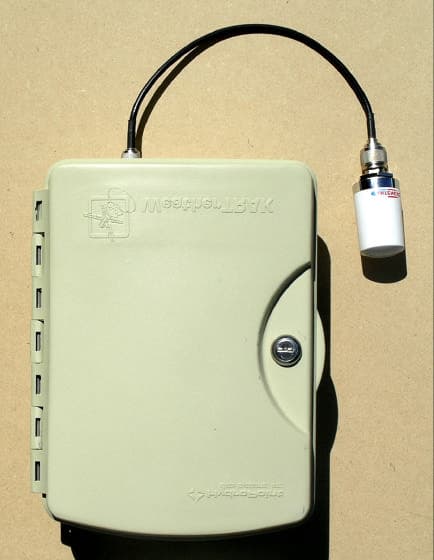
Q4LWT008
Aug 23, 2004Pager Receiver for Irrigation Control
Equipment Class
CYY - Communications Receiver used w/Pt 15 Transmitter