Q4LWT008Pager Receiver for Irrigation Control
HydroPoint data systems, inc.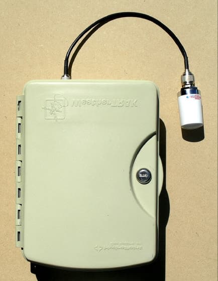
Click to zoom
Application Details
- Equipment Class
- CYY - Communications Receiver used w/Pt 15 Transmitter
- Date of Grant
- Aug 23, 2004
- Application Purpose
- Original Equipment
- Date of Application
- Jul 06, 2004
- Equipment Note
- Pager Receiver for Irrigation Control
- Frequency Range
- 902.00000000 - 928.00000000
- Country
- United States
Documents & Files
Document Text
Text extracted from the exhibit documents filed with the FCC. Open a document above to read the original.
Users Manual
Table of Contents Table of Contents I Introduction ..................................................................1Welcome to the World of WeatherTRAK ® ! ..................................1 Chapter 1: Getting to Know Your WeatherTRAK ET Plus ................................................5 Overview of the Controller ............................................................6Selecting and Adjusting the Settings ............................................9Chapter 2: Setting Up Your WeatherTRAK ET Plus ..............................................13 Setting the Irrigation Start Time ..................................................14Setting the Water Window............................................................14Setting the High ET Start ..............................................................15Setting the Clock ............................................................................16Setting the Time Zone ..................................................................16Setting Auto Daylight Savings ....................................................17Setting the Maximum Active Stations ........................................17Viewing the Serial Number ..........................................................18Viewing the Phase Integrity ........................................................18Setting the Lock Phase ..................................................................18Displaying the Microzone ............................................................19Displaying the WT Version ..........................................................20Setting the Water District Number..............................................21Setting the Radio Antenna............................................................22Chapter 3: Programming Your WeatherTRAK ET Plus ..............................................25 Setting Schedules ........................................................................26Introduction to Programming ....................................................30Programming Fully Automated ................................................31User Program With ET ................................................................42User Program No ET ....................................................................49Copying ..........................................................................................49Reviewing ......................................................................................55Adjusting ........................................................................................57 Table of Contents III Chapter 4: Using Special Features ..........................63Running ..........................................................................................64Using Rain Pause ..........................................................................65Operating Manually ......................................................................67Understanding Alerts ....................................................................71Using ET ..........................................................................................73Using Display Adjust ....................................................................74Using Help ......................................................................................75Setting to Off ..................................................................................77Activating the Rain Service ..........................................................78Setting the Zip Code......................................................................78Setting the ET Zone ......................................................................79Displaying the Group Number....................................................79Setting the Maximum Backup ET ..............................................80Appendix A: Quick Reference Guide ....................83Getting Started ..............................................................................83Schedules ........................................................................................83Programs ........................................................................................84Copy ................................................................................................85Review ............................................................................................85Adjust (Auto Mode Only) ............................................................86Manual ............................................................................................86Rain Pause ......................................................................................87Appendix B: Troubleshooting Guide ....................89Alert Troubleshooting ..................................................................89The Controller Programs Correctly But There is No Station Output From the Controller ..........................................90My Landscape is Too Wet ............................................................90My Landscape is Too Dry ............................................................90Adjust is Not Working ..................................................................90Controller Just Installed, Activated and Still Beeping ............91What Do the Beeps Mean ............................................................91The Display is Blank......................................................................91The Display is Frozen....................................................................92ET Display Has a “P” After It ......................................................92Week 1 in the Review Screen is Much Different Than Weeks 2 Through 8 ........................................................................92The Display in REVIEW Shows “99+” Minutes of Runtime ..........................................................................................93 Table of Contents II Appendix …
Text truncated - open the document above for the full version.
Block Diagram
Report File HydroPoint 01-2004 Block Diagram FCC ID Q4LWT008 Glen Ellen Laboratories June 17, 2004 Block Diagram d o w n c o n v e r t e r R e n e s a s H 8 S 2 2 3 8 m i c r o c o n t r o l l e r i n t e r c o n n e c t b o a r d F M d e m o d D i s p l a y O u t p u t s o l e n o i d s D a t a d e c o d e r K n o b s 9 . 8 3 0 4 M H z O s c 3 0 7 k H z I F ~ 9 3 0 M H z L O 1 6 . 0 0 M H z O s c e x t e r n a l a n t e n n a i n p u t i n t e r n a l a n t e n n a i n p u t
Cover Letter(s)
Glen Ellen Laboratories 1876 London Ranch Road Glen Ellen, CA 95442 _______________________________________________________________________________________________________ (707) 996-8533 e-mail [email protected] (707) 996-2803 fax Linda Elliott FCC OET Correspondence Reference Number: 27267 731 Confirmation Number: EA543612 re. Application for FCC ID Q4LWT008 GEL Report File HydroPoint 01-2004, dated June 17, 2004 for: WeatherTRAK ET plus irrigation controller, made by HydroPoint Data Systems inc. 1726 Corporate Circle Petaluma, CA 94954 The FCC ID label attachment has been changed to show the correct FCC ID number, Q4LWT008. The test report has been corrected to say that wires were connected to all 12 valve positions, the master valve control circuit, and the sensor input connection. Both of these Adobe Acrobat files have ‘corrected’ in the file name. Best regards, Daniel C. Swann President, Glen Ellen Laboratories
External Photos
Report File HydroPoint 01-2004 External Photographs FCC ID Q4LWT008 Glen Ellen Laboratories 1 June 17, 2004 External Photographs of EUT Front View of EUT with cover closed, showing external antenna. Report File HydroPoint 01-2004 External Photographs FCC ID Q4LWT008 Glen Ellen Laboratories 2 June 17, 2004 External Photographs of EUT Rear View of EUT, showing external antenna and power cable.
ID Label/Location Info
Report File HydroPoint 01-2004 ID Label/Location Info FCC ID Q4LWT008 Glen Ellen Laboratories June 17, 2004 ID Label WeatherTRAKETplus IrrigationController HydroPointDataSystems,Inc. FCCID:Q4LWT004 Thisdevicecomplieswithpart15oftheFCCRules. Operationissubjecttothefollowingtwoconditions: (1)Thisdevicemaynotcauseharmfulinterference,and (2)thisdevicemustacceptanyinterferencereceived, includinginterferencethatmaycauseundesiredoperation. Report File HydroPoint 01-2004 ID Label/Location Info FCC ID Q4LWT008 Glen Ellen Laboratories 2 April 26, 2003 Label Location
ID Label/Location Info
Report File HydroPoint 01-2004 ID Label/Location Info FCC ID Q4LWT008 Glen Ellen Laboratories June 17, 2004 ID Label WeatherTRAKETplus IrrigationController HydroPointDataSystems,Inc. FCCID:Q4LWT008 Thisdevicecomplieswithpart15oftheFCCRules. Operationissubjecttothefollowingtwoconditions: (1)Thisdevicemaynotcauseharmfulinterference,and (2)thisdevicemustacceptanyinterferencereceived, includinginterferencethatmaycauseundesiredoperation. Report File HydroPoint 01-2004 ID Label/Location Info FCC ID Q4LWT008 Glen Ellen Laboratories 2 April 26, 2003 Label Location
Internal Photos
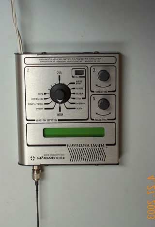
Report File HydroPoint 01-2004 Internal Photographs FCC ID Q4LWT008 Glen Ellen Laboratories 1 June 17, 2004 Photographs of EUT Front View of EUT with cover open, showing user controls. Report File HydroPoint 01-2004 Internal Photographs FCC ID Q4LWT008 Glen Ellen Laboratories 2 June 17, 2004 Photographs of EUT View of EUT showing front cover open, and controller PC board mount rotated out to access interconnect board. Report File HydroPoint 01-2004 Internal Photographs FCC ID Q4LWT008 Glen Ellen Laboratories 3 June 17, 2004 Photographs of EUT View of cover over controller PC board, external antenna connection, and interconnect board. Report File HydroPoint 01-2004 Internal Photographs FCC ID Q4LWT008 Glen Ellen Laboratories 4 June 17, 2004 Photographs of EUT Front View of EUT controller board. Report File HydroPoint 01-2004 Internal Photographs FCC ID Q4LWT008 Glen Ellen Laboratories 5 June 17, 2004 Photographs of EUT Rear View of EUT controller board showing antenna connection for external antenna. Report File HydroPoint 01-2004 Internal Photographs FCC ID Q4LWT008 Glen Ellen Laboratories 6 June 17, 2004 Photographs of EUT Front view of of interconnect board. Report File HydroPoint 01-2004 Internal Photographs FCC ID Q4LWT008 Glen Ellen Laboratories 7 June 17, 2004 Photographs of EUT Rear view of interconnect board.
Operational Description
Report File HydroPoint 01-2004 Operational Description FCC ID Q4LWT008 Glen Ellen Laboratories June 17, 2004 Operational Description WeatherTRAK Circuit Operation The WeatherTRAK Irrigation Controller consists of two basic subsystems: 1. A microController-based sprinkler timer of conventional design. 2. A radio receiver optimized to receive Paging signals in the 928-932MHz band. The basic operating frequency of the microController is 16.000 MHz; radiation of this signal and its harmonics are very low because all of the high frequency signals are on-chip with very short radiating conductors. The radio receiver is a direct conversion superheterodyne circuit. A ceramic chip antenna, or an Antenex TRA8903P 890-960MHz Helical antenna, is fed to a preamplifier with a gain of about 15dB. The signal is then down-converted to a 307 kHz IF by a local oscillator. The 307 kHz signal is then digitally filtered and demodulated and decoded. When an incoming message is detected, the microcontroller retrieves the message from the decoder chip and uses the data payload to influence the irrigation schedule in the sprinkler timer.
Test Report
TEST REPORT FOR FCC PART 15 COMPLIANCE For HydroPoint Data Systems inc. Prepared by Daniel C. Swann June 17, 2004 HydroPoint Data Systems WeatherTRAK ET plus Irrigation Controller FCC Part 15 Receiver FCC ID Q4LWT008 GEL Report File HydroPoint 01-2004 GLEN ELLEN LABORATORIES 1876 London Ranch Road Glen Ellen, CA 95442 GEL Report File HydroPoint 01-2004 FCC ID Q4LWT008 Glen Ellen Laboratories 2 June 17, 2004 MEASUREMENT/TECHNICAL REPORT HydroPoint Data Systems inc. FCC ID Q4LWT008 This report concerns: An Original Grant Equipment type: FCC Part 15 receiver Deferred grant requested: no Transition rules per 15.37: no Report prepared by: Daniel C. Swann Glen Ellen Laboratories 1876 London Ranch Road Glen Ellen, CA 95442 (707) 996-8533 (707) 996-2803 fax [email protected] Measurements Certified by: Daniel C. Swann Date 06/17/04 GEL Report File: HydroPoint 01-2004 GEL Report File HydroPoint 01-2004 FCC ID Q4LWT008 Glen Ellen Laboratories 3 June 17, 2004 TABLE OF CONTENTS 1 GENERAL INFORMATION 1.1 Product Description 1.2 Related Submittal and Grant 1.3 Tested System Details 1.4 Test Methodology 1.5 Test Facility 2 FCC STATEMENT IN USER MANUAL 3 SYSTEM TEST CONFIGURATION 3.1 Justification 3.2 EUT Exercise Software 3.3 Special Accessories 3.4 Equipment Modifications 3.5 Configuration of Tested System Figure 3.1 Configuration of Tested System 4 CONDUCTED EMISSIONS DATA 5 RADIATED EMISSIONS DATA 5.1 Data 5.2 Field Strength Calculations ATTACHMENTS ID Label/Location Info External Photographs Block Diagram Test Setup Photographs Users Manual Internal Photographs Operational Description This report contains 14 pages, and may be reproduced in full only. GEL Report File HydroPoint 01-2004 FCC ID Q4LWT008 Glen Ellen Laboratories 4 June 17, 2004 1 GENERAL INFORMATION 1.1 Product Description The HydroPoint Data Systems WeatherTRAK ET plus irrigation controller is receiver/controller to receive weather information from a pager signal and control irrigation solenoid valves. The unit receives pager signals between 928 and 932 MHz through either an internal antenna on the PC board, or an external antenna, Antenex TRA8903P 890-960MHz Helical with a 12 inch coax cable, utilizing a TNC connector on the bottom of the case. The antenna choice is made with the front panel controls. The product has connections for 12 control circuits, a master valve control circuit, and a sensor input connection. See the User Manual attachment for a description of the available controls on the EUT. The product is powered by a 120 VAC, with an 8 foot unshielded power cord. The internal construction is one 4 layer receiver-decoder-control PC board, and one passive 2 layer wire connection board with lightening protection devices and terminal strip connection blocks for the external connection wires. The housing parts consist of a external case, with a front door, an additional hinged cover with the receiver-decoder-control PC board mounted on it, and a cover over the back of the receiver-decoder- control PC board. All of these housing parts for the product are nonconductive plastic. GEL Report File HydroPoint 01-2004 FCC ID Q4LWT008 Glen Ellen Laboratories 5 June 17, 2004 1.2 Related Submittal or Grant There are no related submittals or grants. 1.3 Tested System Details EUT HydroPoint Data Systems WeatherTRAK ET plus irrigation controller , Serial Number 007158. Made by: HydroPoint Data Systems inc. 1726 Corporate Circle Petaluma, CA 94954 The circuit uses two clock frequencies of 9.8304 and 16.000 MHz. See the Block Diagram for more information. GEL Report File HydroPoint 01-2004 FCC ID Q4LWT008 Glen Ellen Laboratories 6 June 17, 2004 1.4 Test Methodology The radiated tests were performed in accordance with the ANSI C63.4-1992 standard. See Figure 3.1 and the photographs for details of the test setup. Radiated testing was performed at an antenna to EUT distance of 3 meters. Radiated measurements were made from 30 MHz to 5 GHz, as specified in Part 15.33. For conducted measurements, the LISN's (50 uH Artificial Mains Networks) were placed on, and grounded to, the turntable surface. 1.5 Test Facility The Glen Ellen Laboratories open field test site complies with the requirements specified by VDE 0876/9.78, VDE 0877 Part 1/11.81, VDE 0877 Part 2/2.85, CISPR 16, CISPR 22, and ANSI C63.4-1992. The test site closely follows the theoretical normalized site attenuation specifications for both horizontal and vertical polarizations. The site has been fully described in a report dated November 3, 2002, submitted to the FCC, and accepted in a letter dated November 8, 2002 (Registration Number 90613.) Test equipment used included: 1. Hewlett Packard 8591EM spectrum analyzer, cal due 04-10-05. 2. Sonoma Instruments 317 preamplifier, 10 kHz to 2.5 GHz, cal due 04-14-05. 3. GEL BIC9414 biconical antenna, 30 MHz to 300 MHz, cal due 05-24-05. 4. GEL LPA-3 log periodic antenna, 275 MHz to 2 GHz, cal due 05-24-05. 5. Hewlett Packard 8566B opt L24 spectrum analyzer, cal due 04-15-05. 6. ETS Horn Antenna, 1 GHz to 18 GHz, cal due 09-24-04. 7. GEL AP2-10 preamplifier, 1 GHz to 10 GHz, cal due 09-20-04. 8. EMCO LISN, model number 3825/2, cal due 05-23-05. GEL Report File HydroPoint 01-2004 FCC ID Q4LWT008 Glen Ellen Laboratories 7 June 17, 2004 2 FCC Statement in User Manual The following statement appears in a prominent location in the text of the user manual: Note: This equipment has been tested and found to comply with the limits for a Class B digital device, pursuant to part 15 of the FCC Rules. These limits are designed to provide reasonable protection against harmful interference in a residential installation. This equipment generates, uses and can radiate radio frequency energy and, if not installed and used in accordance with the instructions, may cause harmful interference to radio communications. However, there is no guarantee that interference will not occur in a particular installation. If this equipment does cause harmful interference to radi…
Text truncated - open the document above for the full version.
Test Report
TEST REPORT FOR FCC PART 15 COMPLIANCE For HydroPoint Data Systems inc. Prepared by Daniel C. Swann June 17, 2004 HydroPoint Data Systems WeatherTRAK ET plus Irrigation Controller FCC Part 15 Receiver FCC ID Q4LWT008 GEL Report File HydroPoint 01-2004 GLEN ELLEN LABORATORIES 1876 London Ranch Road Glen Ellen, CA 95442 GEL Report File HydroPoint 01-2004 FCC ID Q4LWT008 Glen Ellen Laboratories 2 June 17, 2004 MEASUREMENT/TECHNICAL REPORT HydroPoint Data Systems inc. FCC ID Q4LWT008 This report concerns: An Original Grant Equipment type: FCC Part 15 receiver Deferred grant requested: no Transition rules per 15.37: no Report prepared by: Daniel C. Swann Glen Ellen Laboratories 1876 London Ranch Road Glen Ellen, CA 95442 (707) 996-8533 (707) 996-2803 fax [email protected] Measurements Certified by: Daniel C. Swann Date 06/17/04 GEL Report File: HydroPoint 01-2004 GEL Report File HydroPoint 01-2004 FCC ID Q4LWT008 Glen Ellen Laboratories 3 June 17, 2004 TABLE OF CONTENTS 1 GENERAL INFORMATION 1.1 Product Description 1.2 Related Submittal and Grant 1.3 Tested System Details 1.4 Test Methodology 1.5 Test Facility 2 FCC STATEMENT IN USER MANUAL 3 SYSTEM TEST CONFIGURATION 3.1 Justification 3.2 EUT Exercise Software 3.3 Special Accessories 3.4 Equipment Modifications 3.5 Configuration of Tested System Figure 3.1 Configuration of Tested System 4 CONDUCTED EMISSIONS DATA 5 RADIATED EMISSIONS DATA 5.1 Data 5.2 Field Strength Calculations ATTACHMENTS ID Label/Location Info External Photographs Block Diagram Test Setup Photographs Users Manual Internal Photographs Operational Description This report contains 14 pages, and may be reproduced in full only. GEL Report File HydroPoint 01-2004 FCC ID Q4LWT008 Glen Ellen Laboratories 4 June 17, 2004 1 GENERAL INFORMATION 1.1 Product Description The HydroPoint Data Systems WeatherTRAK ET plus irrigation controller is receiver/controller to receive weather information from a pager signal and control irrigation solenoid valves. The unit receives pager signals between 928 and 932 MHz through either an internal antenna on the PC board, or an external antenna, Antenex TRA8903P 890-960MHz Helical with a 12 inch coax cable, utilizing a TNC connector on the bottom of the case. The antenna choice is made with the front panel controls. The product has connections for 12 control circuits, a master valve control circuit, and a sensor input connection. See the User Manual attachment for a description of the available controls on the EUT. The product is powered by a 120 VAC, with an 8 foot unshielded power cord. The internal construction is one 4 layer receiver-decoder-control PC board, and one passive 2 layer wire connection board with lightening protection devices and terminal strip connection blocks for the external connection wires. The housing parts consist of a external case, with a front door, an additional hinged cover with the receiver-decoder-control PC board mounted on it, and a cover over the back of the receiver-decoder- control PC board. All of these housing parts for the product are nonconductive plastic. GEL Report File HydroPoint 01-2004 FCC ID Q4LWT008 Glen Ellen Laboratories 5 June 17, 2004 1.2 Related Submittal or Grant There are no related submittals or grants. 1.3 Tested System Details EUT HydroPoint Data Systems WeatherTRAK ET plus irrigation controller , Serial Number 007158. Made by: HydroPoint Data Systems inc. 1726 Corporate Circle Petaluma, CA 94954 The circuit uses two clock frequencies of 9.8304 and 16.000 MHz. See the Block Diagram for more information. GEL Report File HydroPoint 01-2004 FCC ID Q4LWT008 Glen Ellen Laboratories 6 June 17, 2004 1.4 Test Methodology The radiated tests were performed in accordance with the ANSI C63.4-1992 standard. See Figure 3.1 and the photographs for details of the test setup. Radiated testing was performed at an antenna to EUT distance of 3 meters. Radiated measurements were made from 30 MHz to 5 GHz, as specified in Part 15.33. For conducted measurements, the LISN's (50 uH Artificial Mains Networks) were placed on, and grounded to, the turntable surface. 1.5 Test Facility The Glen Ellen Laboratories open field test site complies with the requirements specified by VDE 0876/9.78, VDE 0877 Part 1/11.81, VDE 0877 Part 2/2.85, CISPR 16, CISPR 22, and ANSI C63.4-1992. The test site closely follows the theoretical normalized site attenuation specifications for both horizontal and vertical polarizations. The site has been fully described in a report dated November 3, 2002, submitted to the FCC, and accepted in a letter dated November 8, 2002 (Registration Number 90613.) Test equipment used included: 1. Hewlett Packard 8591EM spectrum analyzer, cal due 04-10-05. 2. Sonoma Instruments 317 preamplifier, 10 kHz to 2.5 GHz, cal due 04-14-05. 3. GEL BIC9414 biconical antenna, 30 MHz to 300 MHz, cal due 05-24-05. 4. GEL LPA-3 log periodic antenna, 275 MHz to 2 GHz, cal due 05-24-05. 5. Hewlett Packard 8566B opt L24 spectrum analyzer, cal due 04-15-05. 6. ETS Horn Antenna, 1 GHz to 18 GHz, cal due 09-24-04. 7. GEL AP2-10 preamplifier, 1 GHz to 10 GHz, cal due 09-20-04. 8. EMCO LISN, model number 3825/2, cal due 05-23-05. GEL Report File HydroPoint 01-2004 FCC ID Q4LWT008 Glen Ellen Laboratories 7 June 17, 2004 2 FCC Statement in User Manual The following statement appears in a prominent location in the text of the user manual: Note: This equipment has been tested and found to comply with the limits for a Class B digital device, pursuant to part 15 of the FCC Rules. These limits are designed to provide reasonable protection against harmful interference in a residential installation. This equipment generates, uses and can radiate radio frequency energy and, if not installed and used in accordance with the instructions, may cause harmful interference to radio communications. However, there is no guarantee that interference will not occur in a particular installation. If this equipment does cause harmful interference to radi…
Text truncated - open the document above for the full version.
Test Setup Photos
Report File HydroPoint 01-2004 Test Setup Photographs FCC ID Q4LWT008 Glen Ellen Laboratories 1 June 17, 2004 Test Setup Photographs Front View of EUT for Conducted Test (Non conductive spacers and black duct tape were used to hold the EUT in the upright position on the tabletop.) Report File HydroPoint 01-2004 Test Setup Photographs FCC ID Q4LWT008 Glen Ellen Laboratories 2 June 17, 2004 Test Setup Photographs Rear View of EUT for Conducted Test Report File HydroPoint 01-2004 Test Setup Photographs FCC ID Q4LWT008 Glen Ellen Laboratories 3 June 17, 2004 Test Setup Photographs Front View of EUT for Radiated Test, Internal Antenna Report File HydroPoint 01-2004 Test Setup Photographs FCC ID Q4LWT008 Glen Ellen Laboratories 4 June 17, 2004 Test Setup Photographs Rear View of EUT for Radiated Test, Internal Antenna Report File HydroPoint 01-2004 Test Setup Photographs FCC ID Q4LWT008 Glen Ellen Laboratories 5 June 17, 2004 Test Setup Photographs Front View of EUT for Radiated Test, External Antenna (External antenna is taped to table to the left of the EUT, in this view.) Report File HydroPoint 01-2004 Test Setup Photographs FCC ID Q4LWT008 Glen Ellen Laboratories 6 June 17, 2004 Test Setup Photographs Rear View of EUT for Radiated Test, External Antenna (External antenna is taped to table to the right of the EUT, in this view.)
Contact Information
Applicant
Mike Marian(CTO)
Technical Contact
HydroPoint data systems, incMike Marian
[email protected]707 769 9696
1726 Corporate Circle · Petaluma, California · United States
Non-Technical Contact
HydroPoint data systems, incMike Marian
[email protected]707 769 9696
Test Firm
Glen Ellen LaboratoriesDaniel Swann
Technical Specifications
| # | Rule Parts | Frequency Range | Power Output |
|---|---|---|---|
| 1 | 15B | 902 MHz - 928 MHz | - |
Other Applications from HydroPoint data systems, inc.
Q4LWT0003
Jun 25, 2003FCC Part 15 receiver and unintentional radiator
Equipment Class
CXX - Communications Rcvr for use w/ licensed Tx and CBs