Q4N1500Wideband 2.4GHz Audio/ Video Transmitter
DataWave Technologies LLC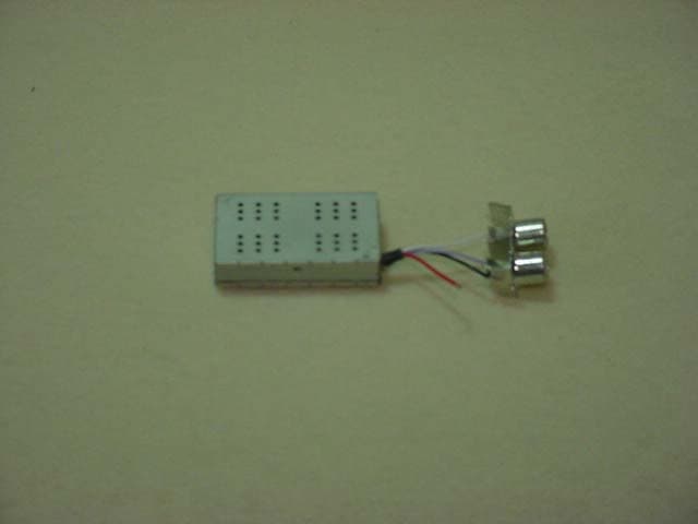
Click to zoom
Application Details
- Equipment Class
- TNB - Licensed Non-Broadcast Station Transmitter
- Date of Grant
- Jun 16, 2003
- Application Purpose
- Original Equipment
- Date of Application
- Jun 16, 2003
- Equipment Note
- Wideband 2.4GHz Audio/ Video Transmitter
- Frequency Range
- 2458.00000000 - 2474.00000000
- Company
- DataWave Technologies LLC
- Country
- United States
Documents & Files
Document Text
Text extracted from the exhibit documents filed with the FCC. Open a document above to read the original.
Users Manual
2.4GHz 300mW Part 90 Wideband FM Audio/Video Transmit Module PN 1500-2467-33 User’s Manual FCC Issue Version 1.02 DataWave Technologies, LLC • 190 Stanley Court • Lawrenceville, GA 30045 Voice: 678-442-1234 • FAX 678-442-1295 • www.datawavetechnologies.com 2 Copyright Information All information within this manual are copyrighted and all rights are reserved by DataWave Technologies, LLC. Copying, duplicating, selling, or otherwise distributing any part of this product without the prior consent of an authorized representative of DataWave Technologies, LLC is prohibited. Revision Listing Revision Number Description 1.00 Initial Release Agency Approval Agency Identification US- FCC Q4N1500 FCC Notice FCC Label Warning: This device complies with Part 15 of the FCC Rules. Operation is subject to the following two conditions: (1) The device may not cause harmful interference and (2) This device must accept any interference received, including interference that may cause undesired operation. DataWave Technologies, LLC • 190 Stanley Court • Lawrenceville, GA 30045 Voice: 678-442-1234 • FAX 678-442-1295 • www.datawavetechnologies.com 3 Information to the User Any changes or modifications not expressly approved by DataWave Technologies, LLC could void the user’s authority to operate the equipment. It is recommended that the user contact DataWave for installation and integration guidelines for their product. This equipment has been tested and found to comply with the limits for a Class B digital device, pursuant to Part 15 of the FCC Rules. These limits are designed to provide reasonable protection against harmful interference in a residential installation. This equipment generates, uses, and can radiate radio frequency energy, and if not installed and used in accordance with the instructions, may cause harmful interference to radio communications. However, there is no guarantee that interference will not occur in a particular installation. If this equipment does cause harmful interference to radio or television reception, which can be determined by turning the equipment off and on, the user is encouraged to try to correct the interference by one or more of the following measures: • Reorient or relocate the receiving antenna. • Increase the separation between the equipment and receiver. • Connect the equipment into an outlet on a circuit different from that to which the receiver is connected. • Consult the dealer or an experienced radio/TV technician for help. FCC Labeling RF Exposure Warning: All original equipment manufacturers (OEM) integrating this device within their products must maintain a minimum distance of 20cm between the installed antenna and the user or general population. For applications requiring handheld or body worn operations OEMS must submit their product to the FCC for Specific Absorption Rate (SAR) testing. Warning: All original equipment manufacturers (OEM) integrating this device within their products must comply with FCC labeling requirements. A clearly visible label must be displayed on the outside of the OEM enclosure specifying that the device contains the FCC identifier listed on the FCC label shown below. DataWave Technologies, LLC • 190 Stanley Court • Lawrenceville, GA 30045 Voice: 678-442-1234 • FAX 678-442-1295 • www.datawavetechnologies.com 4 Overview This manual contains information regarding the hardware and operational aspects of the DataWave 1500 series transmit modules. This information includes theory of operation and integration guidelines to aid the OEM during installation. The 1500-2467-33 is designed to operate in the 2450MHz- 2483.5MHz license free ISM frequency band. The module can be ordered in a 2 channel configuration and when used with the 1701-2450- 33 can cover short to intermediate ranges of up to 1000ft L.O.S. The 1500-2467-33 is ideal for short range communication links requiring full resolution video and single channel audio capabilities. Specifications Table 1 Product Specifications MinTypMax Operating Voltage4.8555.15 Volts Regulated Max RF Output Power285300315 mW Carrier Pow er RF Bandwidth7.7588.25 MHz First Harmonic Rej.-57-60-65 dBc Ref erence to Carrier Pow er Frequency Range24502483 MHz Channel 12458 MHz Channel 22474 MHz RF Power Output1300 mW Operating Temp.-4085 ºC Modulation Type Dimensions Antenna Interface We ig h t VSWR Antenna Port Curent Consumption Specification ParameterUnit 485510535 mA Pout=300mW 2:1 @ 50Ω 3 oz Condition Frequency Modulation MMCX **see approved antenna listing DataWave Technologies, LLC • 190 Stanley Court • Lawrenceville, GA 30045 Voice: 678-442-1234 • FAX 678-442-1295 • www.datawavetechnologies.com 5 Video Signal Conditioning Audio inter- carrier modulator Modulator 5.5MHz (120 kHz BW) PA Video in Audio in Antenna Composite Baseband Information CCIR-405 Pre-emphasized Level Adjusted video FM inter-carrier @ 5.5MHz 75usec audio pre-emphasis AC baseband summing RF Signal Adjustable Power Output Theory of Operation This module transmits NTSC/PAL video and 1Vp-p audio signals using a standard wideband frequency modulation method. The module consists of 4 blocks for the transmission of audio/video at 2.4GHz: Figure 1 Transmitter Block Diagram Block Diagram Description The Video Signal Conditioning portion of the transmitter is used to add video pre-emphasis and divide down the incoming video level to provide an adjustable deviation constant for a desired bandwidth. The Audio Inter-Carrier Modulator block takes a 1Vp-p audio signal and adds pre- emphasis before it is applied to a 5.5MHz voltage controlled oscillator (VCO). The result of the circuit is a 5.5MHz inter-carrier signal with a deviation of ±60KHz. The two conditioned signals are then AC summed together and applied to the modulation input of the Modulator block. The Modulator block consists of an RF VCO, synthesizer and reference crystal. The synthesizer is programmed by a microcontroller which controls which carrier frequency is selected by the us…
Text truncated - open the document above for the full version.
External Photos
5015 B.U. Bowman Drive Buford, GA 30518 USA Voice: 770-831-8048 Fax: 770-831-8598 Type Acceptance Test Report Wideband FM Audio/Video Transmit Module FCC ID: QN41500 FCC Rule Part: 90 ACS Report Number: 03-0091-90TA Manufacturer: Datawave Model: Datawave1500 External Photographs 5015 B.U. Bowman Drive Buford, GA 30518 USA Voice: 770-831-8048 Fax: 770-831-8598 Figure 1: Top View 5015 B.U. Bowman Drive Buford, GA 30518 USA Voice: 770-831-8048 Fax: 770-831-8598 Figure 2: Bottom View
ID Label/Location Info
DataWave Technologies, LLC • 190 Stanley Court • Lawrenceville, GA 30045 Voice: 678-442-1234 • FAX 678-442-1295 • www.datawavetechnologies.com 2 Copyright Information All information within this manual are copyrighted and all rights are reserved by DataWave Technologies, LLC. Copying, duplicating, selling, or otherwise distributing any part of this product without the prior consent of an authorized representative of DataWave Technologies, LLC is prohibited. Revision Listing Revision Number Description 1.00 Initial Release Agency Approval Agency Identification US- FCC Q4N1500 FCC Notice FCC Label Warning: This device complies with Part 15 of the FCC Rules. Operation is subject to the following two conditions: (1) The device may not cause harmful interference and (2) This device must accept any interference received, including interference that may cause undesired operation.
Internal Photos
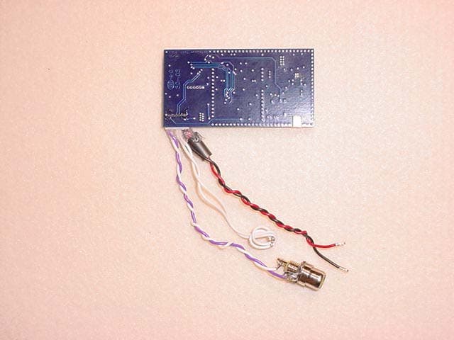
5015 B.U. Bowman Drive Buford, GA 30518 USA Voice: 770-831-8048 Fax: 770-831-8598 Type Acceptance Test Report Wideband FM Audio/Video Transmit Module FCC ID: QN41500 FCC Rule Part: 90 ACS Report Number: 03-0091-90TA Manufacturer: Datawave Model: Datawave1500 Internal Photographs 5015 B.U. Bowman Drive Buford, GA 30518 USA Voice: 770-831-8048 Fax: 770-831-8598 Figure 1: PCB – Top View 5015 B.U. Bowman Drive Buford, GA 30518 USA Voice: 770-831-8048 Fax: 770-831-8598 Figure 2: PCB – Bottom View
Operational Description
5015 B.U. Bowman Drive Buford, GA 30518 USA Voice: 770-831-8048 Fax: 770-831-8598 Type Acceptance Test Report Wideband FM Audio/Video Transmit Module FCC ID: QN41500 FCC Rule Part: 90 ACS Report Number: 03-0091-90TA Manufacturer: Datawave Model: Datawave1500 Theory of Operation 5015 B.U. Bowman Drive Buford, GA 30518 USA Voice: 770-831-8048 Fax: 770-831-8598 Video Signal Conditioning Audio inter- carrier modulator Modulator 5.5MHz (120 kHz BW) PA Video in Audio in Antenna Composite Baseband Information CCIR-405 Pre-emphasized Level Adjusted video FM inter-carrier @ 5.5MHz 75usec audio pre-emphasis AC baseband summing RF Signal Adjustable Power Output Theory of Operation This module transmits NTSC/PAL video and 1Vp-p audio signals using a standard wideband frequency modulation method. The module consists of 4 blocks for the transmission of audio/video at 2.4GHz: Figure 1 Transmitter Block Diagram Block Diagram Description The Video Signal Conditioning portion of the transmitter is used to add video pre-emphasis and divide down the incoming video level to provide an adjustable deviation constant for a desired bandwidth. The Audio Inter-Carrier Modulator block takes a 1Vp-p audio signal and adds pre-emphasis before it is applied to a 5.5MHz voltage controlled oscillator (VCO). The result of the circuit is a 5.5MHz inter-carrier signal with a deviation of ±60KHz. The two conditioned signals are then AC summed together and applied to the modulation input of the Modulator block. The Modulator block consists of an RF VCO, synthesizer and reference crystal. The synthesizer is programmed by a microcontroller which controls which carrier frequency is selected by the user. The output of the Modulator is a frequency modulated carrier that consists of the video information and the audio inter-carrier sidebands, which are 5.5MHz away from the carrier. The FM signal is then sent to the PA block which consists of a pre-amplifier and a power amplifier whose power output can be adjusted from 1mW to 300mW. The output of the PA block is fed to a frequency trap to reduce the 1 st and 2 nd harmonics of the carrier and then routed to the antenna port.
Parts List/Tune Up Info
DataWave Technologies, LLC • 190 Stanley Court • Lawrenceville, GA 30045 Voice: 678-442-1234 • FAX 678-442-1295 • www.datawavetechnologies.com 1 Factory Tuning Procedure 1. Power on transmitter and set to channel 1 operating frequency. 2. Adjust the output power to 300mW using R23. The current draw at 300mW should be around 500mA +/- 50mA. 3. Verify sub-carrier presence and adjust carrier offset by adjusting L2. The offset should be 5.5MHz. 4. Adjust deviation constant by adjusting R1 and measuring the level of video at C8. The proper deviation constant is reached when the peak to peak amplitude of video is .25V. 5. Sweep frequencies from 10MHz to Carrier noting signals exceeding 46dBuV. Make any repairs if necessary. Record any levels within 6dB of limit. 6. Verify 1 st and 2 nd Harmonic levels not to exceed -39.2dBc. Make any repairs if necessary. Record any levels within 6dB of limit. 7. Repeat Steps 4 and 5 for channel 2 operation as well.
RF Exposure Info
ACS Report: 03-0091-90TA Page 1 Type Acceptance Test Report Wideband FM Audio/Video Transmit Module FCC ID: QN41500 FCC Rule Part: 90 ACS Report Number: 03-0091-90TA Manufacturer: Datawave Model: Datawave1500 RF Exposure Information Model: Datawave 1500 Advanced Compliance Solutions FCC ID: Q4N1500 ACS Report: 03-0091-90TA Page 2 General Information: Applicant: Datawave Technologies ACS Project: 03-0091 FCC ID: Q4N1500 Device Category: Fixed Mount Environment: General Population/Uncontrolled Exposure Technical Information: Antenna Type: Integrated folded dipole and External Patch Antenna Gain: 0 dBi Transmitter Conducted Power: 26.2dBm or 416.87mW Maximum System EIRP: 26.2dBm or 416.87mW Operating Configuration: Pole Mounted Exposure Conditions: Greater than 20cm from the population MPE Calculation The minimum separation distance is calculated as follows: E(V/m) = xPxG30 Power Density: P d =(mW/cm 2 ) = d MPE Distance MPE Limits for General Population/Uncontrolled Exposure Radio Power Antenna Gain Sytem EIRP MPE Limit MPE Distance (dBm) (dBi) (mW) (mW/cm2)(cm) 26.2 10 4168.69 1.00 18.21 Installation Guidelines The installation manual contains the following text advising how to install the equipment to maintain compliance with the FCC RF exposure requirements: Conclusion This device complies with the MPE requirements by providing adequate separation between the device, any radiating structure and the general population. Warning: All original equipment manufacturers (OEM) integrating this device within their products must maintain a minimum distance of 20cm between the installed antenna and the user or general population. For applications requiring handheld or body worn operations OEMS must submit their product to the FCC for Specific Absorption Rate (SAR) testing. E 2 3770
RF Exposure Info
Radio RF Safety Calculator Interpretation of Results 1. Remember that the power value entered into these calculations should be the average power seen at the antenna, and not Peak Envelope Power (PEP). You may also consider feedline loss in calculating your average power at the antenna. 2. If you wish to estimate the power density at a point below the main lobe of a directional antenna, and if the antenna's vertical pattern is known, recalculate using the antenna's gain in the relevant direction. 3. Please also consult FCC OET Bulletin 65. It contains a thorough discussion of the RF Safety regulations as they apply to exposure limits and contains numerous charts, tables, worksheets, and other data to help determine station compliance. Calculation Results Average Power at the Antenna 0.417 watts Antenna Gain in dBi 10.00 dBi Distance to the Area of Interest 0.66 feet Frequency of Operation 2400.000 MHz Are Ground Reflections Calculated? No Estimated RF Power Density 0.8200 mw/cm 2 Controlled Environment Uncontrolled Environment Maximum Permissible Exposure (MPE) 5.00 mw/cm 2 1.00 mw/cm 2 Distance to Compliance From Center of Antenna 0.32 feet 0.65 feet Does the Area of Interest Appear to be in Compliance? yes yes approx 10dBi for compliance at 417 mWatts and 2400 MHz @ 20cm.
Test Report
5015 B.U. Bowman Drive Buford, GA 30518 USA Voice: 770-831-8048 Fax: 770-831-8598 Type Acceptance Test Report Wideband FM Audio/Video Transmit Module FCC ID: QN41500 FCC Rule Part: 90 ACS Report Number: 03-0091-90TA Manufacturer: Datawave Technologies Model: 1500-2467-33 Test Begin Date: April 25, 2003 Test End Date: May 6, 2003 Report Issue Date: May 28, 2003 Prepared by: Reviewed by: R. Sam Wismer Engineering Manager ACS, Inc. Richard Bianco EMI/EMC Approvals Engineer ACS, Inc. This test report shall not be reproduced except in full. This report may be reproduced in part with prior written consent of ACS, Inc. The results contained in this report are representative of the sample(s) submitted for evaluation. This report contains 13 pages Table of Contents 1.0 General 3 1.1 Introduction 3 1.2 Product Description 3 1.2.1 Intended Use 3 1.2.2 Technical Specifications 3 2.0 Location of Test Facility 3 2.1 Description of Test Facility 4 2.1.2 Open Area Test Site 4 2.1.2 Conducted Emissions Test Site 5 3.0 Applicable Standards and References 6 4.0 List of Test Equipment 7 5.0 EUT Setup Block Diagram 8 6.0 Summary of Tests 9 6.1 Section 15.207 - Power Line Conducted Emissions 9 6.1.1 Test Methodology 9 6.1.2 Test Results 9 6.2 Section 15.209 - Radiated Emissions (Unintentional Radiation) 10 6.2.1 Test Methodology 10 6.2.2 Test Results 10 6.3 Sections 2.1046 & 90.205 – Peak Output Power 10 6.3.1 Test Methodology 10 6.3.2 Test Results 11 6.4 Section 2.1049, 90.208 & 90.210 11 6.3.1 Test Methodology 12 6.3.2 Test Results 12 6.5 Section 90.210 - Spurious Emissions 12 6.5.1 Section 2.1051 & 90.210 - RF Conducted Spurious Emissions 12 6.5.1.1 Test Methodology 12 6.5.1.2 Test Results 12 6.5.2 Section 2.1053 & 90.210 - Radiated Spurious Emissions 12 6.5.2.1 Test Methodology 12 6.5.2.2 Test Results 12 6.6 Section 2.1055 & 90.213 - Frequency Stability 12 6.6.1 Temperature 12 6.6.1.1 Test Methodology 12 6.6.1.2 Test Results 12 6.6.2 Voltage 12 6.6.2.1 Test Methodology 12 6.6.2.2 Test Results 12 7.0 CONCLUSION 13 Additional Exhibits Included In Filing Data Plots Internal Photographs External Photographs Test Setup Photographs Product Labeling RF Exposure – MPE Calculations Technical Documentation Installation/Users Guide Theory of Operation and System Block Diagram Model: 1500-2467-33 FCC ID: Q4N1500 ACS Report: 03-0091-90TA Advanced Compliance Solutions Page 3 1.0 GENERAL 1.1 Introduction The purpose of this report is to demonstrate compliance with the relevant portions of Parts 2, 15 and 90 of the FCC’s Code of Federal Regulations. 1.2 Product Description The EUT is a 2.4GHz 300mW Part 90 Wideband FM Audio/Video Transmit Radio Module. Detailed photographs of the EUT are filed separately with this filing. 1.2.1 Intended Use The Datawave 1500-2467-33 module is intended to be marketed to Original Equipment Manufacturer’s (OEM’s) as an approved audio, video radio module for integration into their devices. 1.2.2 Technical Specifications Table 1.2.2-1: Specifications Specification Parameter Min Typ Max UnitCondition Operating Voltage 4.85 5 5.15 Volts Regulated Curent Consumption 485 510 535 mA Pout=300mW Max RF Output Power 285 300 315 m W Carrier Power RF Bandwidth 7.75 8 8.25 MHz First Harmonic Rej. -57 -60 -65 dBc Reference to Carrier Power Frequency Range 2450 2483 MHz Channel 1 2458 MHz Channel 2 2474 MHz RF Power Output 1 300 m W Operating Temp. -40 85 ºC Modulation Type Frequency Modulation Dimensions Antenna Interface MMCX **see approved antenna listing Weight 3 oz VSWR Antenna Port 2:1 @ 50? 2.0 LOCATION OF TEST FACILTY All testing was performed by qualified ACS personnel located at the following address: ACS, Inc. 5015 B.U. Bowman Drive Buford, GA 30518 Model: 1500-2467-33 FCC ID: Q4N1500 ACS Report: 03-0091-90TA Advanced Compliance Solutions Page 4 2.1 DESCRIPTION OF TEST FACILITY Both the Open Area Test Site(OATS) and Conducted Emissions site have been fully described, submitted to, and accepted by the FCC, Industry Canada and the Japanese Voluntary Control Council for Interference by information technology equipment. The following certification numbers have been issued in recognition of these accreditations and certifications: FCC Registration Number: 89450 Industry Canada Lab Code: IC 4175 VCCI Member Number: 1831 VCCI OATS Registration Number R-1526 VCCI Conducted Emissions Site Registration Number: C-1608 2.1.1 Open Area Test Site The open area test site consists of a 40’ x 66’ concrete pad covered with a perforated electro-plated galvanized sheet metal. The perforations in the sheet metal are 1/8” holes that are staggered every 3/16”. The individual sheets are placed to overlap each other by 1/4” and are riveted together to provide a continuous seam. Rivets are spaced every 3” in a 3 x 20 meter perimeter around the antenna mast and EUT area. Rivets in the remaining area are spaced as necessary to properly secure the ground plane and maintain the electrical continuity. The entire ground plane extends 12’ beyond the turntable edge and 16’ beyond the antenna mast when set to a 10 meter measurement distance. The ground plane is grounded via 4 - 8’ copper ground rods, each installed at a corner of the ground plane and bound to the ground plane using 3/4" stainless steel braided cable. The turntable is an all aluminum 10’ flush mounted table installed in an all aluminum frame. The table is remotely operated from inside the control room located 40’ from the range. The turntable is electrically bonded to the surrounding ground plane via steel fingers installed on the edge of the turn table. The steel fingers make constant contact with the ground plane during operation. Adjacent to the turntable is a 7’ x 7’ square and 4’ deep concrete pit used for support equipment if necessary. The pit is equipped with 5 - 4” PVC chases from the pit to the control room that allow for cabling to the EUT if necessary. The underside of the turntable can be accessed from the pit so cables can be supplied to the EUT…
Text truncated - open the document above for the full version.
Test Report
5015 B.U. Bowman Drive Buford, GA 30518 USA Voice: 770-831-8048 Fax: 770-831-8598 Type Acceptance Test Report Wideband FM Audio/Video Transmit Module FCC ID: QN41500 FCC Rule Part: 90 ACS Report Number: 03-0091-90TA Manufacturer: Datawave Model: Datawave1500 Data Plots
Contact Information
Applicant
Gabriel G Abreo(Senior Design Engineer)
Test Firm
Advanced Compliance Solutions, Inc.Sam Wismer
Technical Specifications
| # | Rule Parts | Frequency Range | Power Output | Emission | Tolerance |
|---|---|---|---|---|---|
| 1 | 90 | 2.46 GHz - 2.47 GHz | 417.00 mW | 8M00F8W | 2.0000000000 ppm |
Other Applications from DataWave Technologies LLC
Q4NM1700
Oct 23, 2003WIDEBAND 2.4GHz AUDIO / VIDEO TRANSMITTER
Equipment Class
TNB - Licensed Non-Broadcast Station Transmitter