Q4NM1700WIDEBAND 2.4GHz AUDIO / VIDEO TRANSMITTER
DataWave Technologies LLC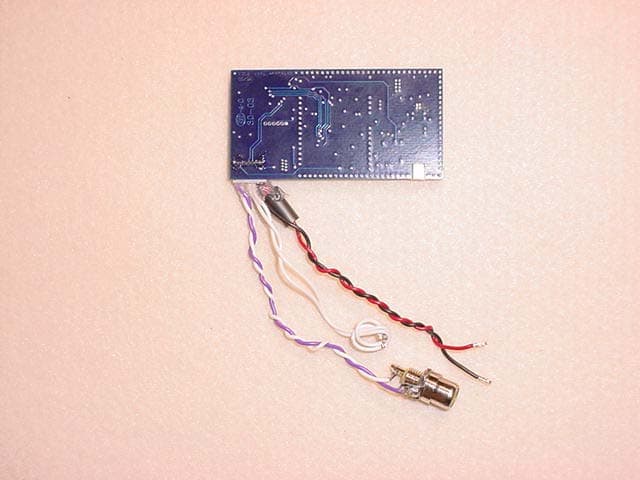
Click to zoom
Application Details
- Equipment Class
- TNB - Licensed Non-Broadcast Station Transmitter
- Date of Grant
- Oct 23, 2003
- Application Purpose
- Original Equipment
- Date of Application
- Oct 23, 2003
- Equipment Note
- WIDEBAND 2.4GHz AUDIO / VIDEO TRANSMITTER
- Frequency Range
- 2458.00000000 - 2474.00000000
- Company
- DataWave Technologies LLC
- Country
- United States
Documents & Files
Document Text
Text extracted from the exhibit documents filed with the FCC. Open a document above to read the original.
Users Manual
M1700 User’s Manual Release Date: 10/15/2003 Document # UM-M1700-1-91603 © 2003 Datawave Technologies, LLC 1 ww M1700 Ultra High Power FM Video Transmitter User’s Manual Revision A Oct 2003 M1700 User’s Manual Release Date: 10/15/2003 Document # UM-M1700-1-91603 © 2003 Datawave Technologies, LLC 2 1.0 Document Information .......................................................................................... 3 1.1 Copyright Information........................................................................................ 3 1.2 Revision Listing................................................................................................. 3 1.3 Agency Approval............................................................................................... 3 2.0 FCC Labeling and Documentation........................................................................ 4 2.1 FCC Notice ....................................................................................................... 4 2.2 Antenna Notice ................................................................................................. 4 2.3 Antenna Listing ................................................................................................. 5 2.4 FCC Labeling .................................................................................................... 5 2.5 RF Exposure ..................................................................................................... 5 3.0 Overview.............................................................................................................. 7 3.1 Introduction....................................................................................................... 7 3.2 Applications....................................................................................................... 7 4.0 Electrical Specifications ........................................................................................ 8 4.1 Electrical Characteristics................................................................................... 8 4.2 Power Requirements ........................................................................................ 8 4.3 Antenna port Impedance................................................................................... 9 5.0 Operation............................................................................................................ 10 5.1 Module Connections....................................................................................... 10 5.2 Integration and EMC Issues............................................................................ 10 5.3 Interconnection and Wiring ............................................................................. 10 5.4 Proximity and Cavity Effects ........................................................................... 11 5.5 Standard and Non-Standard Video Signals.................................................... 11 6.0 Transmitter Adjustments..................................................................................... 12 6.1 Modulation Adjustment ................................................................................... 12 6.2 RF Power Output Adjustment......................................................................... 14 7.0 Channel Selection and Programming ................................................................. 16 7.1 Channel Selection ........................................................................................... 16 7.2 RS-232 Programming ..................................................................................... 17 7.3 Transmitter Status........................................................................................... 18 7.4 Command String Examples ............................................................................ 19 7.5 Software Interface........................................................................................... 20 7.6 Operating Modes............................................................................................ 21 8.0 Hardware Interface ............................................................................................. 22 M1700 User’s Manual Release Date: 10/15/2003 Document # UM-M1700-1-91603 © 2003 Datawave Technologies, LLC 3 1.0 Document Information 1.1 Copyright Information All information within this manual is copyrighted and all rights are reserved by Datawave Technologies, LLC. Copying, duplicating, selling, or otherwise distributing any part of this product without the prior consent of an authorized representative of Datawave Technologies, LLC is prohibited. 1.2 Revision Listing Revision Number Description 1.00 Initial Release Table 1 1.3 Agency Approval Identification Agency Q4N1700 US- FCC Table 2 M1700 User’s Manual Release Date: 10/15/2003 Document # UM-M1700-1-91603 © 2003 Datawave Technologies, LLC 4 Warning: This product complies with Part 15 of the FCC Rules. Operation is subject to the following two conditions: (1) The device may not cause harmful interference and (2) This device must accept any interference received, including interference that may cause undesired operation. Warning: NOTE: This equipment has been tested and found to comply with the limits for a Class B digital device, pursuant to Part 15 of the FCC Rules. These limits are designed to provide reasonable protection against harmful interference in a residential installation. This equipment generates, uses, and can radiate radio frequency energy, and if not installed and used in accordance with the instructions, may cause harmful interference to radio communications. However, there is no guarantee that interference will not occur in a particular installation. If this equipment does cause harmful interference to radio or television reception, which can be determined by turning the equipment off and on, the user is encouraged to try to correct the interference by one or more of…
Text truncated - open the document above for the full version.
Cover Letter(s)
Correspondence Summary Q & A October 23, 2003 SUBJECT: DATAWAVE TECHNOLOGIES - FCC ID: Q4NM1700 TCB Question: Form 731: Please, provide the frequency tolerance and emission designator according to the measurement data in the test report. (Notes: The necessary bandwidth is to be calculated using the Carson’s rules according to Part 2. and the measurement data per Part 2.1047 (a)(b), and (d)) Applicant Answer: Item 6 The peak deviation frequency is 4MHz and the modulating frequency is 4.42MHz. Carson rule for necessary bandwidth is given below: Bn = 2M+2D Where: Bn = Necessary Bandwidth M = the modulation frequency: 4.42MHz in this case D = the deviation frequency: 4MHz in the case Therefore: Bn = 2(4 + 4.42) = 16.84MHz Emission Designator: 16M8F87 A new Form 731 has been uploaded with the correct designator. TIMCO ENGINEERING INC. 849 NW State Road 45 Newberry, Florida 32669 http://www.timcoengr.com 888.472.2424 F 352.472.2030 [email protected]
External Photos
5015 B.U. Bowman Drive Buford, GA 30518 USA Voice: 770-831-8048 Fax: 770-831-8598 Type Acceptance Test Report Wideband FM Video Transmit Module FCC ID: Q4NM1700 FCC Rule Part: 90 ACS Report Number: 03-0168-90TA Manufacturer: Datawave Model: Datawave M1700 External Photographs 5015 B.U. Bowman Drive Buford, GA 30518 USA Voice: 770-831-8048 Fax: 770-831-8598 Figure 1: Top View 5015 B.U. Bowman Drive Buford, GA 30518 USA Voice: 770-831-8048 Fax: 770-831-8598 Figure 2: Bottom View
ID Label/Location Info
5015 B.U. Bowman Drive Buford, GA 30518 USA Voice: 770-831-8048 Fax: 770-831-8598 Type Acceptance Test Report Wideband FM Video Transmit Module FCC ID: Q4NM1700 FCC Rule Part: 90 ACS Report Number: 03-0168-90TA Manufacturer: Datawave Model: Datawave M1700 Label Information 5015 B.U. Bowman Drive Buford, GA 30518 USA Voice: 770-831-8048 Fax: 770-831-8598 The FCC label is placed over the lid with a type of tamper resistant label that automatically tears if it is removed. FCCID: Q4NM1700 This device complies with Part 15 of the FCC Rules. Operation is subject to the following two conditions. (1) This device may not cause harmful interference, and (2) this device must accept any interference received, including interference that may cause undesired o peration.
Internal Photos
5015 B.U. Bowman Drive Buford, GA 30518 USA Voice: 770-831-8048 Fax: 770-831-8598 Type Acceptance Test Report Wideband FM Video Transmit Module FCC ID: Q4NM1700 FCC Rule Part: 90 ACS Report Number: 03-0168-90TA Manufacturer: Datawave Model: Datawave M1700 Internal Photographs 5015 B.U. Bowman Drive Buford, GA 30518 USA Voice: 770-831-8048 Fax: 770-831-8598 Figure 1: PCB – Top View 5015 B.U. Bowman Drive Buford, GA 30518 USA Voice: 770-831-8048 Fax: 770-831-8598 Figure 2: PCB – Bottom View
Operational Description
5015 B.U. Bowman Drive Buford, GA 30518 USA Voice: 770-831-8048 Fax: 770-831-8598 Type Acceptance Test Report Wideband FM Video Transmit Module FCC ID: Q4NM1700 FCC Rule Part: 90 ACS Report Number: 03-0168-90TA Manufacturer: Datawave Model: Datawave M1700 Theory of Operation 5015 B.U. Bowman Drive Buford, GA 30518 USA Voice: 770-831-8048 Fax: 770-831-8598 Video Signal Conditioning Modulator PA Video in Antenna Composite Baseband Information CCIR-405 Pre-emphasized Level Adjusted video RF Signal Adjustable Power Output Theory of Operation This module transmits NTSC/PAL video and 1Vp-p audio signals using a standard wideband frequency modulation method. The module consists of 3 blocks for the transmission of audio/video at 2.4GHz: Figure 1 Transmitter Block Diagram Block Diagram Description The Video Signal Conditioning portion of the transmitter is used to add video pre-emphasis and divide down the incoming video level to provide an adjustable deviation constant for a desired bandwidth. The Audio Inter-Carrier Modulator block takes a 1Vp-p audio signal and adds pre-emphasis before it is applied to the modulation input of the Modulator block. The Modulator block consists of an RF VCO, synthesizer and reference crystal. The synthesizer is programmed by a microcontroller which controls which carrier frequency is selected by the user. The output of the Modulator is a frequency modulated carrier. The FM signal is then sent to the PA block which consists of a pre-amplifier and a power amplifier whose power output can be adjusted from 1mW to 1000mW. The output of the PA block is fed to a frequency trap to reduce the 1 st and 2 nd harmonics of the carrier and then routed to the antenna port.
Parts List/Tune Up Info
Setup Procedure for Production The following steps are required for proper setup and operation of the M1700. 1.0 Modulation Adjustment Transmitter modulation adjustments are required when non-standard video signals are transmitted. Figure 9 shows a video signal (with averaging on) that contains NTSC standard timing but non-standard video levels. The red line marker shows a .34Vdc shift for blanking, and sync tip amplitude is only .18Vdc as indicated by the blue line marker. In order to maintain proper video scaling between sync tip and maximum video level the maximum peak to peak voltage of video would be .64V. Any voltage over this value would result in an over-white condition and over- modulation would occur which would result in white streaks or tearing in the video image. Figure 1 Non-Standard Video Level Output The M1700 modulation circuit is based off of a monolithic VCO with a tuning sensitivity of 140MHz/V. Through software and passive circuit design the tuning sensitivity is reduced to about 25MHz/V. That means that .1V over a .64Vp-p video signal will change the RF bandwidth from 8MHz to 10.5MHz. Since the receiver is set for an 8MHz RF channel you will lose the modulated video information that exists outside this 8MHz channel. The result will be white steaks or tearing in video when over- modulation 1 is present. To adjust the modulation level to accommodate the video signal in Figure 9, you will need the following items. 1. Function generator capable of a DC offset square wave at 1.5 KHz. 2. Oscilloscope capable of viewing line video information. 3. Spectrum Analyzer with a RBW of 30kHz and capable of measuring an RF signal up to 2.5GHz Step1 Setup the function generator to output a 1.5 KHz .64Vp-p square wave and add a plus .34Vdc shift. Step2 Power up the transmitter and apply the test signal to the video input port of the transmitter. Be mindful of the impedance mismatch possibility between the function generator and the video port on the transmitter. If there is a mismatch you will need to adjust the amplitude of the test signal back to .64Vp-p. Step3 Using a spectrum analyzer measure the deviation from the nominal carrier frequency and adjust this deviation until you have a deviation of .5 MHz. At this point all that is left is to apply the actual signal in Figure 9 to test the adjustment and you’re done. Verifying this measurement insures that the spectral mask is within the limitations defined by Part 90 of the FCC Rules and Regulations (Fig. 11). Failure to do so will void the transmitter’s FCC compliance and it will be unlawful to operate the unit in the United States. For situations where the above mentioned test equipment is not available and jurisdiction allows, simple comparative measurements can be made between non-transmitted and transmitted images. 1 Over-modulation in FM occurs when the deviation exceeds the maximum allowable for the desired RF channel. As a baseline, apply the video signal of the target video source directly to a display device and carefully observe the image in terms of resolution and brightness. Next, apply the video source to the transmitter and observe the received video image and adjust the modulation input until the received image matches the baseline image in resolution and brightness. Typically, attention is given to the brightness level as this is what is affected most by non-standard video levels. Once the modulation level is adjusted for a matching picture a “black to white” test needs to be performed in order to insure that an over-white condition does not tear the video image. “White streaks” in the image usually is a result of over- modulation. “Black streaks” or “a dim image” can be attributed to under- modulation 2 . Moving a soldering iron in and out of the scene several times works well for this test. The image should not tear upon white out. If it does, continue to adjust the modulation level until the over-modulation or under-modulation condition stops. It should be made aware that this is an approximate method for setting the deviation level of the transmitter and is subject to the display device, FM receiver and video source levels being known good constants if this is to become the chosen method of adjustment for production. This procedure is not recommended for transmitters being used in the United States and doing so will void FCC compliance. 1.1 RF Power Output Adjustment The M1700 is adjustable for power levels from 1mW up to 1000mW. The adjustment can be achieved by manually rotating the adjustment potentiometer. It is important to remember that increasing the RF power output also increase the power required to operate the transmitter and careful consideration should be given to the power supply circuits selected. Please refer to Section 4.2 for more information. 2 Under-modulation in FM occurs when the maximum deviation is 20% or more below the maximum allowable for the desired RF channel.
RF Exposure Info
ACS Report: 03-0168-90TA Page 1 Type Acceptance Test Report Wideband FM Video Transmit Module FCC ID: Q4NM1700 FCC Rule Part: 90 ACS Report Number: 03-0168-90TA Manufacturer: Datawave Model: Datawave M1700 RF Exposure Information Model: Datawave M1700 Advanced Compliance Solutions FCC ID: Q4NM1700 ACS Report: 03-0168-90TA Page 2 General Information: Applicant: Datawave Technologies ACS Project: 03-0168 FCC ID: Q4NM1700 Device Category: Mobile Environment: General Population/Uncontrolled Exposure Technical Information: Antenna Type: Integrated folded dipole and External Patch Antenna Gain: 0 dBi Transmitter Conducted Power: 29.4dBm or 870.96mW Maximum System EIRP: 29.4dBm or 870.96mW Operating Configuration: Intended for integration into various mobile devices Exposure Conditions: Greater than 20cm from the population MPE Calculation The minimum separation distance is calculated as follows: E(V/m) = xPxG30 Power Density: P d =(mW/cm 2 ) = d MPE Distance Transmit Freq. Radio Power Power Radio Power Antenna Gain MPE Distance (MHz) (dBm) Density (mW) (dBi) (cm) (mW/Cm2) 2458 29.4 1.00 0.87 7 18.6376 Installation Guidelines The installation manual contains the following text advising how to install the equipment to maintain compliance with the FCC RF exposure requirements: Conclusion This device complies with the MPE requirements by providing adequate separation between the device, any radiating structure and the general population. Warning: All original equipment manufacturers (OEM) integrating this device within their products must maintain a minimum distance of 20cm between the installed antenna and the user or general population. For applications requiring handheld or body worn operations OEMS must submit their product to the FCC for Specific Absorption Rate (SAR) testing. E 2 3770
Test Report
5015 B.U. Bowman Drive Buford, GA 30518 USA Voice: 770-831-8048 Fax: 770-831-8598 Type Acceptance Test Report Wideband FM Video Transmit Module FCC ID: Q4NM1700 FCC Rule Part: 90 ACS Report Number: 03-0168-90TA Manufacturer: Datawave Model: Datawave M1700 Data Plots 5015 B.U. Bowman Drive Buford, GA 30518 USA Voice: 770-831-8048 Fax: 770-831-8598 ANTENNA CONDUCTED SPURIOUS EMISSIONS
Test Report
RF2163 Current vs Power Out Pin=13.5dBm 0.00 0.10 0.20 0.30 0.40 0.50 0.60 0.70 0.80 0.90 222324252627282930 Pout (dBm) Icc (A) Current @ 3.3V Figure 1: Current vs. Power Out at 3.3 volts at the final amplifer stage
Test Report
Enter ACS Project #: 03-0168 Enter Test Date: 9/11/2003 Enter Technician Name: H Orozco Enter Manufacturer: Datawave Enter EUT Name: M1700 RF Output Power(dBm): 25.5 RF Output Power ( Watts ) : 0.355 Frequency (MHz) Generator Level(dBm) Cable Attenuation(d B) Antenna Gain(dB) Corrected Reading(dBm) Substitution Field Strength(dBc) Limit (dBc) Margin(dB) Notes 4949 -26.00 -1.21 9.80 -14.99 -40.49 -38.50 1.99 HC 7424 -40.00 -1.50 11.10 -27.40 -52.90 -38.50 14.40 HC 9896 -40.00 -1.74 11.80 -26.46 -51.96 -38.50 13.46 HC 12370 -70.00 -1.89 12.80 -55.31 -80.81 -38.50 42.31 HC 0.00 -25.50 -38.50 -13.00 4913.9 -30.00 -1.21 9.80 -18.99 -44.49 -38.50 5.99 LC 7376 -44.00 -1.50 11.10 -31.40 -56.90 -38.50 18.40 LC 9837 -36.00 -1.74 11.80 -22.46 -47.96 -38.50 9.46 LC 12295 -70.00 -1.89 12.80 -55.31 -80.81 -38.50 42.31 LC 0.00 -25.50 -38.50 -13.00 0.00 -25.50 -38.50 -13.00 6) In Accordance with TIA 603-A 7)2)3)4) Substitution Field Strength Measurement Data Sheet Test Data Sheet Version 1.0 Notes 1) Enter ACS Project #: 03-0168 Enter Test Date: 9/11/2003 Enter Technician Name: H Orozco Enter Manufacturer: Datawave Enter EUT Name: M1700 RF Output Power(dBm): 29 RF Output Power ( Watts ) : 0.794 Frequency (MHz) Generator Level(dBm) Cable Attenuation(d B) Antenna Gain(dB) Corrected Reading(dBm) Substitution Field Strength(dBc) Limit (dBc) Margin(dB) Notes 4949 -26.00 -1.21 9.80 -14.99 -43.99 -42.00 1.99 HC 7424 -40.00 -1.50 11.10 -27.40 -56.40 -42.00 14.40 HC 9896 -40.00 -1.74 11.80 -26.46 -55.46 -42.00 13.46 HC 12370 -70.00 -1.89 12.80 -55.31 -84.31 -42.00 42.31 HC 0.00 -29.00 -42.00 -13.00 4913.9 -30.00 -1.21 9.80 -18.99 -47.99 -42.00 5.99 LC 7376 -44.00 -1.50 11.10 -31.40 -60.40 -42.00 18.40 LC 9837 -36.00 -1.74 11.80 -22.46 -51.46 -42.00 9.46 LC 12295 -70.00 -1.89 12.80 -55.31 -84.31 -42.00 42.31 LC 0.00 -29.00 -42.00 -13.00 0.00 -29.00 -42.00 -13.00 6) In Accordance with TIA 603-A 7)2)3)4) Substitution Field Strength Measurement Data Sheet Test Data Sheet Version 1.0 Notes 1) Enter ACS Project #: 03-0168 Enter Test Date: 9/11/2003 Enter Technician Name: H Orozco Enter Manufacturer: Datawave Enter EUT Name: M1700 RF Output Power(dBm): 29.5 RF Output Power ( Watts ) : 0.891 Frequency (MHz) Generator Level(dBm) Cable Attenuation(d B) Antenna Gain(dB) Corrected Reading(dBm) Substitution Field Strength(dBc) Limit (dBc) Margin(dB) Notes 4949 -26.00 -1.21 9.80 -14.99 -44.49 -42.50 1.99 HC 7424 -40.00 -1.50 11.10 -27.40 -56.90 -42.50 14.40 HC 9896 -40.00 -1.74 11.80 -26.46 -55.96 -42.50 13.46 HC 12370 -70.00 -1.89 12.80 -55.31 -84.81 -42.50 42.31 HC 0.00 -29.50 -42.50 -13.00 4913.9 -30.00 -1.21 9.80 -18.99 -48.49 -42.50 5.99 LC 7376 -44.00 -1.50 11.10 -31.40 -60.90 -42.50 18.40 LC 9837 -36.00 -1.74 11.80 -22.46 -51.96 -42.50 9.46 LC 12295 -70.00 -1.89 12.80 -55.31 -84.81 -42.50 42.31 LC 0.00 -29.50 -42.50 -13.00 0.00 -29.50 -42.50 -13.00 6) In Accordance with TIA 603-A 7)2)3)4) Substitution Field Strength Measurement Data Sheet Test Data Sheet Version 1.0 Notes 1)
Test Report
5015 B.U. Bowman Drive Buford, GA 30518 USA Voice: 770-831-8048 Fax: 770-831-8598 Type Acceptance Test Report Wideband FM Video Transmit Module FCC ID: Q4NM1700 FCC Rule Part: 90 ACS Report Number: 03-0168-90TA Manufacturer: Datawave Technologies Model: M1700 Test Begin Date: August 21, 2003 Test End Date: September 3, 2003 Report Issue Date: September 30, 2003 Prepared by: Reviewed by: Hernando Orozco EMI/EMC Approvals Engineer ACS, Inc. R. Sam Wismer Engineering Manager ACS, Inc. This test report shall not be reproduced except in full. This report may be reproduced in part with prior written consent of ACS, Inc. The results contained in this report are representative of the sample(s) submitted for evaluation. This report contains 13 pages Table of Contents 1.0 General 3 1.1 Introduction 3 1.2 Product Description 3 1.2.1 Intended Use 3 1.2.2 Technical Specifications 3 2.0 Location of Test Facility 3 2.1 Description of Test Facility 4 2.1.2 Open Area Test Site 4 2.1.2 Conducted Emissions Test Site 5 3.0 Applicable Standards and References 6 4.0 List of Test Equipment 7 5.0 EUT Setup Block Diagram 8 6.0 Summary of Tests 9 6.1 Section 15.207 - Power Line Conducted Emissions 9 6.1.1 Test Methodology 9 6.1.2 Test Results 9 6.2 Section 15.209 - Radiated Emissions (Unintentional Radiation) 10 6.2.1 Test Methodology 10 6.2.2 Test Results 10 6.3 Sections 2.1046 & 90.205 – Peak Output Power 10 6.3.1 Test Methodology 10 6.3.2 Test Results 11 6.4 Section 2.1049, 90.208 & 90.210 11 6.3.1 Test Methodology 12 6.3.2 Test Results 12 6.5 Section 90.210 - Spurious Emissions 12 6.5.1 Section 2.1051 & 90.210 - RF Conducted Spurious Emissions 12 6.5.1.1 Test Methodology 12 6.5.1.2 Test Results 12 6.5.2 Section 2.1053 & 90.210 - Radiated Spurious Emissions 12 6.5.2.1 Test Methodology 12 6.5.2.2 Test Results 12 6.6 Section 2.1055 & 90.213 - Frequency Stability 12 6.6.1 Temperature 12 6.6.1.1 Test Methodology 12 6.6.1.2 Test Results 12 6.6.2 Voltage 12 6.6.2.1 Test Methodology 12 6.6.2.2 Test Results 12 7.0 CONCLUSION 13 Additional Exhibits Included In Filing Data Plots Internal Photographs External Photographs Test Setup Photographs Product Labeling RF Exposure – MPE Calculations Schematics Parts List Installation/Users Guide Theory of Operation and System Block Diagram Model: M1700 FCC ID: Q4NM1700 ACS Report: 03-0168-90TA Advanced Compliance Solutions Page 3 1.0 GENERAL 1.1 Introduction The purpose of this report is to demonstrate compliance with the relevant portions of Parts 2, 15 and 90 of the FCC’s Code of Federal Regulations. 1.2 Product Description The EUT is a 2.4GHz 950-1000mW Part 90 Wideband FM Audio/Video Transmit Radio Module. Detailed photographs of the EUT are filed separately with this filing. 1.2.1 Intended Use The Datawave M1700 module is intended to be marketed to Original Equipment Manufacturer’s (OEM’s) as an approved audio, video radio module for integration into their devices. 1.2.2 Technical Specifications Table 1.2.2-1: Specifications Specification Parameter Min Typ Max UnitCondition Operating Voltage 8 12 16 Volts Curent Consumption 540 560 580 mA Pout=950-1000mW Max RF Output Power 750 m W ±50mW RF Bandwidth 7.75 8 8.25 MHz First Harmonic Rej. -57 -60 -65 dBc Reference to Carrier Power Frequency Range 2450 2483 MHz Channel 1 2458 MHz Channel 2 2474 MHz RF Power Output 1 300 m W ±50mW Operating Temp. -40 85 ºC Modulation Type Frequency Modulation Dimensions 2.5” X 1.4” x .25” Antenna Interface MMCX **see approved antenna listing Weight 3 oz VSWR Antenna Port 2:1 @ 50? 2.0 LOCATION OF TEST FACILTY All testing was performed by qualified ACS personnel located at the following address: ACS, Inc. 5015 B.U. Bowman Drive Buford, GA 30518 Model: M1700 FCC ID: Q4NM1700 ACS Report: 03-0168-90TA Advanced Compliance Solutions Page 4 2.1 DESCRIPTION OF TEST FACILITY Both the Open Area Test Site(OATS) and Conducted Emissions site have been fully described, submitted to, and accepted by the FCC, Industry Canada and the Japanese Voluntary Control Council for Interference by information technology equipment. The following certification numbers have been issued in recognition of these accreditations and certifications: FCC Registration Number: 89450 Industry Canada Lab Code: IC 4175 VCCI Member Number: 1831 VCCI OATS Registration Number R-1526 VCCI Conducted Emissions Site Registration Number: C-1608 2.1.1 Open Area Test Site The open area test site consists of a 40’ x 66’ concrete pad covered with a perforated electro-plated galvanized sheet metal. The perforations in the sheet metal are 1/8” holes that are staggered every 3/16”. The individual sheets are placed to overlap each other by 1/4” and are riveted together to provide a continuous seam. Rivets are spaced every 3” in a 3 x 20 meter perimeter around the antenna mast and EUT area. Rivets in the remaining area are spaced as necessary to properly secure the ground plane and maintain the electrical continuity. The entire ground plane extends 12’ beyond the turntable edge and 16’ beyond the antenna mast when set to a 10 meter measurement distance. The ground plane is grounded via 4 - 8’ copper ground rods, each installed at a corner of the ground plane and bound to the ground plane using 3/4" stainless steel braided cable. The turntable is an all aluminum 10’ flush mounted table installed in an all aluminum frame. The table is remotely operated from inside the control room located 40’ from the range. The turntable is electrically bonded to the surrounding ground plane via steel fingers installed on the edge of the turn table. The steel fingers make constant contact with the ground plane during operation. Adjacent to the turntable is a 7’ x 7’ square and 4’ deep concrete pit used for support equipment if necessary. The pit is equipped with 5 - 4” PVC chases from the pit to the control room that allow for cabling to the EUT if necessary. The underside of the turntable can be accessed from the pit so cables can be supplied to the EUT from the pit.…
Text truncated - open the document above for the full version.
Test Setup Photos
5015 B.U. Bowman Drive Buford, GA 30518 USA Voice: 770-831-8048 Fax: 770-831-8598 Type Acceptance Test Report Wideband FM Video Transmit Module FCC ID: Q4NM1700 FCC Rule Part: 90 ACS Report Number: 03-0168-90TA Manufacturer: Datawave Model: Datawave M1700 Setup Photographs 5015 B.U. Bowman Drive Buford, GA 30518 USA Voice: 770-831-8048 Fax: 770-831-8598 Figure 1: Radiated Emissions – Front View Figure 2: Radiated Emissions – Rear View 5015 B.U. Bowman Drive Buford, GA 30518 USA Voice: 770-831-8048 Fax: 770-831-8598 Figure 3: Substitution Field Strength – Front View Figure 4: Substitution Field Strength – Rear View
Contact Information
Applicant
Gabriel G Abreo(Senior Design Engineer)
Test Firm
Advanced Compliance Solutions, Inc.Sam Wismer
Technical Specifications
| # | Rule Parts | Frequency Range | Power Output | Emission | Tolerance |
|---|---|---|---|---|---|
| 1 | 90 | 2.46 GHz - 2.47 GHz | 871.00 mW | 16M8F8F | 1.9000000000 ppm |
Other Applications from DataWave Technologies LLC
Q4N1500
Jun 16, 2003Wideband 2.4GHz Audio/ Video Transmitter
Equipment Class
TNB - Licensed Non-Broadcast Station Transmitter