Q4VFS31-15CBooster
Fiber-Span LLC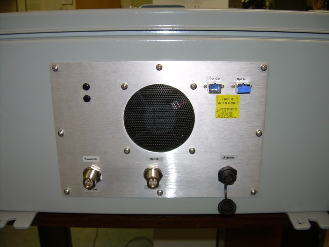
Click to zoom
Application Details
- Equipment Class
- TNB - Licensed Non-Broadcast Station Transmitter
- Date of Grant
- Jun 04, 2012
- Application Purpose
- Original Equipment
- Date of Application
- Jun 04, 2012
- Equipment Note
- Booster
- Frequency Range
- 169.00000000 - 175.00000000
- Company
- Fiber-Span LLC
- Country
- United States
Documents & Files
Document Text
Text extracted from the exhibit documents filed with the FCC. Open a document above to read the original.
Users Manual
3434 Rt. 22W ▪ Suite 140 Branchburg, NJ 08876 908.253.9080 ▪ fiber-span.com User Manual FS31R-15C VHF RRU 162 – 175 MHz Fiber-Fed Remote Repeater Unit (RRU) 4 Watts Linear Output Power Version 3 5/1/2012 3434 Rt. 22W ▪ Suite 140 Branchburg, NJ 08876 908.253.9080 ▪ fiber-span.com 1. Limitation of Liability Copyright 2011 Fiber-Span. All rights reserved. No part of this publication, or any software included with it may be reproduced, stored in a retrieval system, or transmitted in any form or by any means, including photocopying, electronic, mechanical, recording or otherwise, without the prior written permission of the copyright holder. Fiber-Span provides this document as is, without any warranty of any kind either expressed or implied including, but not limited to, the implied warranties of merchantability and fitness of a particular purpose. Fiber-Span may make changes or improvements in the equipment, software, or specifications described in this document at any time and without notice. These changes will be incorporated in new releases of this document. This document may contain technical inaccuracies or typographical errors. Fiber-Span waives responsibility for any labor, materials, or costs incurred by any person or party as a result of using this document. Fiber-Span and any of its affiliates shall not be liable for any damages (including, but not limited to, consequential, indirect or incidental, special damages or loss of profits or date) even if they were foreseeable and Fiber-Span has been informed of their potential occurrence, arising out of or in connection with this document or its use. Fiber-Span 3434 Route 22 W. Branchburg, New Jersey 08876 Tel: (908) 253-9080 Fax: (908) 253-9086 www.fiber-span.com 3434 Rt. 22W ▪ Suite 140 Branchburg, NJ 08876 908.253.9080 ▪ fiber-span.com -This page intentionally left blank- 1 3434 Rt. 22W ▪ Suite 140 Branchburg, NJ 08876 908.253.9080 ▪ fiber-span.com 2. Introduction The FS31R-15C Very High Frequency (VHF) Fiber Optic Remote Repeater Unit (FO-RRU) is a linear 4 Watts (36 dBm) RF power amplifier covering the frequency range from 162 to 175 MHz. The unit offers fiber input / output interface for long haul operation through a single mode fiber medium. Device improves in-building wireless coverage enhancement to eliminate dropped calls and poor reception by amplifying and re-broadcasting a cell tower signal throughout a building. While the fiber section is bandwidth unlimited, the internal RF components are optimized for best operation in the VHF bandwidth. RF has a separate input and output port to accommodate simplex application; however this product series can contain a duplexer for a bi-directional configuration ensuring uplink and downlink into a distributive antenna system (DAS). 3. Revision History Version Description Date Author 1 Draft release 5/1/2012 C.M. 2 Update FCC Statement 24-May-12 J.S. 3 Changed MPI distances to 1.5 and 2.5 meters 31-May-2012 J.S. 2 3434 Rt. 22W ▪ Suite 140 Branchburg, NJ 08876 908.253.9080 ▪ fiber-span.com 4. Table of Contents 1. Limitation of Liability............................................................................................................. 1 2. Introduction ............................................................................................................................. 1 3. Revision History ..................................................................................................................... 1 4. Table of Contents .................................................................................................................... 2 5. Warnings ................................................................................................................................. 4 6. Main Product Name ................................................................................................................ 5 7. Sub Product Name .................................................................................................................. 5 8. System Application ................................................................................................................. 6 9. Startup Checklist ..................................................................................................................... 7 10. Installation............................................................................................................................ 7 10.1. Connecting RF ............................................................................................................ 7 10.2. Mounting installation .................................................................................................. 8 11. Block Diagram ..................................................................................................................... 8 12. Specifications ....................................................................................................................... 9 12.1. Electrical ..................................................................................................................... 9 12.2. Mechanical ................................................................................................................ 11 Wall Mount Version ............................................................................................................. 11 Rack Mount Version ............................................................................................................. 11 12.3. Tools ......................................................................................................................... 11 12.4. On Site Requirements ............................................................................................... 12 13. General Precautions ........................................................................................................... 12 14. Maintenance ..............................................…
Text truncated - open the document above for the full version.
Cover Letter(s)
World Fiber Sp a 3434 Rt. 2 Branchbu Attn. Mr. H Re: Req u Please b e meet all o § 90.219 Licensee s signal boo (a) The am mobile, or system's n (b) Class limit the t o Class B b booster is (c) Class A narrowba meet the e (d) Class buildings, interferen (e) The li c Commiss rule requi (f) Licens e §90.7 are systems. be requir e Best reg a Michelle F Nemko US dwide Te an. LLC. 22W, Suite 14 rg, NJ 08876 Hal Halpem uirements for e informed tha of the requirem Use of sign s authorized t osters at fixed mplified signa r portable stat normal signal A narrowban otal effective broadband sig s designed to A narrowband nd channel th emission limit B broadband tunnels, und ce to other u s censee is give ion. Certificat rements are m ees employin responsible f Normal co-ch ed to resolve ards, Furrow SA esting an Nemko USA, Tel: +1 972 43 6 40 6 Booster ope r at the equipm ments of rule nal boosters. to operate rad d locations in al is retransm tion(s). The b l coverage ar d signal boo s radiated powe gnal boosters amplify. d boosters m hat the booste ts of §90.210 signal boost e erground are sers. en authority to ted equipmen met. g either Clas s for correcting hannel transm interference p nd Certi Inc. Dallas Divi 6-9600 Fax: +1 rating in CFR ment identified part 90.219 a dio systems in accordance w itted only on t booster will fill ea. sters must be er (ERP) of th are limited to ust meet the er is designed for frequenci ers are permi as, etc., or in o operate sign nt must be em s A narrowba any harmful missions will n problems purs ification ision 802 N. Ke 972 436-2667 47, Part 90 S with FCC ID as stated belo n the frequenc with the follow the exact freq in only weak equipped wit he unit to a m o 5 watts ERP out-of-band e d to amplify. C ies outside of itted to be use remote areas nal boosters w mployed and th and or Class B interference t not be conside suant to §90. n ealy, Lewisville, T Website: www.n Services .: Q4VFS31- 1 ow. cy bands ab o wing criteria: quency(ies) of k signal areas th automatic g maximum of 5 P for each aut emission limit Class B broad f the booster's ed only in con s, i.e., areas w without separ he licensee m B broadband that the equip ered as harmf 173(b). TX USA nemko.com 15C is a boos ove 150 MHz f the originati s and cannot e gain control c watts under a thorized frequ ts of §90.210 dband signal b s designed pa nfined or indo where there i rate authoriza must ensure th signal booste pment may ca ful interferenc ster and must may employ ng base, fixe d extend the circuitry which all conditions uency that the for each boosters mus assband. oor areas suc is little or no r ation from the hat all applica ers as defined ause to other ce. Licensees t d, h will . e st h as risk of e able d in s will
External Photos
Rev 1, Initial release, Rev by CM filename: fs31r-15c_rru external pictures Page 1/ 3 3434 Rt. 22W ▪ Suite 140 Branchburg, NJ 08876 908.253.9080 ▪ fiber-span.com EXTERNAL PICTURES I SOMETRIC VIEW T OP VIEW Rev 1, Initial release, Rev by CM filename: fs31r-15c_rru external pictures Page 2/ 3 3434 Rt. 22W ▪ Suite 140 Branchburg, NJ 08876 908.253.9080 ▪ fiber-span.com BOTTOM VIEW L EFT SIDE VIEW Rev 1, Initial release, Rev by CM filename: fs31r-15c_rru external pictures Page 3/ 3 3434 Rt. 22W ▪ Suite 140 Branchburg, NJ 08876 908.253.9080 ▪ fiber-span.com RIGHT SIDE VIEW
ID Label/Location Info
FS31R-15C FCC LABEL LOCATION Revision History Revision Description Date Author 1 Initial release 1/6/2012 CM Title: FS31R-15C, FCC_Label_Location Number: 285-0572-FCC-LBL-2 Rev 1 Page 1 3434 Rt. 22W ▪ Suite 140 Branchburg, NJ 08876 908.253.9080 ▪ fiber-span.com Rack Mount Version Rear View Affix FCC label at the left-edge and 3-3/8 inches on label center from the bottom corner of the unit. FCC Label Location depicted here in Green, actual color is White. FS31R-15C FCC LABEL LOCATION Revision History Revision Description Date Author 1 Initial release 1/6/2012 CM Title: FS31R-15C, FCC_Label_Location Number: 285-0572-FCC-LBL-2 Rev 1 Page 2 3434 Rt. 22W ▪ Suite 140 Branchburg, NJ 08876 908.253.9080 ▪ fiber-span.com Wall Mount Version Front View Affix FCC label just above the serial label 1.5 inches from the heatsink bottom edge. FCC Label Location depicted here in Green, actual color is White.
Parts List/Tune Up Info
FS31R-15C Tuning Procedure Rev1 Page 1 3434 Rt. 22W | Suite 140 | Branchburg, NJ 08876 908.253.9080 | fiber-span.com FS31R-15C Remote Repeater Unit Tuning Procedure Introduction The FS31R-15C Very High Frequency (VHF) fiber optic remote repeater unit is a 4 Watt linear fiber optic fed RF Remote Repeater Unit (RRU) for wide-area coverage extension applications. Device provides wireless signal coverage for VHF 2-way radio. General Test Practices and Assumptions 1. The RRU is pre-tuned at the factory and will not require frequency, or filter tuning performed. Only gain levels are settable by the user, “tuning” is the process of setting the RRU gain levels. 2. Tuning will be performed by trained Fiber-Span qualified RF personnel. 3. All the unused RRU RF ports are to be terminated with 50 Ohm load with appropriate RF power rating. 4. Verify that all the fiber optic cleaning procedures are adhered to while connecting fiber patch cords. 5. A Fiber-Span compatible Head End Fiber Transceiver Unit (FTU) as part of a Head End system will be used to set RRU levels. Tuning Procedure The RRU is controlled exclusively by software. Connectivity to the RRU control is through an Ethernet connection. This will be referred to as remote access commands. Let RRU be turned on to boot for two minutes. Downlink See Diagram for connection information. Before signals are applied, ensure that the RF PA on the downlink is muted and the Downlink RF attenuator is set to maximum attenuation using the appropriate remote access commands. Verify the source generator frequency to desired RF FS31R-15C Tuning Procedure Rev1 Page 2 3434 Rt. 22W | Suite 140 | Branchburg, NJ 08876 908.253.9080 | fiber-span.com frequency [169.5 to 173.5 MHz] and source generator RF level to -10 dBm. With remote access control, un-Mute the PA then decrease downlink attenuation to set the downlink RF output composite level to target. Do not set downlink composite RF level output greater than +34.5 dBm. Uplink See Diagram for connection information. Before signals are applied, ensure that the Uplink RF attenuator is set to maximum attenuation using the appropriate remote access commands. Verify the source generator frequency to desired RF frequency [162.5 to 166.5 MHz] and source generator RF level to -40 dBm (-70 dBm into the RRU). With remote access control, decrease uplink attenuation to set the uplink RF output level to -60dBm (Gain of 10 dB). Connections Diagram T R Fibers To RRU FTU Optical Transceivers RF Ethernet OMU Optical Multiplex Unit RF Attenuator 25W Spectrum Analyzer Signal Source 30 dB RRU Optical Fiber Downlink RF Cables Uplink RF Cables Neutral RF Cables
RF Exposure Info
Prediction of MPE limit at a given distance Equation from page 18 of OET Bulletin 65, Edition 97-01 where:S = power density P = power input to the antenna G = power gain of the antenna in the direction of interest relative to an isotropic radiator R = distance to the center of radiation of the antenna Maximum peak output power at antenna input terminal:36.0(dBm)* Maximum peak output power at antenna input terminal:3981(mW) Antenna gain(maximum):15(dBi)* Maximum antenna gain:31.6(numeric) Time Averaging:100(%)* Prediction distance:250(cm)* Prediction frequency:175(MHz)* MPE limit for uncontrolled exposure at prediction frequency:0.200(mW/cm^2) Power density at prediction frequency:0.160 (mW/cm^2) This equates to:1.603 W/m^2 2 4R PG S
Test Report
Nemko Test Report: 10215925RUS1 Applicant: Fiber-Span 3434 Rte. 22W Suite 140 Branchburg, NJ 08876 Equipment Under Test: FS31R-15C (E.U.T.) FCC ID.: Q4VFS31-15C In Accordance With: CFR 47 Part 90, Subpart I Private Land Mobile Repeater Tested By: Nemko USA Inc. 802 N. Kealy Lewisville, TX 75057-3136 TESTED BY: DATE: 03 April 2012 David Light, Senior Wireless Engineer APPROVED BY: DATE: 05 April 2012 Mike Cantwell Number of Pages: 26 Nemko USA, Inc. CFR 47 PART 90, SUBPART I PRIVATE LAND MOBILE REPEATER EQUIPMENT: FS31R-15C PROJECT NO.: 10215925RUS1 Page 2 of 26 Table of Contents Section 1. Summary of Test Results ......................................................................................... 3 Section 2. General Equipment Specification ............................................................................. 5 Section 3. RF Power Output ...................................................................................................... 7 Section 4. Occupied Bandwidth ................................................................................................ 8 Section 5. Spurious Emissions at Antenna Terminals ............................................................. 11 Section 6. Field Strength of Spurious Emissions .................................................................... 15 Section 7. Test Equipment List ................................................................................................ 16 ANNEX A - TEST METHODOLOGIES ....................................................................................... 17 ANNEX B - TEST DIAGRAMS .................................................................................................... 23 Nemko USA, Inc. CFR 47 PART 90, SUBPART I PRIVATE LAND MOBILE REPEATER EQUIPMENT: FS31R-15C PROJECT NO.: 10215925RUS1 Page 3 of 26 Section 1. Summary of Test Results Manufacturer: Fiber-Span Model No.: FS31R-15C Serial No.: A2811-1-1 General: All measurements are traceable to national standards. These tests were conducted on a sample of the equipment for the purpose of demonstrating compliance with CFR Part 90, Subpart I. New Submission Production Unit Class II Permissive Change Pre-Production Unit THIS TEST REPORT RELATES ONLY TO THE ITEM(S) TESTED. THE FOLLOWING DEVIATIONS FROM, ADDITIONS TO, OR EXCLUSIONS FROM THE TEST SPECIFICATIONS HAVE BEEN MADE. See “ Summary of Test Data”. This report must not be used to claim product certification, approval, or endorsement by NVLAP, NIST, or any agency of the Federal Government. Nemko USA, Inc. is a NVLAP accredited laboratory. Nemko USA Inc. authorizes the above named company to reproduce this report provided it is reproduced in its entirety and for use by the company’s employees only. Any use which a third party makes of this report, or any reliance on or decisions to be made based on it, are the responsibility of such third parties. Nemko USA Inc. accepts no responsibility for damages, if any, suffered by any third party as a result of decisions made or actions based on this report. This report applies only to the items tested. Nemko USA, Inc. CFR 47 PART 90, SUBPART I PRIVATE LAND MOBILE REPEATER EQUIPMENT: FS31R-15C PROJECT NO.: 10215925RUS1 Page 4 of 26 Summary Of Test Data NAME OF TEST PARA. NO. SPEC. RESULT RF Power Output 90.205 Complies Occupied Bandwidth 90.210 Input/Output Complies Spurious Emissions at Antenna Terminals 90.210 Plots Complies Field Strength of Spurious Emissions 90.210 Complies Frequency Stability 90.213 Complies Footnotes For N/A’s: (1) Since the E.U.T. does not contain modulation circuitry modulation testing was not performed. (2) Since the E.U.T. is not a keyed carrier system, Transient Frequency Behavior was not performed. Changes to report Rev1: FCC ID. added to cover. . Nemko USA, Inc. CFR 47 PART 90, SUBPART I PRIVATE LAND MOBILE REPEATER EQUIPMENT: FS31R-15C PROJECT NO.: 10215925RUS1 Page 5 of 26 Section 2. General Equipment Specification Transmitter Supply Voltage Input: 110 Vac Frequency Range: 169-175 MHz Type(s) of Modulation: F3E (Voice) F1D F2D D7W (QAM) Other Gain: 45 dB Output Impedance: 50 ohms RF Power Output (rated): 4.0 W 36.0 dBm Channel Spacing(s): 12.5 kHz Operator Selection of Operating Frequency: Full band coverage Power Output Adjustment Capability: None Frequency Translation: F1-F1 F1-F2 N/A Band Selection: Software Duplexer Change Fullband Coverage Nemko USA, Inc. CFR 47 PART 90, SUBPART I PRIVATE LAND MOBILE REPEATER EQUIPMENT: FS31R-15C PROJECT NO.: 10215925RUS1 Page 6 of 26 Description of EUT The VHF fiber optic remote repeater unit is a bi-directional RF amplifier (also called booster) is utilized for receiving downlink optical input signals from a single mode fiber medium which in turn converts back to its original RF signals, that filters, tuned for best selectivity in the specifiedbandwidth while rejecting outside of the bandwidth. System Diagram Nemko USA, Inc. CFR 47 PART 90, SUBPART I PRIVATE LAND MOBILE REPEATER EQUIPMENT: FS31R-15C PROJECT NO.: 10215925RUS1 Page 7 of 26 Section 3. RF Power Output NAME OF TEST: RF Power Output PARA. NO.: 2.985 TESTED BY: David LightTom Tidwell & Debbie Jensen DATE: 03 April 2012 Test Results: Complies. Measurement Data: Direction Modulation Output per Channel (dBm) Composite Power (dBm) Composite Power (W) Uplink Analog NA NA NA Downlink Analog +33 +36 4.0 Equipment Used: 1036-1082-1472-1469 Measurement Uncertainty: +/- 1.7 dB Temperature: 22 C Relative Humidity: 49 % Nemko USA, Inc. CFR 47 PART 90, SUBPART I PRIVATE LAND MOBILE REPEATER EQUIPMENT: FS31R-15C PROJECT NO.: 10215925RUS1 Page 8 of 26 Section 4. Occupied Bandwidth NAME OF TEST: Occupied Bandwidth PARA. NO.: 2.989 TESTED BY: David LightTom Tidwell & Debbie Jensen DATE: 03 April 2012 Test Results: Complies. Test Data: See attached plot(s). Equipment Used: 1036-1082-1472-1469 Measurement Uncertainty: 1X10 -7 ppm Temperature: 22 C Relative Humidity: 49 % Nemko USA, Inc. CFR 47 PART 90, SUBPART I PRIVATE LAN…
Text truncated - open the document above for the full version.
Contact Information
Applicant
Alfred Boschulte(CEO)
Technical Contact
Fiber-Span LLCCarlito Muniz
[email protected]908-253-9080
3434 Rt. 22W, Suite 140 · Branchburg · United States
Non-Technical Contact
Nemko USA, Inc.Michelle Furrow
[email protected]972-436-9600`
Test Firm
Nemko Dallas, Inc.Mike Cantwell
Technical Specifications
| # | Rule Parts | Frequency Range | Power Output | Emission | Tolerance |
|---|---|---|---|---|---|
| 3 | 9 | 169 MHz - 175 MHz | 4 W | F2D | Amp |
Other Applications from Fiber-Span LLC

Q4VFS71C-85
Nov 04, 2015Digital Narrowband Class A Signal Booster
Equipment Class
B2I - Part 20 Industrial Booster (CMRS)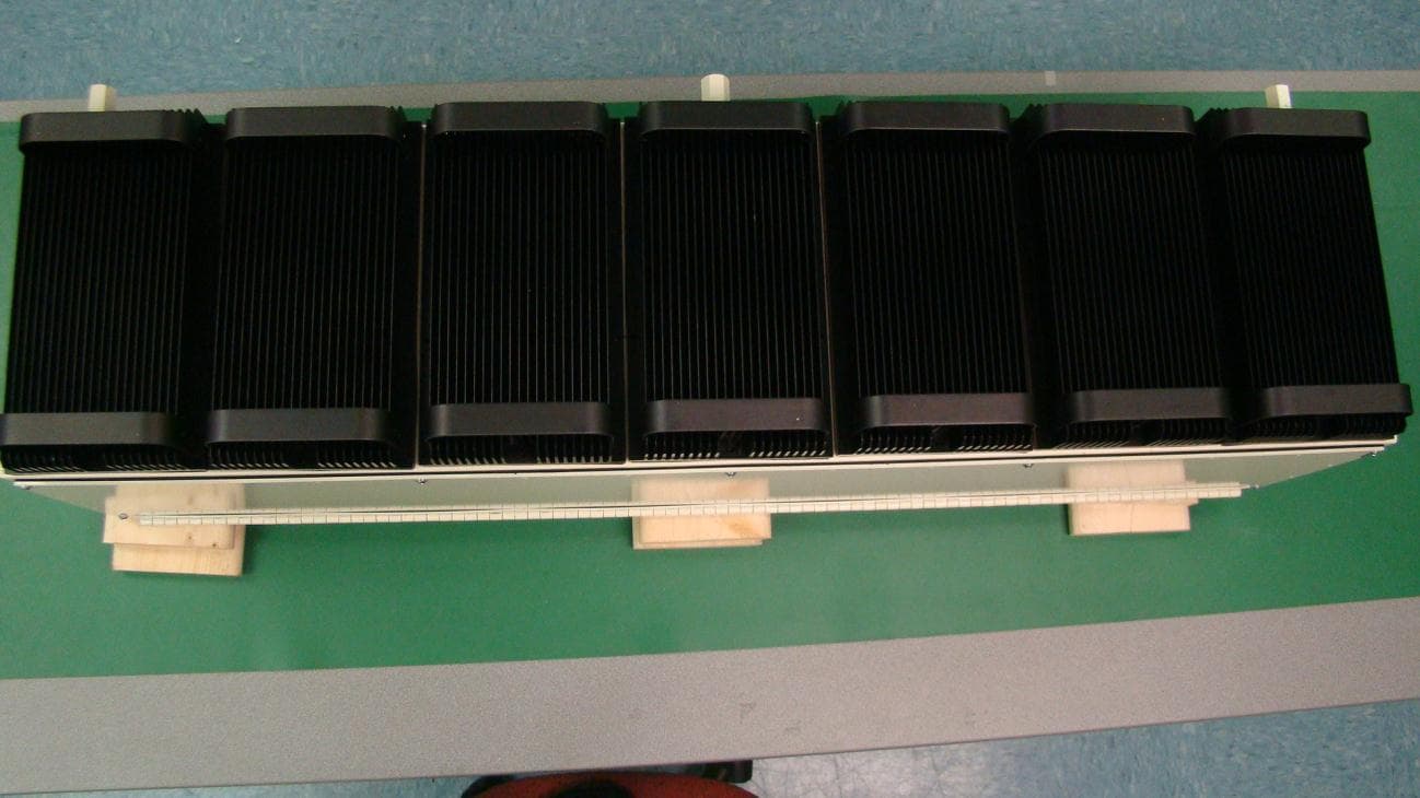
Q4VFS42R-AWS-5
Apr 03, 2011Repeater; Plug-in Service Module, 2.1 GHz AWS Band
Equipment Class
TNB - Licensed Non-Broadcast Station TransmitterQ4VFS45R-CELL-2
Apr 03, 2011Repeater; Plug-in Service Module, 850 MHz Cellular
Equipment Class
TNB - Licensed Non-Broadcast Station Transmitter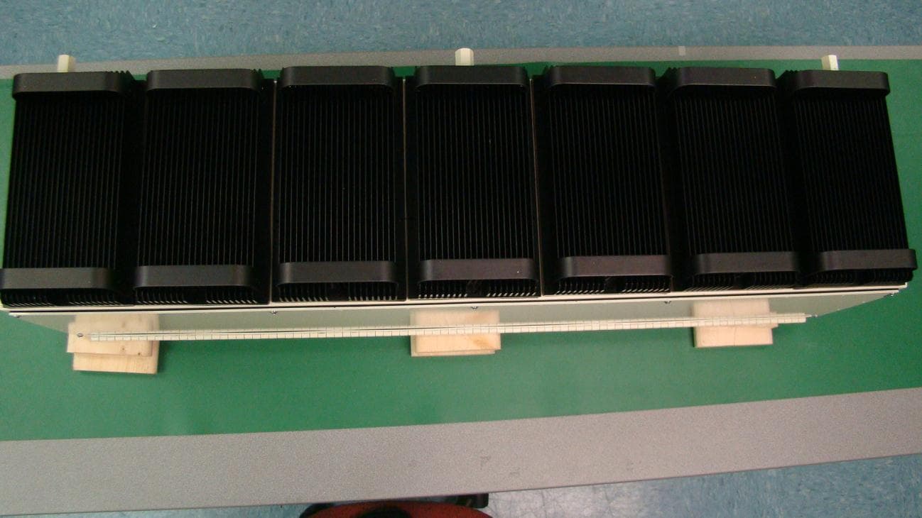
Q4VFS42R-IDEN-2
Apr 03, 2011Repeater; Plug-in Service Module, 800/900 MHz iDen
Equipment Class
TNB - Licensed Non-Broadcast Station Transmitter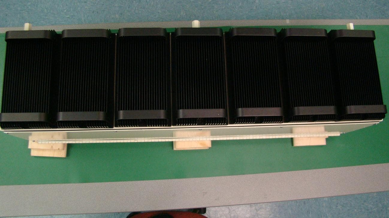
Q4VFS42R-PCS-5
Apr 03, 2011Repeater; Plug-in Service Module, 1.9 GHz PCS Band
Equipment Class
PCB - PCS Licensed Transmitter