Q4VFS71C-85Digital Narrowband Class A Signal Booster
Fiber-Span LLC
Click to zoom
Application Details
- Equipment Class
- B2I - Part 20 Industrial Booster (CMRS)
- Date of Grant
- Nov 04, 2015
- Application Purpose
- Original Equipment
- Date of Application
- Oct 25, 2015
- Equipment Note
- Digital Narrowband Class A Signal Booster
- Frequency Range
- 862.00000000 - 869.00000000
- Company
- Fiber-Span LLC
- Country
- United States
Documents & Files
Document Text
Text extracted from the exhibit documents filed with the FCC. Open a document above to read the original.
Users Manual
FS71C-85 Series User Manual| I $Pyright © 2015 Fiber-Span FS71C-85-USR U se r Op era t io n & M a in te na n ce Ma n ua l 800 MHz Digital Narrowband Repeater Unit Fiber-Span, 3434 Route 22 West - Branchburg, NJ 08876 - 908•253•9080, fax 908•273•9086 - www.fiber-span.com FS71C-85 Series User Manual| II Copyright © 2015 Fiber-Span Copyright © 2014 Fiber-Span. All Rights Reserved. No part of this publication, or any software included with it may be reproduced, stored in a retrieval system, or transmitted in any form or by any means, including photocopying, electronic, mechanical, recording or otherwise, without the prior written permission of the copyright holder. Fiber-Span provides this document as is, without any warranty of any kind either expressed or implied including, but not limited to, the implied warranties of merchantability and fi tness of a particular purpose. Fiber-Span may make changes or improvements in the equipment, software, or specifi cations described in this document at any time and without notice. These changes will be incorporated in new releases of this document. This document may contain technical inaccuracies or typographical errors. Fiber-Span waives responsibility for any labor, materials, or costs incurred by any person or party as a result of using this document. Fiber-Span and any of its affi liates shall not be liable for any damages (including, but not limited to, consequential, indirect or incidental, special damages or loss of profi ts or date) even if they were foreseeable and Fiber-Span has been informed of their potential occurrence, arising out of or in connection with this document or its use. Fiber-Span 3434 Route 22 W., Suite 140 Branchburg, New Jersey 08876 Tel: (908) 253-9080 Fax: (908) 253-9086 www.fi ber-span.com Limitation of Liability FS71C-85 Series User Manual| III Copyright © 2015 Fiber-Span Warnings Only a qualifi ed technician shall be allowed to operate the unit after reading and understanding all the guidelines in this manual. An exclamation point denotes attention to state- ment required. Follow and comply with all site Safety Policies. Do not touch heat sink while equipment is in operation, as surface may be very HOT. Terminate every RF port with a 50 Ohm load. Note: Factory limit is set to +37 dBm composite output power for both UL & DL paths. Part 20 & 90 Signal Boosters THIS IS A 90.219 CLASS A DEVICE” “WARNING. This is NOT a CONSUMER device. It is designed for installation by FCC LICENSEES and QUALIFIED INSTALLERS. You MUST have an FCC LICENSE or express consent of an FCC Licensee to operate this device. You MUST register Class B signal boosters (as defi ned in 47 CFR 90.219) online at HYPERLINK “http://www.fcc.gov/signal-boosters/registration” www.fcc.gov/signal-boosters/ registration. Unauthorized use may result in signifi cant forfeiture penalties, including penalties in excess of $100,000 for each continuing violation.” Part 20 Industrial Boosters “WARNING. This is NOT a CONSUMER device. It is designed for installation by FCC LICENSEES and QUALIFIED INSTALLERS. You MUST have an FCC LICENSE or express consent of an FCC Licensee to operate this device. Unauthorized use may result in signifi cant forfeiture penalties, including penal- ties in excess of $100,000 for each continuing violation.” FS71C-85 Series User Manual| IV Copyright © 2015 Fiber-Span Revision History VersionDescriptionDateAuthor 1.0Initial Release01-Aug-2014DT 1.1GUI Screen shots and descriptions updated01-Feb-2015HW 1.1apg18 DL Setup25-Feb-2015HW 1.1kFCC statement clarifi ed10-Aug-2015HW Information in this document is subject to change without notice. Please send comments to: E-mail: [email protected] Phone: 908-253-9080 | Fax: 908-253-9086 FS71C-85 Series User Manual| V Copyright © 2015 Fiber-Span Table of Contents Limitation of Liability. . . . . . . . . . . . . . . ii Warnings. . . . . . . . . . . . . . . . . . . . iii Revision History. . . . . . . . . . . . . . . . . iv 1Company Information 1 Contact. . . . . . . . . . . . . . . . . . . . 1 2Product Introduction 2 Theory of Operation . . . . . . . . . . . . . . . 4 Product Applications. . . . . . . . . . . . . . . 5 3Detailed Description 8 Overview. . . . . . . . . . . . . . . . . . . . 8 Amplifiers. . . . . . . . . . . . . . . . . . . . 8 Duplexers. . . . . . . . . . . . . . . . . . . . 9 Alarms. . . . . . . . . . . . . . . . . . . . . 9 GUI Interface. . . . . . . . . . . . . . . . . . . 10 Specifications. . . . . . . . . . . . . . . . . . 11 Outline Drawings. . . . . . . . . . . . . . . . . 12 4Installation Procedure 14 Environment. . . . . . . . . . . . . . . . . . . 14 Connectorization. . . . . . . . . . . . . . . . . 14 Anchoring. . . . . . . . . . . . . . . . . . . . 14 Wall-mount Version. . . . . . . . . . . . . . . 14 Rack-mount Version. . . . . . . . . . . . . . . 14 Alarms. . . . . . . . . . . . . . . . . . . . 14 Grounding. . . . . . . . . . . . . . . . . . . . 15 FS71C-85 Series User Manual| VI Copyright © 2015 Fiber-Span 5Setup Procedure 16 Overview. . . . . . . . . . . . . . . . . . . . 16 Cautionary Notes. . . . . . . . . . . . . . . . . 16 Contents of Package. . . . . . . . . . . . . . . . 16 HRU Control. . . . . . . . . . . . . . . . . . . 16 Downlink Setup. . . . . . . . . . . . . . . . . . 18 De-rating Table. . . . . . . . . . . . . . . . . . 20 HRU Uplink Control. . . . . . . . . . . . . . . . 20 Uplink Gain Setup. . . . . . . . . . . . . . . . . 21 6Troubleshooting 22 HRU Alarms. . . . . . . . . . . . . . . . . . . 22 Power LED Indicator. . . . . . . . . . . . . . . . 23 Amplifier Alarms. . . . . . . . . . . . . . . . . 23 Fan Blockage. . . . . . . . . . . . . . . . . . . 23 Door Lights. . . . . . . . . . . . . . . . . . . 23 7Warranty Information 24 General Warranty. . . . . . . . . . . . . . . . . 24 Limitations of Warranty. . . . . . . . . . . . . . 24 Limitations of Damages. . . . . . . . . . . . . . 24 Return Material Authorization (RMA). . . . . . . . . 24 8FCC Statement 2…
Text truncated - open the document above for the full version.
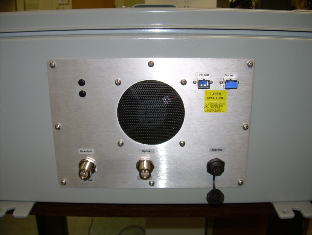
External Photos
Fiber-Span | 3434 Rte. 22W, Suite 140 | Branchburg, NJ 08876 | Tel: 908-253-9080 | Fax: 908-253-9086 www.fiber-span.com Fiber-Span | 3434 Rte. 22W, Suite 140 | Branchburg, NJ 08876 | Tel: 908-253-9080 | Fax: 908-253-9086 www.fiber-span.com
ID Label/Location Info
Fiber-Span | 3434 Rte. 22W, Suite 140 | Branchburg, NJ 08876 | Tel: 908-253-9080 | Fax: 908-253-9086 www.fiber-span.com Fiber Span Label Location Fiber-Span | 3434 Rte. 22W, Suite 140 | Branchburg, NJ 08876 | Tel: 908-253-9080 | Fax: 908-253-9086 www.fiber-span.com THIS IS A 90.219 CLASS A DEVICE WARNING. This is NOT a CONSUMER device. It is designed for installation by FCC LICENSEES and QUALIFIED INSTALLERS. You MUST have an FCC LICENSE or express consent of an FCC Licensee to operate this device. You MUST register Class B signal boosters (as defined in 47 CFR 90.219) online at www.fcc.gov/signal-boosters/registration. Unauthorized use may result in significant forfeiture penalties, including penalties in excess of $100,000 for each continuing violation. Part 20 Industrial Boosters WARNING: This is NOT a CONSUMER device. It is designed for installation by FCC LICENSEES and QUALIFIED INSTALLERS. You MUST have an FCC LICENSE or express consent of an FCC Licensee to operate this device. Unauthorized use may result in significant forfeiture penalties, including penalties in excess of $100,000 for each continuing violation.” Part 20 & 90 Signal Booster Label Location FCC ID: Q4VFS71C-85
Internal Photos
Control Board April, 20 2015 HD29925-SP Assembly 1 DC Distribute Input & Pre Drive & Main Final Base Assembly 2 Loop Module (same body) 1 st Loop (Top) + 2 nd Loop & Output Section (Bottom) Assembly 3 Base + Loop Module Assembly 4 Base + Loop Module + Control Board Control Board (Control / Alarm / Monitor) + Loop Module Assembly 5 Base + Loop Module + Control Board + Delay Line Delay Line Loop Module Front(Connector) View RF Output RF Input Interface DC IN +28V GND NC Top View Fiber-Span | 3434 Rte. 22W, Suite 140 | Branchburg, NJ 08876 | Tel: 908-253-9080 | Fax: 908-253-9086 www.fiber-span.com Fiber-Span | 3434 Rte. 22W, Suite 140 | Branchburg, NJ 08876 | Tel: 908-253-9080 | Fax: 908-253-9086 www.fiber-span.com LNA Board PA Supplement Board
Operational Description
3434 Rt. 22W, Suite 140 | Branchburg, New Jersey 08876 | (908) 253.9080 | www.fi ber-span.com 806 - 869 MHz Digital Narrowband Class A Signal Booster FS71C-85 Key Features : • 806 - 869 MHz Frequency Range • Class A Narrowband for Public Safety applications • +37 dbm Linear Composite Output Power • Up to 16 or 32 (dual) full duplex channels in 4U subrack • 120 dB System Gain per channel max • NFPA 72 Compliant (wall-mount Version) • Individual AGC and Squelch settings per channel • Fiber-Fed DAS Con gurations, with or without Power Ampli ers or Duplexers • Programmable Filter Bandwidths, Selectivity & Group Delay DESCRIPTION Fiber-Span’s FS71C-85 Narrowband Digital Technology integrates uplink and downlink programmable front-end narrowband lters with broadband Multi-Carrier Power Ampli ers (MCPAs), to deliver a Bi-Directional Narrowband Signal Booster. The FS71C-85 uplink ampli ers can be speci ed as truly channelized narrowband lters tuned to transmit only your licensed channels, in compliance with the FCC de nition for Class-A Signal Boosters. It can be con gured with up to 16 or 32 fully programmable lters per path, Uplink and Downlink. The downlink path lters can be broader for reduced delays to accommodate the digital modulation signals timing constraints in the overlap coverage areas. Each lter-window has an input sensitivity of -105 dBm and up to 120 dB of available gain. The FS71C-85 is a patent-pending design for multi-carrier two-way rebroadcast systems, where signi cantly high dynamic range is required on a channel-per-channel basis, while delivering lower and smoother group delay ripple. The individual AGC per channel feature essentially eliminates the uplink near-far concern prevalent in many Public Safety broadband DAS systems. The lter’s bandwidths and selectivity can be speci ed by the user in order to achieve very narrow lter windows to optimize between rejection and latency. The individual receive threshold level (RF Squelch) per lter ensures clean output spectrum with no ampli ed noise if in-active. A variety of pre and post-rebanded internal duplexer options are available for additional interference protection and multi-service/multi- band compatibility over broadband DAS systems. Also available are con guration options that exclude the portable side duplexer and downlink MCPA for direct compatibility with Fiber Optic DAS systems. Consult Fiber-Span Sales team for custom Bi-Directional Ampli er con gurations and ber optic options including WDM. Refer to separate data sheets for VHF & UHF bands. Fiber-Span is a world-leading manufacturer of RF ON FIBER ® Communication Network Products for in-building, in-tunnel and outdoor coverage extension systems serving the Commercial Wireless, Public Safety, Government and Military markets. • Shopping Malls • Warehouses • Parking Garages • Airports • Justice Centers • Manufacturing Facilities • Stadiums • Convention Centers • Universities • Tunnels • Subways Applications : 3434 Rt. 22W, Suite 140 | Branchburg, New Jersey 08876 | (908) 253.9080 www.fi ber-span.com | techinfo@fi ber-span.com Specifications FS71C-85 DescriptionSpeci cations Frequency Range: 806-824 MHz / 851-869 MHz range The overall system bandwidth per path (UL & DL) could be speci ed as 3, 7, 10, 15 or 18 MHz. Note: The bandwidth option chosen will limit operation within that bandwidth only. Narrowband lters Selectivity – Adjacent Channel Rejection (ACR): 20-70 dB, The Filters Response-Type, Group Delay, Bandwidth and Selec- tivity are software-de ned. Absolute Group Delay: 10-120 uSec, Factory set per customer speci cations NOTE: Filter selection determines bandwitdh, rejection / selectivity and latency. A wider bandwidth fi lter will have less rejection of out-of band spurious but also lower latency. A narrower fi lter will have better rejection but higher delay. Operational bandwidth is adjustable and has a maximum of 4 MHz (model DD option 3A & 3B have a maximum of 3 MHz). Channels can be selected within the operational bandwidth, and the system will only function inside this bandwidth. Please consult Sales with your specifi c requirements. System net gain per lter window: 120 dB max. Automatic Gain Control (AGC) range, on a per lter-window basis: 60 dB Constant Output level regardless of input level variations, per lter: ± 2 dB Broadband input power attenuator adjustment range, per path UL/DL: 30 dB Maximum input power (composite) for no-damage, per path UL/DL: -30 dBm System OIP3: > +63 dBm System Output Power - Linear Power : 37 dBm, 5 watts (ALC set for FCC compliance) System Output Power Automatic Level Control (ALC), composite, factory limited for compliance with FCC Signal Boosters maximum power = 5W: variable set-point 32 ~ 37 dBm (5 Watts) (Note: +37dBm is maximum output power) Composite output power level adjustment range: 20 dB Input (Rx) IM Rejection: >60 dB Spurious & harmonics outputs: <= -20 dBm Mechanical & Environmental Rackmount 19 in. shelf. (Optional wallmount enclosure upon request) Up to 16 channels per Uplink and per Downlink: 4U, 18 inches depth Up to 32 channels per Uplink and per Downlink: 4U, 18 inches depth Weight: 4U enclosure: 44 lbs. (20 Kg), Operating ambient temperature range: -30 to +50° Celsius MTBF: > 90,000 hours, > 70,000 hours ( ber-fed versions) Power Requirements, 100-240 Vac 50/60Hz: 175W (dual ampli er version). 100 watts (single ampli er) Identi cation Part Number FS71CFS71C-85XEDDYYZMM Where: X=Downlink PA, (E=37dBm, N=No MCPA) 1 MM=Mounting (RM=Rack-mount, 4X=Nema 4X Wall- mount) YY=Number of channels (1 thru 16, or 32 for dual unit) Number of active channels (1 to 16) is settable by user via GUI Z=Mobile Side Duplexer (N= No Duplexer, D=Duplexer) 2 DD=Duplexer Bandwidth: 3A=3 MHz, 806-809/851-854 MHz 3B=3 MHz, 821-824/866-869 MHz 07=7 MHz, 817-824/862-869 MHz 09=9 MHz, 806-815/851-860 MHz 15=15 MHz, 806-821/851-866 MHz 18=18 MHz, 806-824/851-869 MHz Example: FS71C-85E…
Text truncated - open the document above for the full version.
RF Exposure Info
Prediction of MPE limit at a given distance Equation from page 18 of OET Bulletin 65, Edition 97-01 S = power density P = output power G = antenna gain R = distance DLUL Output Power37(dBm)37(dBm) Output Power5012(mW)5012(mW) Antenna Gain2(dBi)*0(dBi) Antenna Gain1.58(numeric)1.00(numeric) Distance100(cm)100(cm) Duty Cycle:100(%)100(%) Frequency851(MHz)806(MHz) MPE Limit General Public0.567(mW/cm^2)0.537(mW/cm^2) Power Density0.063(mW/cm^2)0.040(mW/cm^2) Margin9.53(dB)11.29(dB) * derived from 4.85 dBd with 5 dB cable loss 2 4R PG S p =
Test Report
935210 D02 v02r01 APPENDIX D—Cross-reference Notes to 935210 D05 v01, 935210 D02 v03, C63.26/D15 # 935210 D02 v02r01 935210 D05 v01, 935210 D02 v03 C63.26/D15 Test Firm Comments 01 BOOSTER, AMPLIFIER, AND REPEATER INTERIM BASIC AUTHORIZATION PROCEDURES D.1 GENERAL The interim guidance in this appendix is intended to support uniform basic procedures for equipment authorizations of amplifier, booster, and repeater devices, other than part 20 Consumer Boosters. This includes typical in-building radiation systems consisting at a minimum of one host unit and one or more remote units, used to improve service reliability inside buildings or other structures located within particular licensed service areas. Manufacturers or test labs should obtain prior FCC review and approval for test procedures used for industrial signal boosters that deviate significantly from those herein. For Consumer Signal Boosters, uniform test procedures consistent with the requirements in the Order are continuing under review and development in the ANSI ASC C63® working group (i.e., see KDB Publication 935210 D03 and KDB Publication 935210 D04). In addition, per the Order for example §§ 90.219(d) and 90.219(e) contain specific provisions for which information and test data must be included in applications; 1 uniform test procedures for the § 90.219 requirements will be amended to KDB Publication 935210 as soon available. general 02 D.2 BASIC TERMS AND DEFINITIONS The following general definitions are applicable for the purposes of this appendix. External radio frequency power amplifier (ERFPA) - any device which, (1) when used in conjunction with a radio transmitter signal source, is capable of amplification of that signal, and (2) is not an integral part of a radio transmitter as manufactured. The EAS equipment class AMP is used only for an ERFPA device inserted between a transmitter (TNB/PCB) and an antenna (has only one antenna port). The term “extender” is generally the same as booster, but booster should be used rather than extender. Booster is a device that automatically reradiates signals from base transmitters without channel translation, for the purpose of improving the reliability of existing service by increasing the signal strength in dead spots. 2 An “inbuilding radiation system” is a signal booster. These devices are not intended to extend the size of coverage from the originating base station. 3 A booster can be either single or multiple channels. Repeater is a device that retransmits the signals of other stations. Repeaters are different from boosters in that they can include frequency translation and can extend coverage beyond the design of the original base station. A repeater is typically single channel but can also be multiple channels. The term “translator” is generally the same as repeater, but repeater should be used rather than translator. 935210 D02 v03 Appdx A 1 See also §§ 2.911(b), 2.947(a)(3), 2.947(c), 2.947(d), 2.947(e), 2.962(f)(5)(i). 2 § 22.99 Dead spots. Small areas within a service area where the field strength is lower than the minimum level for reliable service. Service within dead spots is presumed. 3 § 90.219(d)(2) Signal boosters must not be used to extend PLMRS stations’ normal operating range. 03 D.3 POLICIES AND PROCEDURES For devices other than consumer signal boosters, tests should be done with each typical signal, e.g., for F3E emissions use 2500 Hz with 2.5 kHz or 5 kHz deviation. Use of CW signal for some tests is acceptable in lieu of actual emission, in cases when CW signal gives worst case results. 935210 D05 v01 3.1), 4.1) C63.26/D15 7.2.2.1, 7.2.3.1 04 D.3) a) Form 731 entries 4 935210 D02 v03 C.2) done 05 D.3) a) 1) For ERFPA as defined above D.3) a) 1) i) In one enclosure D.3) a) 1) i) a) Equipment Class – AMP D.3) a) 1) i) b) List AMP in frequency tolerance field of Form 731 D.3) a) 1) i) c) List emission designators without necessary bandwidth (e.g., F3E, F1D) D.3) a) 1) ii) In two enclosures D.3) a) 1) ii) a) Does not exist (if it does, use same entries as for one enclosure) 935210 D02 v03 C.2) a) 06 D.3) a) 2) For Booster as defined above D.3) a) 2) In one enclosure D.3) a) 2) i) Equipment Class –BOS, B2I, B9A, B9B D.3) a) 2) i) a) List AMP in frequency tolerance field of Form 731 D.3) a) 2) i) b) List emission designators without necessary bandwidth (e.g., F3E, F1D) D.3) a) 2) i) c) List in Form-731 description or comments field the word “booster” D.3) a) 2) ii) In two enclosures (host/remote) D.3) a) 2) ii) a) Two separate FCC IDs/applications D.3) a) 2) ii) b) Equipment Class –BOS, B2I, B9A, B9B D.3) a) 2) ii) c) List AMP in frequency tolerance field of Form 731 D.3) a) 2) ii) d) List emission designators without necessary bandwidth (e.g., F3E, F1D) D.3) a) 2) ii) e) List in comments field the words “Part of booster system used with FCC ID: xxxyyy.” (Where xxxyyy is FCC ID of other device(s) in system). 935210 D02 v03 C.2) b) 07 D.3) a) 3) For Repeater as defined above D.3) a) 3) i) In one enclosure D.3) a) 3) i) a) Equipment Class – BOS, B2I, B9A, B9B D.3) a) 3) i) b) List AMP in frequency tolerance field of Form 731 if device contains no frequency translation; otherwise, measure frequency tolerance and list. D.3) a) 3) i) c) List in comments field the word “repeater” D.3) a) 3) ii) In two enclosures (host/remote) D.3) a) 3) ii) a) Two separate FCC IDs/applications D.3) a) 3) ii) b) Equipment Class – BOS, B2I, B9A, B9B D.3) a) 3) ii) c) List AMP in frequency tolerance field of Form 731 if device contains no frequency translation; otherwise, measure frequency tolerance and list. D.3) a) 3) ii) d) List in comments field the words “Part of repeater system used with FCC ID: xxxyyy.” (Where xxxyyy is FCC ID of other device(s) in system). 935210 D02 v03 C.2) c) 4 Before February 20, 2013, booster and repeater device submissions had used AMP, PCB, or TNB equipment classes; all new grants for nonconsumer booster devices shall use Bxx (BOS, B2I, B9A, or B9B) equipm…
Text truncated - open the document above for the full version.
Test Report
www.nemko.com Nemko Canada Inc., a testing laboratory, is accredited by the Standards Council of Canada. The tests included in this report are within the scope of this accreditation FCC 47 CFR Part 90; Date: April 2015 SCC Accredited LAB LAB Accrédité CCN TM ONE WORLDOURAPPROVAL Test report 279893-1TRFWL Date of issue: September 23, 2015 Applicant: Fiber-Span Product: Digital Narrowband Class A Signal Booster Model: FS71C-85 FCC ID: Q4VFS71C-85 Specification: FCC 47 CFR Part 90 Private land mobile radio services Report reference ID: 279893-1TRFWL Page 2 of 28 Test location Company name Nemko Canada Inc. Address 303 River Road City Ottawa Province Ontario Postal code K1V 1H2 Country Canada Telephone +1 613 737 9680 Facsimile +1 613 737 9691 Toll free +1 800 563 6336 Website www.nemko.com Site number FCC test site registration number: 176392 (3 m semi anechoic chamber) Tested by Kevin Rose, Wireless/EMC Specialist Reviewed by Andrey Adelberg, Senior Wireless/EMC Specialist Date September 23, 2015 Signature Limits of responsibility Note that the results contained in this report relate only to the items tested and were obtained in the period between the date of initial receipt of samples and the date of issue of the report. This test report has been completed in accordance with the requirements of ISO/IEC 17025. All results contain in this report are within Nemko Canada’s ISO/IEC 17025 accreditation. Copyright notification Nemko Canada Inc. authorizes the applicant to reproduce this report provided it is reproduced in its entirety and for use by the company’s employees only. Any use which a third party makes of this report, or any reliance on or decisions to be made based on it, are the responsibility of such third parties. Nemko Canada Inc. accepts no responsibility for damages, if any, suffered by any third party as a result of decisions made or actions based on this report. © Nemko Canada Inc. Report reference ID: 279893-1TRFWL Page 3 of 28 Table of contents Table of contents .......................................................................................................................................................................................................... 3 Section 1. Report summary ................................................................................................................................................................................. 4 1.1 Applicant and manufacturer .................................................................................................................................................................................... 4 1.2 Test specifications .................................................................................................................................................................................................... 4 1.3 Statement of compliance ......................................................................................................................................................................................... 4 1.4 Exclusions ................................................................................................................................................................................................................. 4 1.5 Test report revision history ...................................................................................................................................................................................... 4 Section 2. Summary of test results ....................................................................................................................................................................... 5 2.1 FCC Part 90 test results ............................................................................................................................................................................................ 5 Section 3. Equipment under test (EUT) details ..................................................................................................................................................... 6 3.1 Sample information .................................................................................................................................................................................................. 6 3.2 EUT information ....................................................................................................................................................................................................... 6 3.3 Technical information .............................................................................................................................................................................................. 6 3.4 Product description and theory of operation ........................................................................................................................................................... 6 3.5 EUT exercise details .................................................................................................................................................................................................. 6 3.6 EUT setup diagram ................................................................................................................................................................................................... 7 Section 4. Engineering considerations .................................................................................................................................................................. 8 4.1 Modifications incorporated in the EUT..................................................................................................................................................................... 8 4.2 Technical judgment ..................................................................................................................…
Text truncated - open the document above for the full version.
Test Setup Photos
www.nemko.com Nemko Canada Inc., a testing laboratory, is accredited by the Standards Council of Canada. The tests included in this report are within the scope of this accreditation setup photos.docx; Date: May 2013 SCC Accredited LAB LAB Accrédité CCN TM ONE WORLDOURAPPROVAL Setup photos 279893-3RADWL Date of issue: May 26, 2015 Applicant: Fiber-Span Product: Digital Narrowband Class A Signal Booster Model: FS71C-85 FCC ID: Q4VFS71C-85 Section 1: Setup photos Report reference ID:279893 -3RADWL Page 2 of 2 Section 1. Setup photos 1.1 Radiated Emissions
Contact Information
Applicant
Alfred Boschulte(CEO)
Test Firm
Nemko Canada Inc. (Ottawa)Charles Neal
Technical Specifications
| # | Rule Parts | Frequency Range | Power Output | Emission | Tolerance |
|---|---|---|---|---|---|
| 2 | 90S | 862 MHz - 869 MHz | 5 W | F3E | Amp |
Other Applications from Fiber-Span LLC
Q4VFS31-15C
Jun 04, 2012Booster
Equipment Class
TNB - Licensed Non-Broadcast Station Transmitter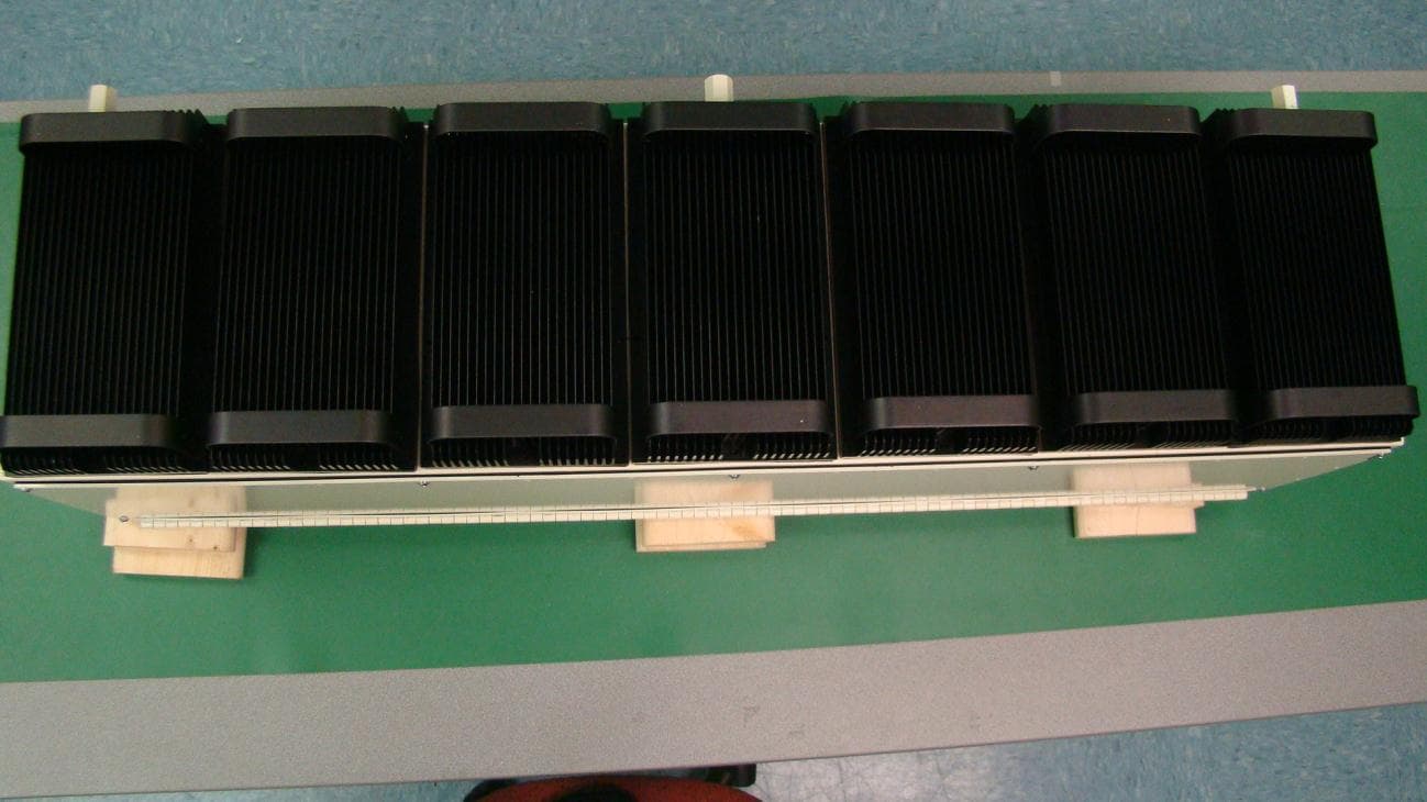
Q4VFS42R-AWS-5
Apr 03, 2011Repeater; Plug-in Service Module, 2.1 GHz AWS Band
Equipment Class
TNB - Licensed Non-Broadcast Station TransmitterQ4VFS45R-CELL-2
Apr 03, 2011Repeater; Plug-in Service Module, 850 MHz Cellular
Equipment Class
TNB - Licensed Non-Broadcast Station Transmitter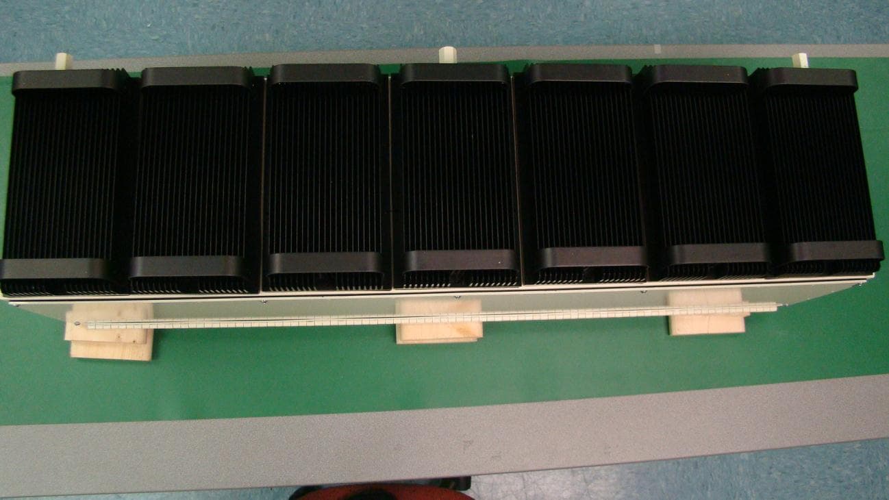
Q4VFS42R-IDEN-2
Apr 03, 2011Repeater; Plug-in Service Module, 800/900 MHz iDen
Equipment Class
TNB - Licensed Non-Broadcast Station Transmitter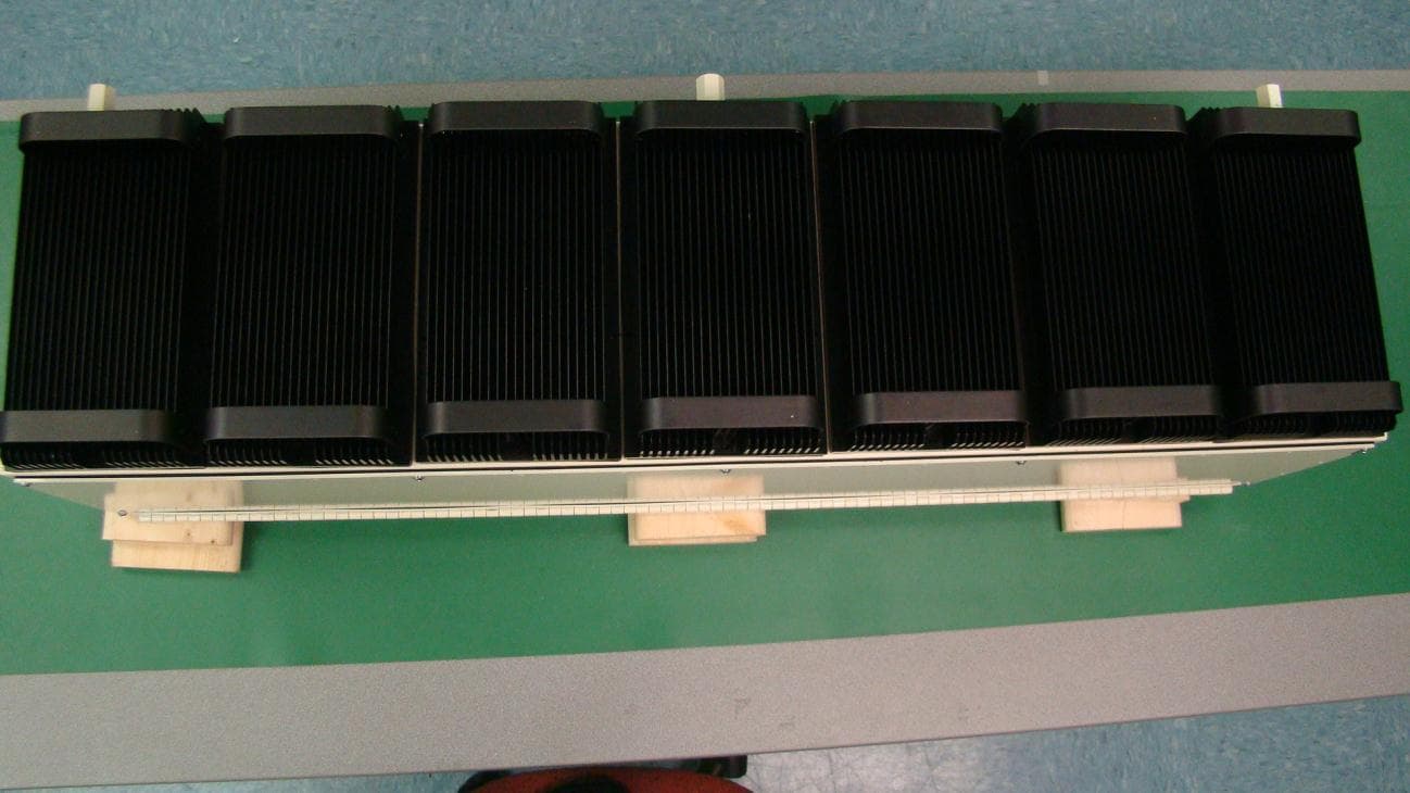
Q4VFS42R-PCS-5
Apr 03, 2011Repeater; Plug-in Service Module, 1.9 GHz PCS Band
Equipment Class
PCB - PCS Licensed Transmitter