Q52TR100802.15.4 2.4GHz Wireless Transceiver
STG Aerospace, Inc,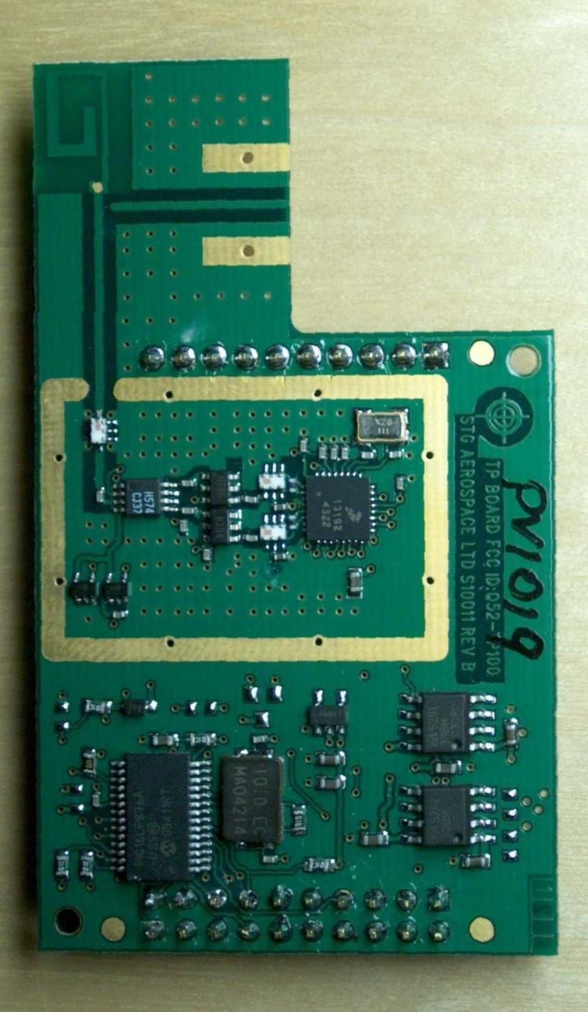
Click to zoom
Application Details
- Equipment Class
- DTS - Digital Transmission System
- Date of Grant
- Apr 23, 2007
- Application Purpose
- Original Equipment
- Date of Application
- Apr 22, 2007
- Equipment Note
- 802.15.4 2.4GHz Wireless Transceiver
- Frequency Range
- 2442.50000000 - 2447.50000000
- Company
- STG Aerospace, Inc,
- Country
- United States
Documents & Files
Document Text
Text extracted from the exhibit documents filed with the FCC. Open a document above to read the original.
Users Manual
Commercial in Confidence S10011 Installation Guide Page 1 of 4 22/1/2007 Commercial in Confidence S10011 Transceiver Module Installation Guide Date: January 22nd 2007 Issue: A1 Summary This guide provides installation instructions for the STG Transceiver Module RS001. LOG OF REVISIONS Rev Date Description Approved A1 22 Jan 2007 Initial Release for S10011 Transceiver FCC Compliance This device complies with Part 15 of the FCC Rules. Operation is subject to the following two conditions: (1) this device may not cause harmful interference, and (2) this device must accept any interference received, including interference that may cause undesired operation. FCC ID Q52-TR100 Caution: Changes or modifications to the S10011 module not expressly approved by STG Aerospace could void the user's authority to operate this equipment. Commercial in Confidence S10011 Installation Guide Page 2 of 4 22/1/2007 Commercial in Confidence CONTENTS 1 INTRODUCTION................................................................................................................. 3 2 FIXING................................................................................................................................... 3 3 POWER CONNECTION...................................................................................................... 3 4 SITING................................................................................................................................... 4 5 LABELLING ......................................................................................................................... 4 Commercial in Confidence S10011 Installation Guide Page 3 of 4 22/1/2007 Commercial in Confidence 1 Introduction The S10011 transceiver is the wireless module part of a remote control system. This installation guide covers the fixing and connecting of the S10011 transceiver module. 2 Fixing The S10011 transceiver is fixed to the host board using connectors JP1 and JP2. No other fixings are used. Electrical connection to the host board is via the connector JP1. JP2 is used to programming the S10011 EEPROM. Figure 1. S10011 connections 3 Power Connection The power supply to the S10011 unit is provided through connector JP1 The connections are as follows: Pin 1 -ve and Pin 12 +5.5 to +9V JP1 JP2 Commercial in Confidence S10011 Installation Guide Page 4 of 4 22/1/2007 Commercial in Confidence 4 Siting The effective radio range of the S10011 transceiver is not more than 100m in an indoor open space, and so for good operation, each unit incorporating a transceiver should be in range of as many other units as possible. The orientation of the unit is not critical, though best range results will be obtained between units when the transceiver boards are in the same plane. 5 Labelling Every unit containing the S10011 module must contain labeling on the outside of the unit stating “Contains FCC ID Q52-TR100” In type no smaller than 8 point.
Block Diagram
Commercial in Confidence S10011 Transceiver Block Diagram Page 1 of 1 22/1/2007 Commercial in Confidence S10011 Transceiver Block Diagram Date: January 22nd 2007 uP regulators regulated supply 10 MHz crystal Modem Tx Rx 16 MHz crystal PA LNA IEEE 802.15.4 TRANCEIVER connector SPI screening can Figure 1. S10011 Block Diagram
Cover Letter(s)
STG Aerospace, Inc. 6043 N.W. 167 th Street, Suite A-14, Miami, Florida 33015 Toll Free 1-888-GLO-4USA / T (305) 828-9811 / F (305) 828-2939 E: [email protected] W: www.stgaerospace.com 12 th February 2007 BABT TCB Balfour House, Churchfield Road, Walton-on-Thames, Surrey, KT12 2TD, To whom it may concern:: This is to certify that STG Aerospace Inc. hereby authorize ASH Communications Ltd, of 5 Shaftesbury Avenue, Southampton, UK to act as our agent in all matters relating to applications for equipment authorization, including the signing of all documents relating to these matters. This authorization expires on 30 th December 2007. We certify that we are not subject to a denial of Federal benefits, that include FCC benefits, pursuant to Section 5301 of the Anti-Drug Abuse Act of 1988, 21 U.S.C. § 862 because of a conviction for possession or distribution of a controlled substance. See 47 CFR 1.2002(b) for the definition of a "party" for these purposes. Sincerely, Gary I. Girard President c.c. Dr Sean O’Kell, STG Aerospace Ltd.
Cover Letter(s)
STG Aerospace, Inc. 6043 N.W. 167 th Street, Suite A-14, Miami, Florida 33015 Toll Free 1-888-GLO-4USA / T (305) 828-9811 / F (305) 828-2939 E: [email protected] W: www.stgaerospace.com 14 th February 2007 BABT TCB Balfour House, Churchfield Road, Walton-on-Thames, Surrey, KT12 2TD, Confidentiality Request for module S10011 Pursuant to Sections 0.457(d)(1)(ii) and 0.459 of the Commission’s Rules, STG Aerospace Inc. hereby requests permanent confidential treatment of information accompanying this application as outlined below: 1. Test report files as provided by TUV Ltd, exhibit 6 2. Schematics and BOM, exhibit 5 3. Description and block diagram, exhibits 4 and 12 The above materials contain trade secrets and proprietary information not customarily released to the public. The public disclosure of these matters might be harmful to the Applicant and provide unjustified benefits to its competitors. The Applicant understands that pursuant to Rule 0.457(d)(1)(ii), disclosure of this Application and all accompanying materials will not be made before the date of the Grant for this Application. Yours sincerely, Gary I. Girard President
Cover Letter(s)
Commercial in Confidence Commercial in Confidence STG Aerospace Inc. S10011 Unlicensed Radio Module Compliance Statement Commercial in Confidence Commercial in Confidence CONTENTS 1 INTRODUCTION.................................................................................................................3 2 UNLICENSED MODULAR TRANSMITTER APPROVAL...........................................3 3 LABEL....................................................................................................................................4 Commercial in Confidence Commercial in Confidence 1 Introduction The S10011 device is a transceiver module used in the control of networked devices. S10011 is known as the “TP Board”. The transceiver module has been designed to meet the general emissions limits of the FCC CFR 47: Parts 15B and C. The frequency used is 2.45 GHz. 2 Unlicensed Modular Transmitter Approval According to DA 00-1047 the requirements for modular transmitter approval are met by the following compliance statements: 1 Own RF Shielding. The transmitter has its own metal shielding, in addition to a ground plane on the bottom of the circuit board. 2. Buffered modulation/data inputs. No data inputs are provided on the board that connect to the transmitter. The processor drives the transmitter directly at a fixed data rate. 3. Supply regulation. The transmitter has power regulation provided on-board by U2, U12 and U13. 4. Transmit antenna. The transmit antenna is permanently attached and is part of the circuit board. 5. Stand-alone test. The emissions tests were carried out in a stand-alone configuration with battery power. The unit is designed for DC operation and will not be used from AC supplies or from units connected to AC supplies. 6. Labeling. The unit will be labeled with its own FCC ID number. Instructions for labeling the outside of the device into which the S10011 is installed are contained in the installation guide. 7. Operating requirements. The S10011 module is designed to operate under the General Limits specified in Section 15.209 and as such there are no specific operational requirements. 8. Exposure requirements. The S10011 module is designed to operate under the General Limits specified in Section 15.209 and as such there are no specific exposure requirements. Commercial in Confidence Commercial in Confidence 3 Label The S10011 module will be labelled (printed directly onto the pcb board) with the FCC ID number Q52-TP100. The module is not visible when installed in system and therefore a label with the FCC ID of the module is located on the out case of the unit carrying the module.
ID Label/Location Info
Label fixed to S10011 host to identify FCC ID of fitted module. BATTERY MODULE PART NUMBER: T10001 SOFTWARE LOAD: BM0406 SERIAL NUMBER: BM00025 CONTAINS FCC ID: Q52-TR100 THIS ARTICLE CONTAINS NON-RECHARGEABLE LITHIUM BATTERIES AND DOES NOT REQUIRE CHARGING OR MAINTAINING CAUTION: IF THIS BATTERY MODULE IS DAMAGED, BATTERIES MUST BE QUARANTINED, INSPECTED AND REPACKED. DO NOT CHARGE, SHORT CIRCUIT OR MUTILATE THE BATTERY, OTHERWISE BATTERY MAY VENT OR RUPTURE RELEASING TOXIC MATERIALS 6043 NW 167 th Street • Suite A-14 • Miami, Florida 33015 BATTERY MODULE PART NUMBER: T10001 SOFTWARE LOAD: BM0406 SERIAL NUMBER: BM00026 CONTAINS FCC ID: Q52-TR100 THIS ARTICLE CONTAINS NON-RECHARGEABLE LITHIUM BATTERIES AND DOES NOT REQUIRE CHARGING OR MAINTAINING CAUTION: IF THIS BATTERY MODULE IS DAMAGED, BATTERIES MUST BE QUARANTINED, INSPECTED AND REPACKED. DO NOT CHARGE, SHORT CIRCUIT OR MUTILATE THE BATTERY, OTHERWISE BATTERY MAY VENT OR RUPTURE RELEASING TOXIC MATERIALS 6043 NW 167 th Street • Suite A-14 • Miami, Florida 33015 BATTERY MODULE PART NUMBER: T10001 SOFTWARE LOAD: BM0406 SERIAL NUMBER: BM00027 CONTAINS FCC ID: Q52-TR100 THIS ARTICLE CONTAINS NON-RECHARGEABLE LITHIUM BATTERIES AND DOES NOT REQUIRE CHARGING OR MAINTAINING CAUTION: IF THIS BATTERY MODULE IS DAMAGED, BATTERIES MUST BE QUARANTINED, INSPECTED AND REPACKED. DO NOT CHARGE, SHORT CIRCUIT OR MUTILATE THE BATTERY, OTHERWISE BATTERY MAY VENT OR RUPTURE RELEASING TOXIC MATERIALS 6043 NW 167 th Street • Suite A-14 • Miami, Florida 33015 BATTERY MODULE PART NUMBER: T10001 SOFTWARE LOAD: BM0406 SERIAL NUMBER: BM00028 CONTAINS FCC ID: Q52-TR100 THIS ARTICLE CONTAINS NON-RECHARGEABLE LITHIUM BATTERIES AND DOES NOT REQUIRE CHARGING OR MAINTAINING CAUTION: IF THIS BATTERY MODULE IS DAMAGED, BATTERIES MUST BE QUARANTINED, INSPECTED AND REPACKED. DO NOT CHARGE, SHORT CIRCUIT OR MUTILATE THE BATTERY, OTHERWISE BATTERY MAY VENT OR RUPTURE RELEASING TOXIC MATERIALS 6043 NW 167 th Street • Suite A-14 • Miami, Florida 33015 EMERGENCY POWER SUPPLY 7 17 18 9 10 11 12 13 14 15 16 1 5 6 22 8 21 23 4 3 GND LPM LPM RN OUTPUT 28V RTN 28V DC TEST LOGIC INPUT LOGIC INPUT BATT -VE CAN+ve CAN-ve EMERGENCY POWER SUPPLY 7 17 18 9 10 11 12 13 14 15 16 1 5 6 22 8 21 23 4 3 GND LPM LPM RN OUTPUT 28V RTN 28V DC TEST LOGIC INPUT LOGIC INPUT BATT -VE CAN+ve CAN-ve EMERGENCY POWER SUPPLY 7 17 18 9 10 11 12 13 14 15 16 1 5 6 22 8 21 23 4 3 GND LPM LPM RN OUTPUT 28V RTN 28V DC TEST LOGIC INPUT LOGIC INPUT BATT -VE CAN+ve CAN-ve EMERGENCY POWER SUPPLY 7 17 18 9 10 11 12 13 14 15 16 1 5 6 22 8 21 23 4 3 GND LPM LPM RN OUTPUT 28V RTN 28V DC TEST LOGIC INPUT LOGIC INPUT BATT -VE CAN+ve CAN-ve
ID Label/Location Info
Commercial in Confidence S10011 FCC marking Page 1 of 1 22/1/2007 Commercial in Confidence S10011 FCC Approvals Marking on module Date: January 22nd 2007 FCC marking in PCB
Test Report
REPORT ON Limited FCC CFR 47: Parts 15 B and C Testing in Support of an Application for Grant of Equipment Authorisation of a STG Aerospace Inc S10011 P Module (2.4GHz transceiver) COMMERCIAL-IN-CONFIDENCE FCC ID: Q52TP100 Report No OR615060/01 Issue 2 March 2006 Competence. Certainty. Quality. ASH Communications Ltd. – Confidential TUV Product Service Ltd, Octagon House, Concorde Way, Segensworth North, Fareham, Hampshire, United Kingdom, PO15 5RL Tel: +44 (0) 1489 558100. Website: www.tuvps.co.uk ; www.babt.com Report Number OR615060/01 Issue 2 Page 1 of 35 COMMERCIAL-IN-CONFIDENCE REPORT ON Limited FCC CFR 47: Parts 15 B and C Testing in Support of an Application for Grant of Equipment Authorisation of a STG Aerospace Inc S10011 P Module (2.4GHz transceiver) FCC ID: Q52TP100 Report No OR615060/01 Issue 2 March 2006 PREPARED FOR ASH Communications Ltd 5 Shaftesbury Avenue Highfield Southampton SO17 1SB PREPARED BY J Plummer Technical Author APPROVED BY J Adams M Jenkins Authorised Signatory Authorised Signatory DATED 22 nd March 2006 This report has been re-issued as Issue 2 to update additional information supplied by the customer. The Test Results are unaffected. ENGINEERING STATEMENT The measurements shown in this report were made in accordance with the procedures described on test pages. All reported testing was carried out on a sample equipment to demonstrate limited compliance with FCC CFR 47: Parts 15 B & C. The sample tested was found to comply with the requirements defined in the applied rules. Test Engineers; J Holcombe A Guy FCC ID: Q52TP100 COMMERCIAL-IN-CONFIDENCE Report Number OR615060/01 Issue 2 Page 2 of 35 COMMERCIAL-IN-CONFIDENCE CONTENTS Section Page No 1 REPORT SUMMARY 1.1 Status.................................................................................................................................. 4 1.2 Introduction ......................................................................................................................... 5 1.3 Product Information............................................................................................................ 6 1.4 Brief Summary of Results................................................................................................... 8 1.5 Test Conditions................................................................................................................... 9 1.6 Deviations from the Standard............................................................................................. 9 1.7 Modification Record............................................................................................................ 9 2 TEST DETAILS Part 15 B 2.1 Spurious Radiated Emissions ............................................................................................ 11 Part 15 C 2.2 Measurement at the Band Edge......................................................................................... 13 2.3 6dB Bandwidth ................................................................................................................... 19 2.4 Maximum Peak Output Power (Radiated).......................................................................... 21 2.5 Spurious Radiated Emissions ............................................................................................ 23 2.6 Peak Power Spectral Density ............................................................................................. 26 3 TEST EQUIPMENT 3.1 Test Equipment .................................................................................................................. 30 3.2 Measurement Uncertainty .................................................................................................. 31 4 PHOTOGRAPHS 4.1 Photographs of Equipment Under Test (EUT)................................................................... 33 5 ACCREDITATION, DISCLAIMERS AND COPYRIGHT 5.1 Accreditation, Disclaimers and Copyright .......................................................................... 35 FCC ID: Q52TP100 COMMERCIAL-IN-CONFIDENCE Report Number OR615060/01 Issue 2 Page 3 of 35 COMMERCIAL-IN-CONFIDENCE SECTION 1 REPORT SUMMARY Limited FCC CFR 47: Parts 15 B and C Testing in Support of an Application for Grant of Equipment Authorisation of a STG Aerospace Inc S10011 P Module (2.4GHz transceiver) FCC ID: Q52TP100 COMMERCIAL-IN-CONFIDENCE Report Number OR615060/01 Issue 2 Page 4 of 35 COMMERCIAL-IN-CONFIDENCE 1.1 STATUS Equipment Under Test S10011 P Module, (2.4GHz transceivers) Objective To undertake measurements to determine the Equipment Under Test's (EUT's) compliance with the specification. Name and Address of Client ASH Communications Ltd 5 Shaftesbury Avenue Highfield Southampton SO17 1SB Manufacturers Name and Address STG Aerospace Inc 6043 NW 167th Street Suite A-14 Miami, Florida 33015 Part Number S10011 Serial Number CKE021 Hardware Version Rev B Declared Variants None Test Specification/Issue/Date FCC CFR 47: Part 15, Subparts B and C: 2003 & 2005 Number of Items Tested One Security Classification of EUT Commercial-in-Confidence Incoming Release Declaration of Build Status Date 8 th February 2006 Disposal Held pending disposal Reference Number Not Applicable Date Not Applicable Order Number ASH066 Date 30 th January 2006 Start of Test 8 th February 2006 Finish of Test 10 th February 2006 Related Documents ANSI C63.4: 2001 FCC 03-287: 2003 FCC 04-165: 2004 FCC ID: Q52TP100 COMMERCIAL-IN-CONFIDENCE Report Number OR615060/01 Issue 2 Page 5 of 35 COMMERCIAL-IN-CONFIDENCE 1.2 INTRODUCTION The information contained within this report is intended to show limited verification of compliance of the STG Aerospace Inc S10011 P Module (2.4GHz transceiver) to the requirements of FCC Specification Parts 15 B and C. Testing was carried out in support of an application for Grant of Equipment Authorisation in the name of STG Aerospace Inc. FCC ID: Q52TP100 COMMERCIAL-IN-CONFIDENCE Report Number OR615060/01 Issue 2 …
Text truncated - open the document above for the full version.
Test Setup Photos
FCC ID: Q52TP100 ASH Communications Ltd S10011 P Module ©2006 Not to be reproduced, except in its entirety, Page 1 of 1 without the Permission of TUV Product Service Ltd BABT Reference: OR615060-01 PHOTOGRAPHS OF TEST SET UP Radiated Emissions
Contact Information
Applicant
Gary Girard(President)
Technical Contact
Non-Technical Contact
STG Aerospace LtdSean O'Kell
[email protected]+44176023232
Test Firm
TUV SUD Product ServiceJensen Adams
Technical Specifications
| # | Rule Parts | Frequency Range | Power Output | Tolerance |
|---|---|---|---|---|
| 1 | 15C | 2.44 GHz - 2.45 GHz | 45.70 mW | 10.0000000000 ppm |
Other Applications from STG Aerospace, Inc,

Q52-13EAQ52
Jul 28, 2003Remote Control Transceiver
Equipment Class
DXT - Part 15 Low Power Transceiver, Rx Verified