Q5N-QT256Wireless Microphone, Model QT-256
Quantum5x Systems Inc.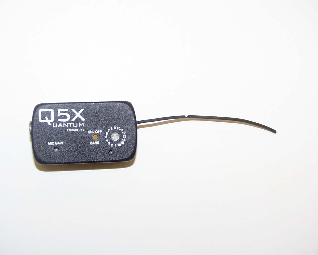
Click to zoom
Application Details
- Equipment Class
- TBT - Licensed Broadcast Transmitter Worn on Body
- Date of Grant
- Aug 05, 2003
- Application Purpose
- Original Equipment
- Date of Application
- Aug 05, 2003
- Equipment Note
- Wireless Microphone, Model QT-256
- Frequency Range
- 690.00000000 - 715.00000000
- Company
- Quantum5x Systems Inc.
- Country
- Canada
Documents & Files
Document Text
Text extracted from the exhibit documents filed with the FCC. Open a document above to read the original.
Users Manual
QUANTUM5X SYSTEMS INC. QT-256 USER GUIDE Quantum5x Systems Inc...............................................1 Controls and connections............................................. 2 Programming frequencies............................................ 4 Technical specifications................................................ 6 Tuning Proceedures..................................................... 7 Certification and conformity.......................................... 8 CONTENTS 2 Quantum5x Systems Inc.Quantum5x Systems Inc. Quantum5x Systems Inc.Quantum5x Systems Inc. Quantum5x Systems Inc. Quantum’s technologies have enhanced the experience and fan enjoyment in ESPN’s and FOX sports coverage of on-air events such as The Great Outdoor Games, The X Games, MLB, NHL games, the All Star Games, and the WNBA. Quantum’s philosophy is to motivate and drive the research and development of products that add value for sports fans, television viewers and movie-goers alike. As the demand for a richer and fuller entertainment experience heightens, Quantum5x delivers a heightened viewing experience across all forms of media. Quantum5x has enhanced some of the world’s most prominent sporting events with new and groundbreaking technologies. “Watch, Listen and Enjoy the Experience of the Future”. 3 4 Controls and connections 1.The 16 - position rotary BANK and CHANNEL switch. 2.The “LED” displays the “BANK” number in GREEN, and the power On/Off in RED. Also charge status: RED indicates charging, GREEN indicates charge complete. 3.The “pushbutton” controls ON/OFF when pressed momen- tarily, turns the transmitter ON or OFF and will set the “Bank” to the Current rotary switch setting. 4.Microphone Gain control turn clockwise to increase mic gain. 5.4 pin mic/charger connector. 6.1/4 wave whip flex antenna. 5 Controls and connections To turn on, momentarily press “pushbutton” (3). The green LED (2) will flash the previously used “BANK” ( 3 flashes = BANK 3). The transmitter is now powered on and the rotary switch (1) will indicate the channel. If the red LED (2) is out the transmitter is in operation. Rotating the channel selector (1) will change the channel. To change the BANK, set the rotary switch (1) To the appropriate BANK number and press the pushbutton (3) until the green LED (2) flashes the new BANK. Then set the rotary switch (1) to the desired cahnnel. To power OFF the transmitter, momentarily press the pushbutton (3). The red LED (2) will light and fade out indicating the transmitter has turned OFF. (It is normal on power up for the transmitter to take from 1-5 seconds to lock on to frequency, this will be indicated by the red LED (2). 6 Programming frequencies C HBA NK 1C HBA NK 3C HBA NK 5C HBA NK 7 1690.0001693.2001696.4001699.600 2690.1002693.3002696.5002699.700 3690.2003693.4003696.6003699.800 4690.3004693.5004696.7004699.900 5690.4005693.6005696.8005700.000 6690.5006693.7006696.9006700.100 7690.6007693.8007697.0007700.200 8690.7008693.9008697.1008700.300 9690.8009694.0009697.2009700.400 10690.90010694.10010697.30010700.500 11691.00011694.20011697.40011700.600 12691.10012694.30012697.50012700.700 13691.20013694.40013697.60013700.800 14691.30014694.50014697.70014700.900 15691.40015694.60015697.80015701.000 16691.50016694.70016697.90016701.100 C HBA NK 2C HBA NK 4C HBA NK 6C HBA NK 8 1691.6001694.8001698.0001701.200 2691.7002694.9002698.1002701.300 3691.8003695.0003698.2003701.400 4691.9004695.1004698.3004701.500 5692.0005695.2005698.4005701.600 6692.1006695.3006698.5006701.700 7692.2007695.4007698.6007701.800 8692.3008695.5008698.7008701.900 9692.4009695.6009698.8009702.000 10692.50010695.70010698.90010702.100 11692.60011695.80011699.00011702.200 12692.70012695.90012699.10012702.300 13692.80013696.00013699.20013702.400 14692.90014696.10014699.30014702.500 15693.00015696.20015699.40015702.600 16693.10016696.30016699.50016702.700 7 Programming frequencies C HBA NK 9C HBA NK 1 1C HBA NK 13C HBA NK 15 1702.8001706.0001709.2001712.400 2702.9002706.1002709.3002712.500 3703.0003706.2003709.4003712.600 4703.1004706.3004709.5004712.700 5703.2005706.4005709.6005712.800 6703.3006706.5006709.7006712.900 7703.4007706.6007709.8007713.000 8703.5008706.7008709.9008713.100 9703.6009706.8009710.0009713.200 10703.70010706.90010710.10010713.300 11703.80011707.00011710.20011713.400 12703.90012707.10012710.30012713.500 13704.00013707.20013710.40013713.600 14704.10014707.30014710.50014713.700 15704.20015707.40015710.60015713.800 16704.30016707.50016710.70016713.900 C HBA NK 10C HBA NK 1 2C HBA NK 14C HBA NK 16 1704.4001707.6001710.8001714.000 2704.5002707.7002710.9002714.100 3704.6003707.8003711.0003714.200 4704.7004707.9004711.1004714.300 5704.8005708.0005711.2005714.400 6704.9006708.1006711.3006714.500 7705.0007708.2007711.4007714.600 8705.1008708.3008711.5008714.700 9705.2009708.4009711.6009714.800 10705.30010708.50010711.70010714.900 11705.40011708.60011711.80011715.000 12705.50012708.70012711.90012650.000 13705.60013708.80013712.00013660.000 14705.70014708.90014712.10014670.000 15705.80015709.00015712.20015750.000 16705.90016709.10016712.30016730.000 8 Technical specifications Dimensions58mm x 34mm x 16.5 mm Power output103 mW Frequency range690 Mhz - 715 Mhz Number of frequencies256 pre-programmed Power Output (EIRP)169 mW Noise reductionProprietory QT companding Adjustable controlsOn/Off/Bank nunber Microphone gain frequency select Specific Absorbance Ratio (SAR)0.68 W/Kg Battery (Renata # ICP633048A-SC)Lithium Ion 3.7 Volt capacity 820mAh Battery Life8 Hrs @ 100 mA AntennaExternal 1/4 wave flex Mic input connector4 pin (FCI) locking MicrophoneCountryman, EMU Lavalier Tuning Proceedures 9 A temperature-compensated 10.000 MHz crystal oscillator provides the frequency reference for the synthesizer. The oscillator frequency is divided down to 25 kHz and remultiplied in the synthesizer to one of the 256 transmit frequencies as selected by the operator via the microcontroller. The output signal is generated by an …
Text truncated - open the document above for the full version.
Cover Letter(s)
May 7 th , 2003 FEDERAL COMMUNICATIONS COMMISSION 7435 Oakland Mills Road Columbia, MD 21046 U.S.A. Subject: Request for withholding from public disclosure the schematic diagrams and system block diagrams pursuant to an application for certification. Applicant: Quantum5x Systems Inc. Product: Wireless Microphone Model: QT-256 FCC ID: Q5N-QT256 Dear Sir/Madam, We, Quantum5x Systems Inc. would like to request that the schematic diagrams and system block diagrams, labeled Exhibit 6, submitted with the application for certification be withheld from public disclosure as per Section 0.459 of FCC Rules. This request is made under the provisions of Section 0.457(d) of the Commission's Rules, and Section 552(b)(4) of the Freedom of Information Act. These sections authorize as a withholding from public inspection materials which would be privileged as a matter of law if retained by the person submitting them, and materials which would not customarily be released to the public by that person. The detailed confidential materials are listed as follows: No. Title Drawing No. Sheet No. 1 Block Diagram Q5X - 1 1 2 Schematic Q5X - 2 1 3 Parts List Q5X - 3 3 4 Technical/Operational description Q5X - 4 2 5 If you have any queries, please do not hesitate to contact us by our numbers: OUR TELEPHONE NO.: (519) 675-6999 Yours truly, Allen Kool President & CEO Quantum5x Systems Inc. 30 Adelaide Street North Ste.12 London, Ontario Canada N6B 3N5 Ph: 519-675-6999 Fax: 519-667-2169 e-mail [email protected]
External Photos
Annex 2 - External Photographs of EUT Photo # 1 Wireless Microphone, Model QT-256 FCC ID: Q5N-QT256 IC: 4614A-QT256 Annex 2 - External Photographs of EUT Photo # 2 Wireless Microphone, Model QT-256 FCC ID: Q5N-QT256 IC: 4614A-QT256
Internal Photos
Annex 3 - External Photographs of EUT Photo # 1 Wireless Microphone, Model QT-256 FCC ID: Q5N-QT256 IC: 4614A-QT256 Annex 3 - External Photographs of EUT Photo # 2 Wireless Microphone, Model QT-256 FCC ID: Q5N-QT256 IC: 4614A-QT256 Annex 3 - External Photographs of EUT Photo # 3 Wireless Microphone, Model QT-256 FCC ID: Q5N-QT256 IC: 4614A-QT256 Annex 3 - External Photographs of EUT Photo # 4 Wireless Microphone, Model QT-256 FCC ID: Q5N-QT256 IC: 4614A-QT256 Annex 3 - External Photographs of EUT Photo # 5 Wireless Microphone, Model QT-256 FCC ID: Q5N-QT256 IC: 4614A-QT256 Annex 3 - External Photographs of EUT Photo # 6 Wireless Microphone, Model QT-256 FCC ID: Q5N-QT256 IC: 4614A-QT256 Annex 3 - External Photographs of EUT Photo # 7 Wireless Microphone, Model QT-256 FCC ID: Q5N-QT256 IC: 4614A-QT256
Parts List/Tune Up Info
Tuning Proceedures 9 A temperature-compensated 10.000 MHz crystal oscillator provides the frequency reference for the synthesizer. The oscillator frequency is divided down to 25 kHz and remultiplied in the synthesizer to one of the 256 transmit frequencies as selected by the operator via the microcontroller. The output signal is generated by an integrated VCO. The reference oscillator is a temperature-compensated, voltage- controlled crystal oscillator. During manufacturing of the transmitter, the potentiometer that sets the control voltage is adjusted so that the reference frequency is 10.0000 MHz. This is accomplished by adjusting a representative transmit frequency to its correct value by means of a frequency counter. Typical frequency tolerance using this method is +/- <0.001%. The VCO and power amplifier operate from precision regulated power supplies. These, and the use of close-tolerance components, fix the output power level. During manufacture the output power level is confirmed with a wattmeter, and adjusted when necessary by changing the value of the resistor which biases the RF power amplifier.
RF Exposure Info
Wireless Microphone Model No.: QT-256 Tested For Quantum5X System Inc. 30 Adelaide Street North, Suite 12 London, Ontario Canada, N6B 3N5 In Accordance With SAR (Specific Absorption Rate) Requirements using guidelines established in IEEE C95.1-1991, FCC OET Bulletin 65 (Supplement C Edition 01-01), Industry Canada RSS-102(Issue 1) and ACA Radiocommunications (Electromagnetic Radiation – Human Exposure) Amendment Standard 2000 (No. 1) UltraTech's File No.: Q5X-001-SAR This Test report is Issued under the Authority of Tri M. Luu, Professional Engineer, Vice President of Engineering UltraTech Group of Labs Date: July 16, 2003 Report Prepared by: JaeWook Choi Tested by: JaeWook Choi Issued Date: July 16, 2003 Test Dates: July 9, 2003 ~ July 10, 2003 The results in this Test Report apply only to the sample(s) tested, which has been randomly selected. UltraTech 3000 Bristol Circle, Oakville, Ontario, Canada, L6H 6G4 Telephone (905) 829-1570 Facsimile (905) 829-8050 Website: www.ultratech-labs.com Email: [email protected] SPECIFIC ABSORPTION RATE (SAR) Page 1 IEEE C95.1-1991, FCC OET Bulletin 65 (Supplement C), Industry Canada RSS-102(Issue 1) and ACA Radiocommunications (Electromagnetic Radiation – Human Exposure) Amendment Standard 2000 (No. 1) Wireless Microphone M/N: QT-256 FCC ID : Q5N-QT256 TABLE OF CONTENTS EXHIBIT 1. INTRODUCTION................................................................................................................................................4 1.1. SCOPE...............................................................................................................................................................................4 1.2. REFERENCES...................................................................................................................................................................4 EXHIBIT 2. PERFORMANCE ASSESSMENT.....................................................................................................................5 2.1. CLIENT AND MANUFACTURER INFORMATION......................................................................................................5 2.2. DEVICE UNDER TEST (D.U.T.) DESCRIPTION..............................................................................................................5 2.3. LIST OF D.U.T.’S ACCESSORIES:.................................................................................................................................. 6 2.4. SPECIAL CHANGES ON THE D.U.T.’S HARDWARE/SOFTWARE FOR TESTING PURPOSES.............................6 2.5. ANCILLARY EQUIPMENT.............................................................................................................................................6 2.6. GENERAL TEST CONFIGURATIONS...........................................................................................................................6 2.6.1. Equipment Configuration...........................................................................................................................................6 2.6.2. Exercising Equipment.................................................................................................................................................6 2.7. SPECIFIC OPERATING CONDITIONS......................................................................................................................................6 2.8. BLOCK DIAGRAM OF TEST SETUP.............................................................................................................................7 EXHIBIT 3. SUMMARY OF TEST RESULTS......................................................................................................................8 3.1. LOCATION OF TESTS.....................................................................................................................................................8 3.2. APPLICABILITY & SUMMARY OF SAR RESULTS.....................................................................................................8 EXHIBIT 4. MEASUREMENTS, EXAMINATIONS & TEST DATA................................................................................9 4.1. TEST SETUP.....................................................................................................................................................................9 4.2. PHOTOGRAPH OF D.U.T....................................................................................................................................................10 4.3. PHOTOGRAPHS OF D.U.T. POSITION........................................................................................................................12 4.3.1. Body Configuration..................................................................................................................................................12 4.3.1.1. Body-worn configuration.........................................................................................................................................................12 4.4. MAXIMUM PEAK SPATIAL-AVERAGE SAR........................................................................................................................13 4.4.1. Maximum Peak Spatial-average SAR Data..............................................................................................................13 4.4.2. Maximum Peak Spatial-Average SAR Location.......................................................................................................13 4.5. SAR MEASUREMENT DATA..............................................................................................................................................14 4.5.1. Body Configuration Result.......................................................................................................................................14 4.5.1.1. Body-worn configuration....................................................................................…
Text truncated - open the document above for the full version.
RF Exposure Info
July 17, 2003 File No.: Q5X-001-SAR Quantum5X System Inc. 30 Adelaide Street North, Suite 12 London, Ontario Canada, N6B 3N5 NOT TRANSFERABLE This Verification Certificate is hereby issued to the named GRANTEE and is VALID ONLY for the equipment identified hereon for use under the rules and regulations listed below: GRANTEE'S NAME: Quantum5X System Inc. PRODUCT UNDER TEST: Wireless Microphone MODEL NO.: QT-256 FCC ID: Q5N-QT256 OPERATING FREQUENCY RANGE: 690 ~ 715 MHz MAX MEASURED RF OUTPUT POWER: 0.103 W conducted DEVICE CATEGORY: Portable EXPOSURE CATEGORY: General Population/Uncontrolled MAX PEAK SPATIAL-AVERAGE SAR 1g : 0.68 W/Kg This wireless portable device has been shown to be compliant for Specific Absorption Rate (SAR) for general population / uncontrolled exposure limit. APPLICABLE STANDARDS: SAR (Specific Absorption Rate) requirements using guidelines established in IEEE C95.1-1991, FCC OET Bulletin 65 (Supplement C Edition 01-01), Industry Canada RSS-102(Issue 1) and ACA Radiocommunications (Electromagnetic Radiation – Human Exposure) Amendment Standard 2000 (No. 1) Approved by: Tri M. Luu, P.Eng. V.P. – Engineering UltraTech 3000 Bristol Circle, Oakville, Ontario, Canada, L6H 6G4 Tel.: (905) 829-1570 Fax.: (905) 829-8050 Website: www.ultratech-labs.com Email: [email protected], Email: [email protected] 2 31040/SIT C-1376 46390-2049 200093-0 00-034
RF Exposure Info
UltraTech Group of Labs July 17, 2003 Quantum5X System Inc. 30 Adelaide Street North, Suite 12 London, Ontario CANADA, N6B 3N5 Attn.: Mr. Allan Kool Subject: Verification Testing in accordance with SAR (Specific Absorption Rate) requirements using guidelines established in: IEEE C95.1-1991, FCC OET Bulletin 65 (Supplement C) Industry Canada RSS-102 (Issue 1) ACA Radiocommunications (Electromagnetic Radiation – Human Exposure) Amendment Standard 2000 (No. 1) Product: Wireless Microphone Model: QT-256 Dear Mr. Kool, The product sample has been tested in accordance with SAR (Specific Absorption Rate) requirements using guidelines established in IEEE C95.1-1991, FCC OET Bulletin 65 (Supplement C), Industry Canada RSS-102 (Issue 1)and ACA Radiocommunications (Electromagnetic Radiation – Human Exposure) Amendment Standard 2000 (No. 1), and the results and observation were recorded in the engineering report, Our File No.: Q5X-001-SAR Enclosed you will find a copy of the engineering report. If you have any queries, please do not hesitate to contact us. Yours truly, Tri Minh Luu, P.Eng Vice President - Engineering Encl. 31040/SIT A96/TH/0093 46390-2049 200093-0 2 00-034 3000 Bristol Circle, Oakville, Ontario, Canada L6H 6G4 Telephone (905) 829-1570 Facsimile (905) 829-8050 Website: www.ultratech-labs.com Email: [email protected]
Test Report
July 11, 2003 TIMCO ENGINEERING INC. P.O. Box 370 849 N.W. State Road 45 Newberry, Florida Subject: Type Acceptance Application under FCC CFR 47, Parts 2 and 74 (Subpart H) - Low Power Auxiliary Stations Operating in the frequency bands 690-715 MHz. Applicant: Quantum5X Systems Inc. Product: Wireless Microphone Model: QT-256 FCC ID: Q5N-QT256 Dear Sir/Madam, As appointed agent for Quantum5X Systems Inc., we would like to submit the application for certification of the above product. Please review all necessary files uploaded to TIMCO Upload Web Site. If you have any queries, please do not hesitate to contact us by our TOLL FREE number: OUR TELEPHONE NO.: 1-877-765-4173 Yours truly, Tri Minh Luu, P. Eng., V.P., Engineering TML/DH Encl. UltraTech Group of Labs 3000 Bristol Circle, Oakville, Ontario, Canada L6H 6G4 Tel.: (905) 829-1570 Fax.: (905) 829-8050 Website: www.ultratech-labs.com Email: [email protected] 31040/SIT C-1376 46390-2049 200093-0 2 00-034 SL2-IN-E-1119R July 11, 2003 Quantum5X Systems Inc. 30 Adelaide Street North, Suite 12 London, Ontario Canada, N6B 3N5 Attn.: Mr. Allen Kool Subject: Certification Testing in accordance with FCC CFR 47, Parts 2 and 74 (Subpart H) - Low Power Auxiliary Stations Operating in the frequency bands 690-715 MHz. Product: Wireless Microphone Model: QT-256 FCC ID: Q5N-QT256 Dear Mr. Kool, The product sample has been tested in accordance with FCC CFR 47, Parts 2 and 74 (Subpart H) - Low Power Auxiliary Stations Operating in the frequency bands 690- 715 MHz, and the results and observation were recorded in the engineering report, Our File No.: Q5X-001FCC74 Enclosed you will find copy of the engineering report. If you have any queries, please do not hesitate to contact us. Yours truly, Tri Minh Luu, P.Eng Vice President - Engineering Encl. UltraTech Group of Labs 3000 Bristol Circle, Oakville, Ontario, Canada L6H 6G4 Tel.: (905) 829-1570 Fax.: (905) 829-8050 Website: www.ultratech-labs.com Email: [email protected] 31040/SIT C-1376 46390-2049 200093-0 2 00-034 SL2-IN-E-1119R Wireless Microphone Model No.: QT-256 FCC ID: Q5N-QT256 Applicant: Quantum5X Systems Inc. 30 Adelaide Street North, Suite 12 London, Ontario Canada, N6B 3N5 Tested in Accordance With Federal Communications Commission (FCC) CFR 47, PARTS 2 and 74 (Subpart H) UltraTech's File No.: Q5X-001FCC74 This Test report is Issued under the Authority of Tri M. Luu, Professional Engineer, Vice President of Engineering UltraTech Group of Labs Date: July 11, 2003 Report Prepared by: Tri Luu, P.Eng. Tested by: Hung Trinh Issued Date: July 11, 2003 Test Dates: July 06-July 10, 2003 The results in this Test Report apply only to the sample(s) tested, and the sample tested is randomly selected. This report must not be used by the client to claim product endorsement by NVLAP or any agency of the US Government. UltraTech 3000 Bristol Circle, Oakville, Ontario, Canada, L6H 6G4 Tel.: (905) 829-1570 Fax.: (905) 829-8050 Website: www.ultratech-labs.com Email: [email protected], Email: [email protected] 2 31040/SIT C-1376 46390-2049 200093-0 SL2-IN-E-1119R 00-034 FCC PARTS 2 and 74, SUBPART H, LOW POWER AUXILIARY STATIONS Contents i Wireless Microphone, Model QT-256 FCC ID: Q5N-QT256 ULTRATECH GROUP OF LABS File #: Q5X-001FCC74 3000 Bristol Circle, Oakville, Ontario, Canada L6H 6G4 July 11, 2003 Tel. #: 905-829-1570, Fax. #: 905-829-8050, Email: [email protected] , Website: http://www.ultratech-labs.com All test results contained in this engineering test report are traceable to National Institute of Standards and Technology (NIST) TABLE OF CONTENTS EXHIBIT 1. SUBMITTAL CHECK LIST...................................................................................................................... 1 EXHIBIT 2. INTRODUCTION ....................................................................................................................................... 2 2.1. SCOPE....................................................................................................................................................................... 2 2.2. RELATED SUBMITAL(S)/GRANT(S) ...............................................................................................................................2 2.3. NORMATIVE REFERENCES ................................................................................................................................. 2 EXHIBIT 3. PERFORMANCE ASSESSMENT ............................................................................................................ 3 3.1. CLIENT INFORMATION ........................................................................................................................................... 3 3.2. EQUIPMENT UNDER TEST (EUT) INFORMATION.................................................................................................... 3 3.3. EUT’S TECHNICAL SPECIFICATIONS................................................................................................................ 4 3.4. LIST OF EUT’S PORTS................................................................................................................................................ 4 3.5. ANCILLARY EQUIPMENT............................................................................................................................................. 4 EXHIBIT 4. EUT OPERATING CONDITIONS AND CONFIGURATIONS DURING TESTS ............................. 5 4.1. CLIMATE TEST CONDITIONS........................................................................................................................................ 5 4.2. OPERATIONAL TEST CONDITIONS & ARRANGEMENT FOR TEST SIGNALS..................................................................... 5 EXHIBIT 5. SUMMARY OF TEST RESULTS ............................................................................................................. 6 5.1. LOCATION OF TESTS .........................................…
Text truncated - open the document above for the full version.
Test Setup Photos
Annex 1 - Photographs of Test Setup Photo # 1 Wireless Microphone, Model QT-256 FCC ID: Q5N-QT256 IC: 4614A-QT256 AC Powerline Conducted Emissions Annex 1 - Photographs of Test Setup Photo # 2 Wireless Microphone, Model QT-256 FCC ID: Q5N-QT256 IC: 4614A-QT256 Radiated Emissions at 3 Meters – Orthogonal Position #1 Annex 1 - Photographs of Test Setup Photo # 3 Wireless Microphone, Model QT-256 FCC ID: Q5N-QT256 IC: 4614A-QT256 Radiated Emissions at 3 Meters – Orthogonal Position #2 Annex 1 - Photographs of Test Setup Photo # 4 Wireless Microphone, Model QT-256 FCC ID: Q5N-QT256 IC: 4614A-QT256 Radiated Emissions at 3 Meters – Orthogonal Position #3
Contact Information
Applicant
Paul Johnson(CEO)
Test Firm
UltraTech Engineering Labs Inc.Tri Luu
Technical Specifications
| # | Rule Parts | Frequency Range | Power Output | Emission | Tolerance |
|---|---|---|---|---|---|
| 1 | 74.861 | 690 MHz - 715 MHz | 103.00 mW | 128KF3E | 0.0010000000 % |
Other Applications from Quantum5x Systems Inc.
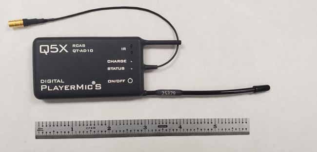
Q5N-QTAD10A15
Mar 16, 2021QT-AD10A15 TRANSMITTER
Equipment Class
DWM - Part 15 Wireless Microphone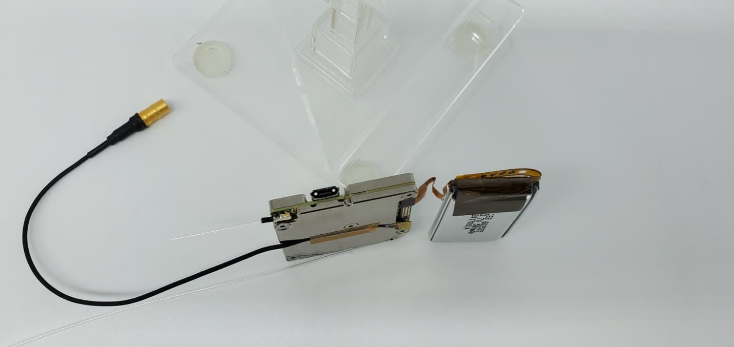
Q5N-QTAD10A
Jul 13, 2020QT-AD10 Module
Equipment Class
TLD - Licensed LPAS Device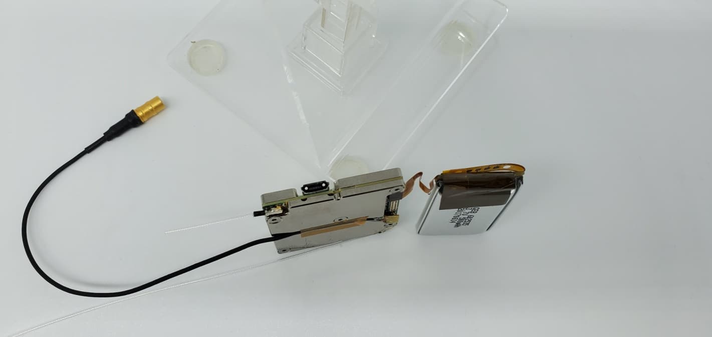
Q5N-QTAD10C
Jun 09, 2020QT-AD10 Module
Equipment Class
TLD - Licensed LPAS Device