Q5N-QTAD10CQT-AD10 Module
Quantum5x Systems Inc.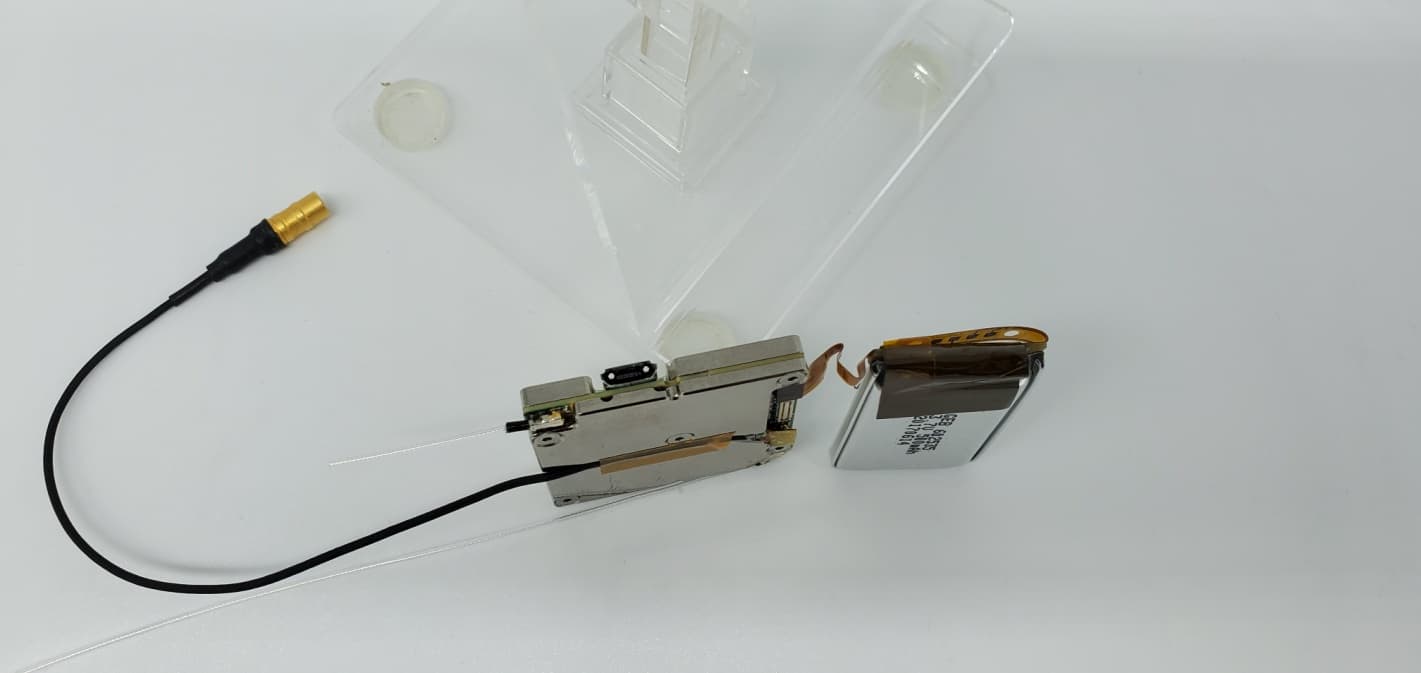
Click to zoom
Application Details
- Equipment Class
- TLD - Licensed LPAS Device
- Date of Grant
- Jun 09, 2020
- Application Purpose
- Original Equipment
- Date of Application
- Jun 03, 2020
- Equipment Note
- QT-AD10 Module
- Frequency Range
- 956.45000000 - 959.72500000
- Company
- Quantum5x Systems Inc.
- Country
- Canada
Documents & Files
Document Text
Text extracted from the exhibit documents filed with the FCC. Open a document above to read the original.
Users Manual
QT‐AD10 Module Description This document describes the use of the QT‐AD10A/C transmitter. History Rev 1 Original QT‐AD10 Module 2 QT‐AD10 TRANSMITTER MODULE Contents Qt‐AD10 Transmitter Module ................................................................................................................... 1 FCC Notices: .................................................................................................................................. 3 AD10 Transmitter Module ........................................................................................................................ 6 Introduction .............................................................................................................................................. 6 Features ................................................................................................................................................ 7 Performance ...................................................................................................................................... 7 Design ................................................................................................................................................ 7 Working with the AD10 Module ............................................................................................................... 7 Out‐of‐the‐Box Setup ............................................................................................................................ 7 Storage Mode ........................................................................................................................................ 7 Standby Mode ....................................................................................................................................... 8 Run Mode .............................................................................................................................................. 8 Control and Configuration of Modules ............................................................................................. 8 Adjusting Module Parameters .......................................................................................................... 8 Specifications .......................................................................................................................................... 11 Input Connector Diagrams .................................................................................................................. 11 Frequency Bands and Transmitter RF Power ...................................................................................... 12 LICENSING INFORMATION ...................................................................................................................... 12 Certifications ........................................................................................................................................... 12 QT‐AD10 Module 3 FCC Notices: Information to users: This device complies with Part 15 of the FCC Rules. Operation is subject to the following two conditions: (1.) This device may not cause harmful interference, and (2.) This device must accept any interference received, including interference that may cause undesired operation. NOTE: This equipment has been tested and found to comply with the limits for a Class B digital device, pursuant to part 15 of the FCC Rules. These limits are designed to provide reasonable protection against harmful interference in a residential installation. This equipment generates, uses and can radiate radio frequency energy and, if not installed and used in accordance with the instructions, may cause harmful interference to radio communications. However, there is no guarantee that interference will not occur in a particular installation. If this equipment does cause harmful interference to radio or television reception, which can be determined by turning the equipment off and on, the user is encouraged to try to correct the interference by one or more of the following measures: — Reorient or relocate the receiving antenna. — Increase the separation between the equipment and receiver. — Connect the equipment into an outlet on a circuit different from that to which the receiver is connected. — Consult the dealer or an experienced radio/TV technician for help. Warning: Wireless microphone users shall rely on the white space databases in part 15, Subpart H to determine that their intended operating frequencies are available for unlicensed wireless microphone operation at the location where they will be used. Wireless microphone users must register with and check a white space database to determine available channels prior to beginning operation at a given location. A user must re‐check the database for available channels if it moves to another location. Warning : Changes or modifications not expressly approved by Quantum5X Systems Inc, could void the user’s authority to operate the equipment. Warning : This module has been designed to operate with only the supplied integrated antenna or the supplied SSMA antenna for the 802.15.4 Radio. Replacing or modifying these antennas is strictly prohibited. QT‐AD10 Module 4 Innovation, Science and Economic Development Canada (ISED) This device contains licence‐exempt transmitter(s)/receiver(s) that comply with Innovation, Science and Economic Development Canada’s licence‐exempt RSS(s). Operation is subject to the following two conditions: 1. This device may not cause interference. 2. This device must accept any interference, including interference that may cause undesired operation of the device. L’émetteur/récepteur exempt de licence contenu dans le présent appareil est conforme aux CNR d’Innovation, Sciences et Développement économique Canada applicables aux appareils radio exempts de licence. L’exploitation est autorisée aux deux conditions suivantes : 1. L’appareil ne doit pas produire de brouillage; 2. L…
Text truncated - open the document above for the full version.
Attestation Statements
Quantum5X Systems Inc. 30 Adelaide Street North London, Ontario, Canada P:519-675-6999, F: 519-667-2162 Federal Communications Commission Authorization and Evaluation Division 1435 Oakland Mills Road Columbia, MD 21046 Date: 03/03/2020 SUBJECT: FCC Application for FCC ID: Q5N, QTAD10C To Whom It May Concern: We, the undersigned, hereby attest to the fact that we will apply the Supplier's Declaration of Conformity (SDoC) procedure pursuant to Part 15, Subpart B - Unintentional Radiators, portion of this composite filing. Regards, Paul Johnson
Attestation Statements
Quantum5X Systems Inc. 30 Adelaide Street North London, Ontario, Canada P:519-675-6999, F: 519-667-2162 Modular Approval Request Applicant: Quantum5X Systems FCC ID: Q5N-QTAD10C 03/03/2020 To Whom It May Concern: Pursuant to Section 15.212(a)(1) of the FCC rules, the Applicant, request for single modular approval, compliance with the requirements are addressed below. Single Modular Approval Requirements Justification (i) The radio elements of the modular transmitter must have their own shielding. The physical crystal and tuning capacitors may be located external to the shielded radio elements. The Module is self contained including top and bottom shield cans that cover all RF and Audio circuitry. (Not including connectors) (ii) The modular transmitter must have buffered modulation/data inputs (if such inputs are provided) to ensure that the module will comply with part 15 requirements under conditions of excessive data rates or over-modulation. The Module’s inputs are buffered and controlled to insure the proper operation. (iii) The modular transmitter must have its own power supply regulation. The Module has it’s own power supply (iv) The modular transmitter must comply with the antenna and transmission system requirements of §§ 15.203, 15.204(b) and 15.204(c). The antenna must either be permanently attached or employ a ‘‘unique’’ antenna coupler (at all connections between the module and the antenna, including the cable). The ‘‘professional installation’’ provision of § 15.203 is not applicable to modules but can apply to limited modular approvals under paragraph (b) of this section. The Module has a hardwired antenna or uses a SSMA connector, which was approved for use by the FCC in the last filing for QT-5100 (v) The modular transmitter must be tested in a stand-alone configuration, i.e., the module must not be inside another device during testing for compliance with part 15 requirements. Unless the transmitter module will be battery powered, it must comply with the AC line conducted requirements found in § 15.207. AC or DC power lines and data input/output lines connected to the module must not contain ferrites, unless they will be marketed with the module (see § 15.27(a)). The length of these lines shall be the length typical of actual use or, if that length is unknown, at least 10 centimeters to The Module is stand-alone and can be tested in this setup. The unit us battery powered insure that there is no coupling between the case of the module and supporting equipment. Any accessories, peripherals, or support equipment connected to the module during testing shall be unmodified and commercially available (see § 15.31(i)). (vi) The modular transmitter must be equipped with either a permanently affixed label or must be capable of electronically displaying its FCC identification number. (A) If using a permanently affixed label, the modular transmitter must be labeled with its own FCC identification number, and, if the FCC identification number is not visible when the module is installed inside another device, then the outside of the device into which the module is installed must also display a label referring to the enclosed module. This exterior label can use wording such as the following: ‘‘Contains Transmitter Module FCC ID: XYZMODEL1’’ or ‘‘Contains FCC ID: XYZMODEL1.’’ Any similar wording that expresses the same meaning may be used. The Grantee may either provide such a label, an example of which must be included in the application for equipment authorization, or, must provide adequate instructions along with the module which explain this requirement. In the latter case, a copy of these instructions must be included in the application for equipment authorization. (B) If the modular transmitter uses an electronic display of the FCC identification number, the information must be readily accessible and visible on the modular transmitter or on the device in which it is installed. If the module is installed inside another device, then the outside of the device into which the module is installed must display a label referring to the enclosed module. This exterior label can use wording such as the following: ‘‘Contains FCC certified transmitter module(s).’’ Any similar wording that expresses the same meaning may be used. The user manual must include instructions on how to access the electronic display. A copy of these instructions must be included in the application for equipment authorization. The module will have all identification permanently applied to the module’s cans. (vii) The modular transmitter must comply with any specific rules or operating requirements that ordinarily apply to a complete transmitter and the manufacturer must provide adequate instructions along with the module to explain any such requirements. A copy of these instructions must be included in the application for equipment authorization. The Module will have a complete datasheet for the configuring and using the module. (viii) The modular transmitter must comply with any applicable RF exposure requirements in its final configuration. The Module will have a max output power of 20 mw which is below the threshold. Sincerely, Paul Johnson
Cover Letter(s)
UltraTech Group of Labs FCC TCB & ISED CB APEC TEL CA0001 1309 CA 0001/2049 AT-1945 SL2-IN-E-1119R Korea KCC-RRA CA0001 3000 Bristol Circle, Oakville, Ontario, Canada L6H 6G4 Tel.: (905) 829-1570 Fax.: (905) 829-8050 Website: www.ultratech-labs.com Email: [email protected] May16, 2020 Ultratech Engineering Labs, Inc. 3000 Bristol Circle Oakville, Ontario L6H 6G4 Subject: Equipment Certification under FCC 47 CFR, Parts 2 and 74 Applicant: Quantum5x Systems Inc. Product: QT-AD10 Module Model: QT-AD10C FCC ID: Q5N-QTAD10C Dear Sir/Madam: As appointed agent for Quantum5X Systems Inc., we would like to submit the application to you for FCC certification of the above product. Please review all files uploaded to your electronic filing site. If you have any queries, please do not hesitate to contact us. Yours truly, Santhosh Fernandez Santhosh Fernandez Authorized Agent
Cover Letter(s)
Rev. 05/08 Quantum5X Systems Inc. 30 Adelaide Street North London, Ontario, Canada P:519-675-6999, F: 519-667-2162 Date:03/03/2020 To Whom It May Concern Subject: Authority to Act as an Agent Applicant: Quantum5x Systems Inc. FCC ID: Q5N-QTAD10C Dear Sir/Madam: I hereby appoint UltraTech Engineering Labs Inc. (UltraTech) to act as my agent in preparation of this application for authorization of above equipment under F.C.C. Rules. The applicant hereby certify that neither the applicant nor any party to the application is subject to a denial of Federal benefits, that include FCC benefits, pursuant to Section 5301 of the Anti-Drug Abuse Act of 1988, 21 U.S.C. §862 because of a conviction for possession or distribution of a controlled substance. See 47 CFR 1.2002(b) for the definition of a “party” for these purposes. I also certify that the information provided, properly describe the device or system for which authorization is required. Regards, Paul Johnson
Cover Letter(s)
Rev. 05/08 Quantum5X Systems Inc. 30 Adelaide Street North London, Ontario, Canada P:519-675-6999, F: 519-667-2162 Date:03/03/2020 To Whom It May Concern Subject: Confidentiality Letter Applicant: Quantum5x Systems Inc. FCC ID: Q5N-QTAD10C Dear Sir/Madam: The applicant would like to request the following documents submitted with this application for certification be withheld from public disclosure as per Sections 0.457 & 0.459 of FCC Rules. 1. Operational Description 2. Block Diagram 3. Schematic(s) 4. Parts List 5. Tune-up Info The above materials contain trade secrets and proprietary information not customarily released to the public. The public disclosure of these materials may be harmful to the applicant and provide unjustified benefits to its competitors. Regards Paul Johnson
ID Label/Location Info
QT-AD10C Contains Transmi er Module FCC ID Q5N-QTAD10C IC: 4614A-QTAD10C Module Label FCC ID Q5N-QTAD10C IC: 4614A-QTAD10C Model QT-AD10C
RF Exposure Info
QT‐AD10C Module, Model QT‐AD10C FCC ID: Q5N‐AD10C ULTRATECH GROUP OF LABS File #: 20Q5X077_MPE 3000 Bristol Circle, Oakville, Ontario, Canada L6H 6G4 April 28, 2020 Tel. #: 905‐829‐1570, Fax. #: 905‐829‐8050, Email: vic@ultratech‐labs.com , Website: http://www.ultratech‐labs.com All test results contained in this engineering test report are traceable to National Institute of Standards and Technology (NIST) 1.1. RF EXPOSURE REQUIRMENTS [§§ 15.247(i), 1.1310 & 2.1091] RSS Gen 3.4, RSS 102 FCC has specified the general guidance for meeting RF Exposure requirements in KDB 447498 D01 General RF Exposure Guidance v06, the following are the applicable sections for this module summarized from this guidance. 1) The RF exposure requirements for devices operating in mobile and portable exposure conditions are different. When both exposure conditions apply to a device, compliance is determined according to the rules and policies established for both exposure conditions. Equipment authorization for devices that are categorically excluded from routine RF exposure evaluation according to §2.1091(c) and §2.1093(c). 2) Standalone and simultaneous transmission use conditions for mobile and portable exposure conditions must be determined according to the host platform and product operating configuration requirements 3) Transmitter modules must be approved according to one of the following host platform exposure conditions, with respect to the product configurations tested or evaluated for equipment approval for incorporation in qualified host products. The approved host platform exposure condition(s) must be identified on the grant of equipment certification. When transmitter modules are incorporated in host devices that qualify for RF exposure test exclusion and no other testing or equipment approval is required, the standalone and simultaneous transmission configurations and test exclusion conditions must be fully documented in the grantee’s records. 4) The 1-g body and 10-g extremity SAR Test Exclusion Thresholds in 4.3 should be applied to determine SAR test requirements. RSS 102 Limits: Standalone SAR test exclusion threshold condition for radio is verified as per below. Unless specifically required by the published RF exposure KDB procedures, standalone 1-g head or body and 10-g extremity SAR evaluation for general population exposure conditions, by measurement or numerical simulation, is not required when the corresponding SAR Test Exclusion Threshold condition(s), listed below, is (are) satisfied. These test exclusion conditions are based on source-based time-averaged maximum conducted output power of the RF channel requiring evaluation, adjusted for tune-up tolerance, and the minimum test separation distance required for the exposure conditions. The minimum test separation distance defined in 4.1 f) is determined by the smallest distance from the antenna and radiating structures or outer surface of the device, according to the host form factor, exposure conditions and platform requirements, to any part of the body or extremity of a user or bystander. To qualify for SAR QT‐AD10C Module, Model QT‐AD10C FCC ID: Q5N‐AD10C ULTRATECH GROUP OF LABS File #: 20Q5X077_MPE 3000 Bristol Circle, Oakville, Ontario, Canada L6H 6G4 April 28, 2020 Tel. #: 905‐829‐1570, Fax. #: 905‐829‐8050, Email: vic@ultratech‐labs.com , Website: http://www.ultratech‐labs.com All test results contained in this engineering test report are traceable to National Institute of Standards and Technology (NIST) test exclusion, the test separation distances applied must be fully explained and justified, typically in the SAR measurement or SAR analysis report, by the operating configurations and exposure conditions of the transmitter and applicable host platform requirements, according to the required published RF exposure KDB procedures. When no other RF exposure testing or reporting are required, a statement of justification and compliance must be included in the equipment approval, in lieu of the SAR report, to qualify for SAR test exclusion. When required, the device specific conditions described in the other published RF exposure KDB procedures must be satisfied before applying these SAR test exclusion provisions; for example, handheld PTT two-way radios, handsets, laptops and tablets, etc. 4.3.1 (a) For 100 MHz to 6 GHz and test separation distances ≤ 50 mm, the 1-g and 10-g SAR test exclusion thresholds are determined by the following: [(max. power of channel, including tune-up tolerance, mW) / (min. test separation distance, mm)] ꞏ [√f(GHz)] ≤ 3.0 for 1-g SAR, and ≤ 7.5 for 10-g extremity SAR, where f(GHz) is the RF channel transmit frequency in GHz. Power and distance are rounded to the nearest mW and mm before calculation31 The result is rounded to one decimal place for comparison Thevalues 3.0 and 7.5 are referred to as numeric thresholds Radio#1 WIFI Radio: Max frequency: 2.48 GHz Max power 16.62 dbm, Antenna gain 2 dBi and duty Cycle of 3.458% @ 5 mm separation distance. Power= 16.62+2=18.62 dBm=72.77mW at 100% Power after duty cycle=0.03458*72.77=2.52 mW Relative to Numeric Threshold = [(max. power of channel, including tune‐up tolerance, mW) / (min. test separation distance, mm)] ∙ [√f(GHz)] = (2.52)/5 x (√2.48) < 3 = 0.793 < 3, satisfies the exclusion threshold for STAND ALONE Radio#2 UHF Mic Radio: Max frequency: 960 MHz Max power 15.3 mW, Antenna gain 0 dBi and @ 5 mm separation distance. Power= 15.3 mW Relative to Numeric Threshold = [(max. power of channel, including tune‐up tolerance, mW) / (min. test separation distance, mm)] ∙ [√f(GHz)] = (15.3)/5 x (√0.96) = 2.998 < 3, satisfies the exclusion threshold for STAND ALONE QT‐AD10C Module, Model QT‐AD10C FCC ID: Q5N‐AD10C ULTRATECH GROUP OF LABS File #: 20Q5X077_MPE 3000 Bristol Circle, Oakville, Ontario, Canada L6H 6G4 April 28, 2020 Tel. #: 905‐829‐1570, Fax. #: 905‐829‐8050, Email: vic@ultratech‐labs.com , Website: http://www.ultratech‐labs.com All test result…
Text truncated - open the document above for the full version.
Test Report
QT-AD10C Module Model: QT-AD10C FCC ID: Q5N-QTAD10C IC: 4614A-QTAD10C Applicant: Quantum5x Systems Inc. 30 Adelaide Street North Suite 12 London, Ontario Canada N6B 3N5 In Accordance With Federal Communications Commission (FCC) 47 CFR, Parts 2 and 74, RSS-123- Issue 4- Licensed Wireless Microphones UltraTech's File No.: 20Q5X077_F74HRSS123 This Test report is Issued under the Authority of Tri M. Luu Vice President of Engineering UltraTech Group of Labs Date: May 16, 2020 Report Prepared by: Santhosh Fernandez Issued Date: May 16, 2020 Tested by: Nimisha Desai Test Dates: March 3-10, 2020 The results in this Test Report apply only to the sample(s) tested, and the sample tested is randomly selected. This report must not be used by the client to claim product endorsement by any agency of the US Government. This test report shall not be reproduced, except in full, without a written approval from UltraTech UltraTech 3000 Bristol Circle, Oakville, Ontario, Canada L6H 6G4 Tel.: (905) 829-1570 Fax.: (905) 829-8050 Website: www.ultratech-labs.com , Email: [email protected], Email: [email protected] Korea KCC-RRA APEC TEL CA0001 1309 CA 0001/2049 AT-1945 SL2-IN-E-1119R CA0001 FCC Part 74, RSS123 Contents i Model QT-AD10C FCC ID: Q5N-QTAD10C ULTRATECH GROUP OF LABS File #: 20Q5X077_F74HRSS123 3000 Bristol Circle, Oakville, Ontario, Canada L6H 6G4 May 16, 2020 Tel. #: 905-829-1570, Fax. #: 905-829-8050, Email: [email protected] , Website: http://www.ultratech-labs.com All test results contained in this engineering test report are traceable to National Institute of Standards and Technology (NIST) TABLE OF CONTENTS EXHIBIT 1. INTRODUCTION ......................................................................................................................................... 1 1.1. SCOPE ......................................................................................................................................................................... 1 1.2. RELATED SUBMITTAL(S)/GRANT(S) ................................................................................................................... 1 1.3. NORMATIVE REFERENCES ................................................................................................................................... 1 EXHIBIT 2. PERFORMANCE ASSESSMENT .............................................................................................................. 2 2.1. CLIENT INFORMATION .......................................................................................................................................... 2 2.2. EQUIPMENT UNDER TEST (EUT) INFORMATION .............................................................................................. 2 2.3. EUT’S TECHNICAL SPECIFICATIONS .................................................................................................................. 3 2.4. ASSOCIATED ANTENNA DESCRIPTIONS ........................................................................................................... 3 2.5. LIST OF EUT’S PORTS ............................................................................................................................................. 3 2.6. ANCILLARY EQUIPMENT ...................................................................................................................................... 4 EXHIBIT 3. EUT OPERATING CONDITIONS AND CONFIGURATIONS DURING TESTS ............................... 5 3.1. CLIMATE TEST CONDITIONS ................................................................................................................................ 5 3.2. OPERATIONAL TEST CONDITIONS & ARRANGEMENT FOR TESTS .............................................................. 5 EXHIBIT 4. SUMMARY OF TEST RESULTS ............................................................................................................... 6 4.1. LOCATION OF TESTS .............................................................................................................................................. 6 4.2. APPLICABILITY & SUMMARY OF EMC EMISSION TEST RESULTS ............................................................... 6 4.3. DEVIATION OF STANDARD TEST PROCEDURES .............................................................................................. 6 4.4. MODIFICATIONS INCORPORATED IN THE EUT FOR COMPLIANCE PURPOSES ......................................... 6 EXHIBIT 5. TEST DATA ................................................................................................................................................... 7 5.1. MAXIMUM RADIATED POWER [§ 74.861(D) (1) AND RSS-123 8.2] ................................................................. 7 5.1.1. Limit(s) ................................................................................................................................................................ 7 5.1.2. Method of Measurements & Test Arrangement ................................................................................................... 7 5.1.3. Test Arrangement ................................................................................................................................................ 7 5.1.4. Test Equipment .................................................................................................................................................... 8 5.1.5. Test Data ............................................................................................................................................................. 8 5.2. OCCUPIED BANDWIDTH [§2.1049, 74.861(D) (4) I AND RSS-123 8.3 ................................................................... 9 5.2.1. Limit(s) ................................................................................................................................................................ 9 5.2.2. Method of Measurements .................................…
Text truncated - open the document above for the full version.
Test Setup Photos
FCC ID: Q5N‐QTAD10C Quantum5x Systems Inc. Model QT‐AD10C IC: 4614A‐ QTAD10C Radated Emissions FCC ID: Q5N‐QTAD10C Quantum5x Systems Inc. Model QT‐AD10C IC: 4614A‐ QTAD10C FCC ID: Q5N‐QTAD10C Quantum5x Systems Inc. Model QT‐AD10C IC: 4614A‐ QTAD10C FCC ID: Q5N‐QTAD10C Quantum5x Systems Inc. Model QT‐AD10C IC: 4614A‐ QTAD10C Power line Conducted Emissions FCC ID: Q5N‐QTAD10C Quantum5x Systems Inc. Model QT‐AD10C IC: 4614A‐ QTAD10C FCC ID: Q5N‐QTAD10C Quantum5x Systems Inc. Model QT‐AD10C IC: 4614A‐ QTAD10C
Contact Information
Applicant
Paul Johnson(CEO)
Test Firm
UltraTech Engineering Labs, Inc.Tri Luu
Technical Specifications
| # | Rule Parts | Frequency Range | Power Output | Emission | Tolerance |
|---|---|---|---|---|---|
| 3 | 74H | 956.45 MHz - 959.725 MHz | 15.30 mW | 184KG2E | 2 ppm |
Other Applications from Quantum5x Systems Inc.
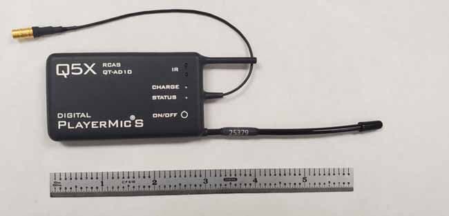
Q5N-QTAD10A15
Mar 16, 2021QT-AD10A15 TRANSMITTER
Equipment Class
DWM - Part 15 Wireless Microphone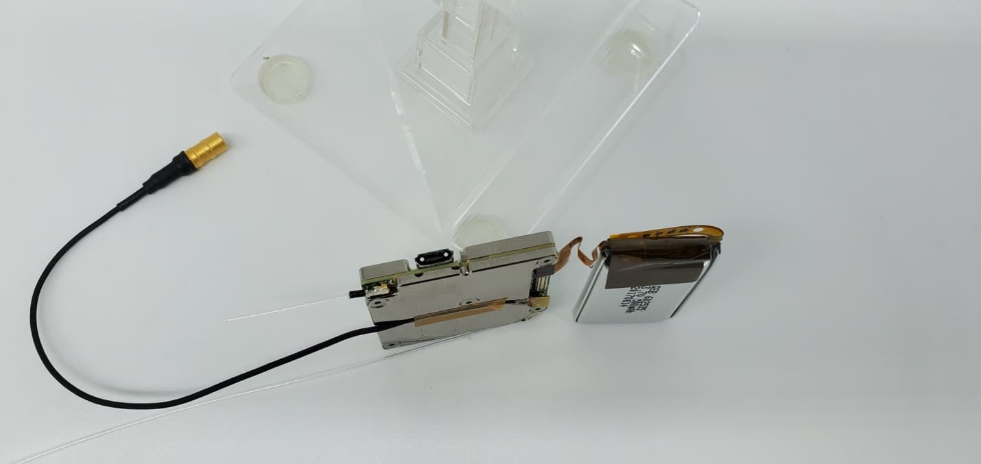
Q5N-QTAD10A
Jul 13, 2020QT-AD10 Module
Equipment Class
TLD - Licensed LPAS Device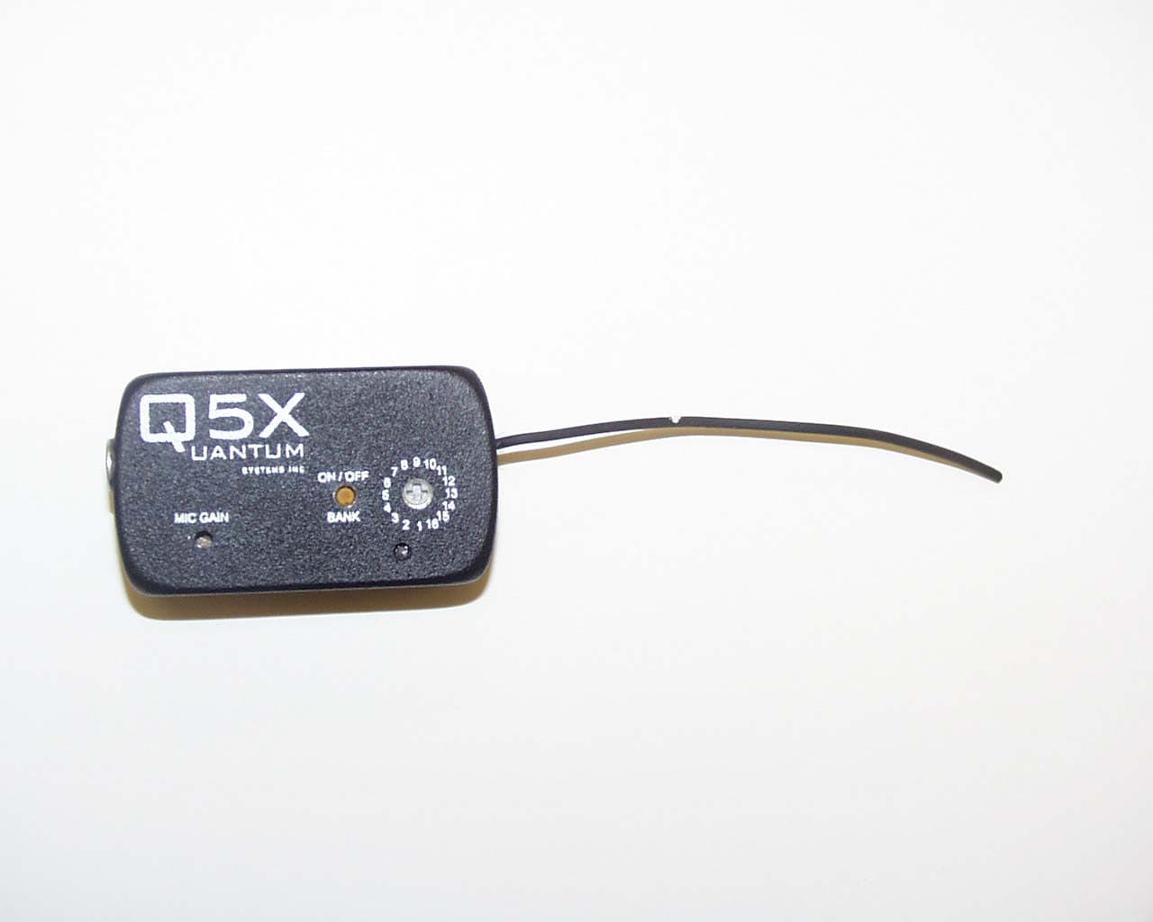
Q5N-QT256
Aug 05, 2003Wireless Microphone, Model QT-256
Equipment Class
TBT - Licensed Broadcast Transmitter Worn on Body