Q5RM3306URF WIRELESS OPTICAL MOUSE
Hahntek Technology Corp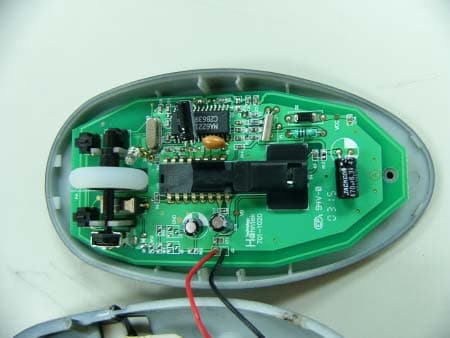
Click to zoom
Application Details
- Equipment Class
- DXX - Part 15 Low Power Communication Device Transmitter
- Date of Grant
- Jun 26, 2003
- Application Purpose
- Original Equipment
- Date of Application
- Jun 26, 2003
- Equipment Note
- RF WIRELESS OPTICAL MOUSE
- Frequency Range
- 27.04500000 - 27.04500000
- Company
- Hahntek Technology Corp
- Country
- Taiwan
Documents & Files
Document Text
Text extracted from the exhibit documents filed with the FCC. Open a document above to read the original.
Users Manual
W i reless Mouse User Manual FCC Notices This device com p lies with part 15 of the FCC rules. Operatio n is subje c t to the f o llow i ng two con d itions : (1)This device m a y not cause harm ful interference, and (2)This dev i ce m u st accept any in terf erence received, includ ing interference that m a y cause undesired operation . N OTE: THE MANUF A CTURER IS NOT RE SPONSIBL E FOR ANY RADIO OR TV INTE RF ERENCE C AUSE D BY UNAUTHORIZED MODIFICA TIONS T O THIS EQUI PMENT . S U CH MODIFICA TIONS COULD VOID THE USER'S AU THORITY T O OPERA T E THE EQUIPME N T . Installation Manualfor Optical RF Wireless/Mouse set Introduction This mouse set is a wireless input device with 27MHz radio frequency. It is plug & play with Windows 98/SE/ME/2000/ XP/NT,without the need of any software installation.If you did install any software for your previous keyboard or mouse ,please remove the mouse driver before use this new device. Receiver Box System Requirement : Related PC compatibles USB ports for mouse Microsoft Windows 98/SE/Me/2000/XP/NT RF Mouse Connect The Receiver : The wireless mouse uses two AAA batterise.(For the best performance, please use only alkaline batteries) Install the Batteries : RF Mouse Remove Cover Two AAA batterise Insert batterise 1.Turn off the computer before connecting the receiver to your computer. 2.For the best performance, place the receiver at least 20 cm (8 inches)away from computer,monitor,and the other devices which will cause radio interference. 3.Working on metallic surface will reduce the RF performance. Avoid placing the receiver on metallic surface. 4.Plug or unplug cable from the computer's USB ports improperly can cause damage to the USB ports and to the computer. 5.If the working range become short when using them,please move the receiver another place. 6.Blinking alarm Red LED at scroll button when batteries failure. 7.For power saving designed. Press anyone of the Left or Right button to start curso after few minutes being no use. This wireless mouse set consists of mouse and receiver. When you do not need to use the wireless mouse for a long period of time, please remove the batteries and store them in a dry place with normal room temperature. Caution : After intstall the batteries and connect the receiver to computer, turn on your computer. If the product can not work or there are multi- products be used. To avoid the interfrernce, you can do the follow the procedures as below to set the ID code. There is an ID button on the back side of the Mouse and another one on the side of the Receiver. 1.Step1:press the ID Flank on Receiver, then press the ID Button on Mouse. The ID code will be set automatically. You can first do any step, then another step. The process of each step must be completed within 5 seconds. 2.Always CH1 at Receiver when set the ID code, otherwise, it can not work. 3.After above process, the Receiver's RF LED will blink, when you move the mouse. This means that the mouse do communicate with the receiver successfully. 4.If you can not see the blinking LED when move the mouse, the mouse can not work propperly.Please re-install the batteries and retry the above set up process. Set The ID Codes RF Mouse ID Set 1.After change the batteries, loose the batteries, or reconnect the Receiver, Please carry out the above procedures to set the ID code again.Otherwise, the unit can not work properly. 2.This product is a signal RF mouse. If two units are used with in the effective working range, radio interference will affect the performance of your input. But set ID code to a different one will minimize the degree of radio interference. Receiver Box RF Signal LED ID Set After successful installation, the mouse can work well with Windows 98/SE/Me/2000/XP/NT, without the need of software driver. Use The Mouse The mouse comes with a scrolling wheel, which can function either as a wheel or as a button. 1.To scroll up, move the wheel forward; to scroll down, move the wheel backward. 2.To use the wheel like a standard mouse middle button, simply click (press down) the wheel button. 1.If your mouse can not work after installation, please check follwings: a).Make sure you have connected the receiver correctly to the computer. The receiver's connectors have been properly plugged onto computer's USB ports. b).Make sure you have inserted the batterise correctly. c).Make sure you have set the ID code properly, as stated above. d).For better performance, place the receiver at least 20 cm (8 inches)away from computer, monitor or other devices which will cause radio interference. Avoid Placing the receiver on metallic surface. e).If without any interference(for example the other computer peripherals), the working distance of the mouse - i.e. the distance between the mouse and receiver, about 5 feet. 2.If your mouse isn't detected by the computer, please check followings: a).Make sure the receiver is plugged onto the right USB port. Don't plug and unplug the receiver's connectors, while the computer is on. b).Make sure your USB ports have the proper configuration. Refer to your computer documents for right configuration. c).You may have other system device(s)(e.g.modem card)that is/are conflicting your mouse. Check the IRQ address setting of these devices, and change the setting as required. Refer to your computer documents to make the changes. 3.If the mouse cursor does not move properly please check followings: a).Check the position of your receiver. Maybe the receiver is too far away. b).Check the large metal devices, such as microwave, electric stove, television, hair dryer....., which may interfere the receiver's radio reception. c).Check the status of the batteries. The batteries maybe near dead. If the mouse does not work after some time of usage, please replace the batterise to see if it can solve the problem. Trouble Shooting WARNING:Take frequent breaks from typing to reduce the risk of the wrists. Caution : Caution : CH1 CH2 Channel SW RF wireless mous…
Text truncated - open the document above for the full version.
Block Diagram
** Block diagram Wireless Mouse I-HSIUNG 030502 210-0001 RF Transmitter bMouse Block Diagram . Move Sensor MK RK LK Scroll Encoder RF Receiver aReceiver Block Diagram . Loop antenna 27.045MHzTx Freq. Loop antenna AAA*2 26.59MHzLocal OSC Freq. USB/ComputerInterfaceDecoder
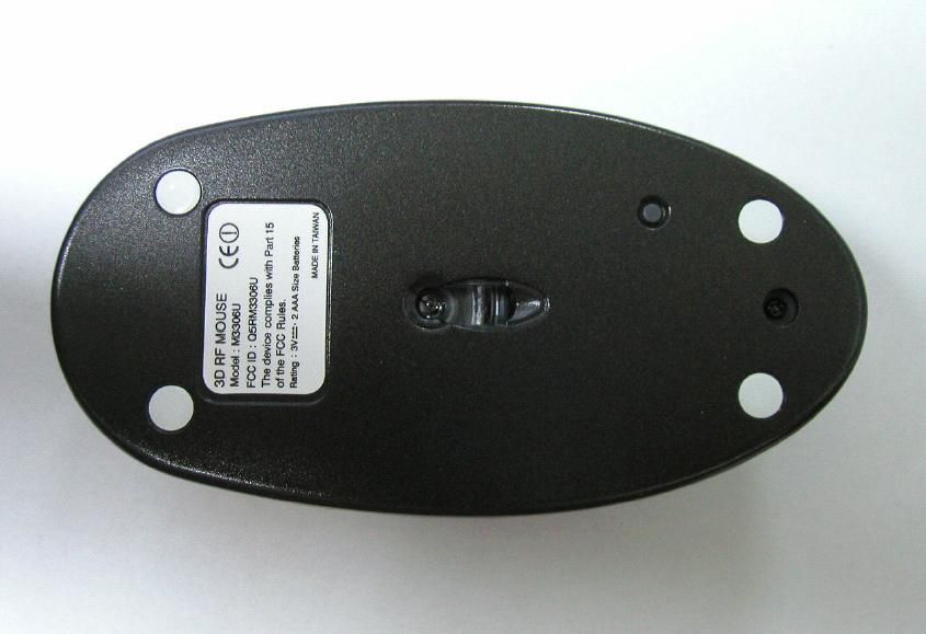
External Photos
External Photos
Internal Photos
Internal Photos
Operational Description
Form Letters1 OPERATIONAL DESCRIPTION The Hanhntek wireless mouse utilizes a 27MHz intentional radiator. The wheels & buttons provide input to IC V741CC60 which in turn provides modulating pulses to the intentional radiator.
Schematics
1234 A B C D 4321 D C B A Title NumberRevisionSize A4 Date:14-May-2003Sheet of File:D:\My Documents\Pcb\M3306U.ddbDrawn By: C12 104 C13 100uF 1 2 J2 From Battery Y1 76.8K C115P C215P R1 5.1M C3 104 C5 33P C6 100P L2 NA Y2 27.042M C8 3P C7 22P C9 47P C10 103 S6 VBS02-03-00 S1RK S2MK S3LK D3R5 D4 ED80 R4560R R2 240K R3 100K R90 D21N5819L1 100uH R7 10R R13 NA R14 10R R815K Y3 ZTA18.432MX C18 104 C17 104 C14 104 C15 470uF C19 10uF C16 10uF R5 1.3M R6 680K 1 2 3 4 5 6 7 8 9 10 11 12 13 1415 16 17 18 19 20 21 22 23 24 25 26 27 28 HAHNTEK U2MA60H221 1 2 3 4 5 6 7 89 10 11 12 13 14 15 16 HAHNTEK U3 ADNS2030 C11 103 C4 10P VCC VDI VCC VCC S5 ENCODER VB VCC L3 LOOP SDIO PD R12 100K R11 100K R15 RES1 R10 100R Q1 2N3906 D1 4148 PJ1 SCD410 1 2 3VOVI G U1XC61C S4ID ** PWB DRILL M3306-PCB I-HSIUNG 030430 1:1 701-1020 3. 2. 1. ** PWB MARK M3306-PCB I-HSIUNG 030430 1:1701-1020 ** PWB SOLDER SCREEN A SIDE M3306-PCB I-HSIUNG 030430 1:1 0.1 () 2. 3. ±mm PWB( 903-2022 )A 1. 701-1020 ** PWB PATTERN B SIDE M3306-PCB I-HSIUNG 030430 1:1 1. 2. 701-1020 ** PWB PATTERN A SIDE M3306-PCB I-HSIUNG 030430 1:1 701-1020 2. 1. ** PWB SOLDER SCREEN B SIDE M3306-PCB I-HSIUNG 030430 1:1 () 3. 2. 1.PWB( 903-2022 )B mm±0.1. . 701-1020
Test Report
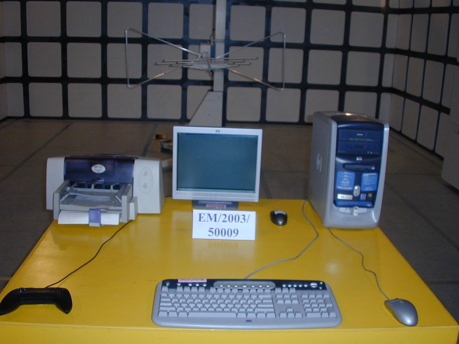
Report No. : ER/2003/50005 Page : 1 of 12 TEST REPORT Product Name : Wireless Optical Mouse Product ID : M3306 Applicant : HAHNTEK TECHNOLOGY CORP. Address of Applicant : No.263,Sec.1,Lung Shou Street, Lu-Chu Hsian 338, Taoyuan Hsien, Taiwan Standards: FCC Part 15 subpart C In the configuration tested, the EUT complied with the standards specified above. The test data, test procedures, and equipment configurations shown in this report were made in accordance with the procedures given in ANSI C63.4(1992). Remarks: This report details the results of the testing carried out on one sample, the results contained in this test report do not relate to other samples of the same product. The manufacturer should ensure that all products in series production are in conformity with the product sample detailed in this report. This report may only be reproduced and distributed in full. If the product in this report is used in any configuration other than that detailed in the report, the manufacturer must ensure the new system complies with all relevant standards. Any mention of SGS Taiwan E&E Services or testing done by SGS Taiwan E&E Services in connection with distribution or use of the product described in this report must be approved by SGS Taiwan E&E Services in writing. Tested by : Alex Hsieh Date : Jun. 15, 2003 Approved by : Robert Chang Date : Jun. 18, 2003 Report No. : ER/2003/50005 Page : 2 of 12 Contents 1. General Information 1.1 Testing Laboratory 3 1.2 Details of Applicant 3 1.3 Description of EUT(s) 3 1.4 Testing Procedure 4 1.5 Testing Method 4 2. Summary of Results 5 3. Instruments List 6 4. Measurements 7 4.1 Radiated emission Limits, general requirement 7 4.2 Fundamental strength limit 9 APPENDIX Photographs of Test Setup 10 Photographs of EUT 11-12 Report No. : ER/2003/50005 Page : 3 of 12 1. General Information 1.1 Testing Laboratory SGS Taiwan Ltd. ( FCC Registration number: 573967 ) 1F, No. 134, Wukung Road, Wuku industrial zone Taipei county , Taiwan , R.O.C. Telephone : +886-2-2299-3279 Fax : +886-2-2298-2698 Internet : http://www.sgs.com.tw 1.2 Details of Applicant Name : HAHNTEK TECHNOLOGY CORP. Address : No. 263, Sec.1, Lung Shou Street, Lu-Chu Hsian 338, Taoyuan Hsien, Taiwan. R.O.C. Contact : Mr. Lin Telephone : +886-3-379-5396 1.3 Description of EUT(s) 1 Product name Wireless Optical mouse 2 Product ID M3306 3 Supply Voltage DC 3.0V , AAA battery X 2 4 Carrier Frequency 27.045 Mhz 5 Modulation Method FSK Report No. : ER/2003/50005 Page : 4 of 12 1.4 Testing Procedure a. The EUT was placed on the top of a rotating table 0.8 meters above the ground at a 3m chamber , then 10 meter open area test site. The table was rotated 360 degrees to determine the position of the highest radiation. b. The EUT was set 3 meters away from the interference-receiving antenna. c. The antenna is a broadband antenna, and its height is varied from one meter to four meters above the ground to determine the maximum value of the field strength. Both horizontal and vertical polarizations of the antenna are set to make the measurement. d. For each suspected emission, the EUT was arranged to its worst case and then the antenna was tuned to heights from 1 meter to 4 meters and the rotatable table was turned from 0 degrees to 360 degrees to find the maximum reading. e. The test-receiver system was set to Peak Detect Function and Specified Bandwidth with Maximum Hold Mode. f. If the emission level of the EUT in peak mode was 10 dB lower than the limit specified, then testing could be stopped and the peak values of the EUT would be reported. Otherwise the emissions that did not have 10 dB margin would be retested one by one using the quasi-peak method or average method as specified and then reported in Data sheet peak mode and QP mode. NOTE: 1. The resolution bandwidth and video bandwidth of test receiver/spectrum analyzer is 120kHz for Peak detection (PK) and Quasi-peak detection (QP) at frequency below 1GHz. 2. The resolution bandwidth and video bandwidth of test receiver/spectrum analyzer is 1 MHz for Peak detection at frequency above 1GHz. 3. The resolution bandwidth of test receiver/spectrum analyzer is 1 MHz and the video bandwidth is 300 Hz for Average detection (AV) at frequency above 1GHz. 1.5 Testing Method The testing standard follows CFR 47, Part 15.247 , and ANSI C63.4 1992. Report No. : ER/2003/50005 Page : 5 of 12 2.Summary of Results subclause Parameter to be measures Verdict Page 15.209 Radiated emission Limits, general requirement PASS 7 15.227 Fundamental Strength Limit PASS 9 Report No. : ER/2003/50005 Page : 6 of 12 3. Instruments List Instrument Model Serial number Calibration date Desktop PC HP Pavillion 723DN/A N/A Spectrum Analyzer R&S FSP 40 100034 Mar. 27, 2003 Antenna Schwarzbeck VULB9163 152 July 01, 2002 EMC Analyzer HP 8594EM 3624A00203 Dec. 13, 2002 EMI Test Receiver R&S ESCS 30 828985/004 Oct. 11, 2002 Report No. : ER/2003/50005 Page : 7 of 12 4. Measurements 4.1 Radiated emission Limits, general requirement SUBCLAUSE 15.209 RBW=120Khz , VBW=120Khz Vertical Report No. : ER/2003/50005 Page : 8 of 12 Horizontal Report No. : ER/2003/50005 Page : 9 of 12 4.2 Fundamental strength limit SUBCLAUSE 15.227 Frequency (Mhz) Read value (dB V) Ant factor (dB) Cable loss (dB) Real value (dB V) Strength limit at 3 meter (dB V/m) 27.044 26.97 11.35 0.24 38.56 80 26.96 20.60 11.35 0.24 32.19 50 27.28 15.19 11.35 0.24 26.78 50 Report No. : ER/2003/50005 Page : 10 of 12 APPENDIX: Photographs of Test Setup <Photos are saved separately> Report No. : ER/2003/50005 Page : 11 of 12 APPENDIX : Photographs of EUT Internal Photo <Photos are saved separately> Report No. : ER/2003/50005 Page : 12 of 12 External Photo <Photos are saved separately>
Contact Information
Applicant
Shiung I Lin(Vice Section)
Test Firm
SGS Taiwan Ltd.Wyse Chiu
Technical Specifications
| # | Rule Parts | Frequency Range | Power Output |
|---|---|---|---|
| 1 | 15C | 27.045 MHz - 27.045 MHz | - |
Other Applications from Hahntek Technology Corp
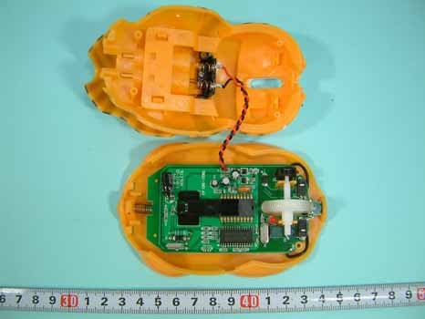
Q5RM3688
May 20, 2005Wireless Mouse
Equipment Class
DXX - Part 15 Low Power Communication Device Transmitter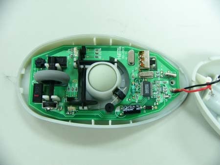
Q5RM3106U
Jun 26, 2003RF WIRELESS MOUSE
Equipment Class
DXX - Part 15 Low Power Communication Device Transmitter