Q639560Iridium 9560 Wi-Fi Access Point with satellite transceiver
Iridium Satellite LLC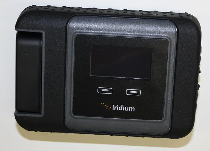
Click to zoom
Application Details
- Equipment Class
- DTS - Digital Transmission System
- Date of Grant
- Mar 31, 2014
- Application Purpose
- Original Equipment
- Date of Application
- Mar 31, 2014
- Equipment Note
- Iridium 9560 Wi-Fi Access Point with satellite transceiver
- Frequency Range
- 2412.00000000 - 2462.00000000
- Company
- Iridium Satellite LLC
- Country
- United States
Documents & Files
Document Text
Text extracted from the exhibit documents filed with the FCC. Open a document above to read the original.
Users Manual
User Manual Iridium GO! ™ Prior to using Iridium GO!, read and understand this User Manual including the safety warnings and information. Failure to do so could result in serious injury or death. Materials are also available online at www.iridium.com or by calling 1.480.752.5155 (Direct); 1.866.497.4348 (Toll Free North America). Thank you for purchasing the state of the art Iridium GO !™ This Iridium GO! product package contains the following: • User Manual (including Safety and Regulatory Information, GEOS Emergency Services Brochure) • Legal Information Booklet (contains limited warranty, including exclusions, disclaimers, limitations of liability and conditions of use, warranty claim process; privacy and data security and software license) ` Iridium GO! User Manual iiiii Iridium GO! User Manual Legal Notices This User Manual provides user information and is provided “as is.” Iridium and its affiliated companies, directors, officers, employees, agents, trustees or consultants (“Iridium”) assume no responsibility for any typographical, technical, content or other inaccuracies in this User Manual. Iridium reserves the right to revise this User Manual or withdraw it at any time without prior notice. You can find the current version of this Iridium GO! User Manual at www.iridium.com. IRIDIUM MAKES NO REPRESENTATIONS, GUARANTEES, CONDITIONS OR WARRANTIES, EITHER EXPRESS OR IMPLIED, INCLUDING WITHOUT LIMITATION, ANY IMPLIED REPRESENTATIONS, GUARANTEES, CONDITIONS OR WARRANTIES OF MERCHANTABILITY AND FITNESS FOR A PARTICULAR PURPOSE, NON- INFRINGEMENT, SATISFACTORY QUALITY, NON-INTERFERENCE, ACCURACY OF INFORMATIONAL CONTENT, OR ARISING FROM A COURSE OF DEALING, LAW, USAGE, OR TRADE PRACTICE, USE, OR RELATED TO THE PERFORMANCE OR NONPERFORMANCE OF ANY PRODUCTS, ACCESSORIES, FACILITIES, SERVICES OR USER INFORMATION, EXCEPT AS EXPRESSLY STATED IN THE LIMITED WARRANTY. ANY OTHER STANDARDS OF PERFORMANCE, GUARANTEES, CONDITIONS AND WARRANTIES ARE HEREBY EXPRESSLY EXCLUDED AND DISCLAIMED TO THE FULLEST EXTENT PERMITTED BY LAW. THIS DISCLAIMER AND EXCLUSION SHALL APPLY EVEN IF THE EXPRESS LIMITED WARRANTY PROVIDED IN THE LEGAL INFORMATION BOOKLET FAILS OF ITS ESSENTIAL PURPOSE. FURTHER, THE LIMITED WARRANTY COVERS Iridium GO! (INCLUDING HARDWARE, SOFTWARE AND/ OR FIRMWARE) AND ACCESSORIES ONLY, AND NO WARRANTY IS MADE AS TO USER INFORMATION AND/ OR COVERAGE, AVAILABILITY OR GRADE OF SERVICE PROVIDED BY IRIDIUM SEPARATELY FOR IRIDIUM SATELLITE SERVICES. IN NO EVENT SHALL IRIDIUM BE LIABLE, WHETHER IN CONTRACT OR TORT OR ANY OTHER LEGAL THEORY, INCLUDING WITHOUT LIMITATION STRICT LIABILITY, GROSS NEGLIGENCE OR NEGLIGENCE, OR IMPLIED WARRANTY, FOR ANY DAMAGES IN EXCESS OF THE PURCHASE PRICE OF Iridium GO! (INCLUDING HARDWARE, SOFTWARE AND/OR FIRMWARE) AND/OR ACCESSORIES AND/OR THE COST OF IRIDIUM SATELLITE SERVICES PROVIDED, NOR SHALL IRIDIUM BE LIABLE FOR ANY DIRECT, INDIRECT, INCIDENTAL, SPECIAL, CONSEQUENTIAL, OR PUNITIVE DAMAGES OF ANY KIND, OR LOSS OF REVENUE OR PROFITS, LOSS OF BUSINESS, LOSS OF PRIVACY, LOSS OF USE, LOSS OF TIME OR INCONVENIENCE, LOSS OF INFORMATION OR DATA, SOFTWARE OR APPLICATIONS OR OTHER FINANCIAL LOSS CAUSED BY Iridium GO! (INCLUDING HARDWARE, SOFTWARE AND/ OR FIRMWARE) AND/OR ACCESSORIES AND/OR THE IRIDIUM SATELLITE SERVICES, OR ARISING OUT OF OR IN CONNECTION WITH THE ABILITY OR INABILITY TO USE Iridium GO! (INCLUDING HARDWARE, SOFTWARE AND/OR FIRMWARE) AND/OR ACCESSORIES AND/OR THE IRIDIUM SATELLITE SERVICES , TO THE FULLEST EXTENT THESE DAMAGES MAY BE DISCLAIMED BY LAW AND REGARDLESS OF WHETHER IRIDIUM WAS ADVISED OF THE POSSIBILITIES OF SUCH DAMAGES. Please refer to the Legal Information Booklet for the Limited Warranty including Exclusions, Disclaimers, Limitations of Liability and Conditions of Use, and Warranty Claim Process. Third Party Information This User Manual might refer to third party sources of information, hardware or software, products or services and/or third party web sites (“third party information”). Iridium does not control, and is not responsible for, any third party information, including without limitation the content, accuracy, copyright compliance, compatibility, performance, trustworthiness, legality, decency, links, or any other aspect of third party information. The inclusion of such third party information does not imply endorsement by Iridium of the third party information. ANY THIRD PARTY INFORMATION THAT IS PROVIDED WITH IRIDIUM’S FACILITIES, SERVICES, PRODUCTS OR USER INFORMATION IS PROVIDED “AS IS.’’ IRIDIUM MAKES NO REPRESENTATIONS, GUARANTEES OR WARRANTIES IN RELATION TO THIRD PARTY INFORMATION AND IRIDIUM SHALL NOT BE LIABLE FOR ANY LOSSES, DAMAGES, LIABILITIES, JUDGMENTS, FINES, AMOUNTS PAID IN SETTLEMENT, EXPENSES OR COSTS OF DEFENSE SUSTAINED IN RELATION TO ANY SUCH THIRD PARTY INFORMATION. Intellectual Property, Trade Secret, Proprietary or Copyrighted Information To protect Iridium proprietary and confidential information and/or trade secrets, this User Manual may describe some aspects of Iridium technology in generalized terms. Iridium products may include copyrighted Iridium and third party software. Any such copyrighted software contained in Iridium products may not be modified, reverse engineered, distributed or reproduced in any manner to the extent provided by law. The purchase of any Iridium products shall not be deemed to grant either directly or by implication or otherwise, any license under copyrights, patents, or patent applications of Iridium or any third party software provider, except for the normal, nonexclusive, royalty free license to use that arises by operation of law in the sale of a product. Content Copyright You are exclusively responsible for the use of Iridium GO!, including proper use of third party copyrighted materials. If you violate these terms you agree to defend, indemnify and hold Iridium harmless with respect to any claims or actions by third parties related to your improper use of copyrighted …
Text truncated - open the document above for the full version.
Users Manual
RG 3 1 6 C A B L E 4 . 0 0 d B i c d B i c 0 ° 0 ° < 0 < 60 ° = 0 ° 3 d B M A X A X I A L R A T I O : R A D I A T I ON C O V E R A G E : P A R T NO . D E S I G N A T I ON : F R E QU E N C Y : I M P E D A N C E : V S W R : P O L A R I Z A T I ON : A L T I T U D E : O P E R A T I N G T E M P : - 40 C T O + 85 C R I G H T H A N D C I RC U L A R < 2 . 0 : 1 50 OH M S 1616 - 1626 M H z W E I G H T : 3 . 7 OUN C E S ( 53 . 3 MM ) 2 . 1 0 ( 1 4 . 5 MM ) . 57 20 , 000 ' NO T E S : UN L E SS O T H E R W I S E S P E C I F I E D A T 1621 - 7 I B - T N C M - 059 - 00 - 00 - I M - R C ONN E C T O R T N C M = T N C M A L E C O L O R G A I N ( 2 db ) I N T E R N A L 00 V O L T A G E P A SS I V E = 00 P A SS I V E = M A G N E T I M = S P E C I F I C A T I ON : T O L E R A N C E S : . XX = . 03 . XXX = . 010 1 . M A T E R I A L : R A D O M E - X E NO Y , H I G H I M P A C T & T E M P . C U S T O M E R L A B E L T N C M C ONN E C T O R 59 . 00 ± 2 . 00 ( 1 . 5 M E T E R ) B L A CK B L A CK B = 2 L A B E L S I Z E , S H A P E A N D C ON T E N T S S U B J E C T T O C H A N G E W I T HOU T NO T I C E . . 030 ( R U BB E R B U M P E R ) R U BB E R B U M P E R 2 I R I D I U M S A T E LL I T E LL C I = C U S T O M E R C A B L E L E N G T H = 059 I N I N C H E S R o H S C O M P L I A N T R o H S R = S T A N D A RD M O D E L = A T 1621 - 7 I B - T N C M - 059 - 00 - 00 - I M - R PAA0601 S/N:XXXX DOW: XX/XX AeroAntenna Technology, Inc. Chatsworth, CA. U.S.A A BC D 5 6 7 8 1 2 3 4 D E S CR I P T I ON S Y M D A T E R E V I S I ON S A PPR O V E D au t ho r i z e d r e p r e s e n t a t i v e o f s a i d C o m pan y . t h i s do c u m e n t w i t hou t t h e e x p r e ss w r i tt e n p e r m i ss i on o f a du t y d i s c l o s e d o r u s e d f o r an y pu r po s e o t h e r t han c on s i d e r a t i on o f PR O PR I E T A R Y NO T I C E : T h i s do c u m e n t c on t a i n s p r op r i e t a r y p r op r i e t a r y i n f o r m a t i on s ha ll b e pub li s h e d , r e p r odu ce d , c op i e d , i n f o r m a t i on o f AA T I n c . n e i t h e r t h e do c u m e n t no r s a i d DR A W N N E X T A SS Y S C A L E . XX = . 01 . XXX = . 005 F R A C T = 1 / 32 A PPR O V E D E N GR M F G S I Z E C A G E C O D E R E V Q . A . 0 U V G 2 NON E S H EE T 1 O F B DR A W I N G NO . T I T L E D O NO T S C A L E T H I S DR A W I N G A LL D I M E N S I ON S A R E I N I N C H E S HO L E D I A . T O L E R A N C E D CB A D I M E N S I ON I N G & T O L E R A N C I N G P E R A S M E Y 14 . 5 M - 1994 T O L E R A N C E S : M A C H I N E D P A R T S 63 S U R FA C E R OU G HN E SS R E M O V E B U RR S A N D BR E A K S H A RP E DG E S : P A R T T O B E C L E A N A N D O I L F R EE DR A W N I N A N G . = 1 / 2 Ae r o A n t e nna T ec hno l og y I n c C H E CK E D M O L D E D P A R T S 32 . 0135 - . 125 . 126 - . 250 . 251 - . 500 . 501 - . 750 + . 004 - . 001 - . 001 + . 005 - . 001 + . 006 - . 001 + . 008 A S9 1 00 C E R T I F I E D C O . A . D E V E R A D . L E VY A . D E V E R A 03 / 02 / 06 I R I D I U M AN T E NNA , R o H S C O M P L I AN T A T 1 62 1 - 7 I B 03 / 07 / 06 02 / 1 3 / 06 B . R U B E N I 03 / 06 / 06 G . S HA R 03 / 02 / 06 AT1621-7I B R E V I S E P E R E C O 8285 07 / 02 / 08 A C A D I : \ C A D \A T 1 62 1 \ - 07 I \A T 1 62 1 - 7 I _ B E . Z E L A Y A 03 / 07 / 06 1 - 7 . 5 d B i c 74 ° < 0 < 82 ° - 4 . 0 d B i c 60 ° < 0 < 74 ° A PP R O V E D D O C U M E N T 7 - 10 - 08
ID Label/Location Info
Below is the format of the device label that appears on the 9560 This label will appear inside the battery cover as shown below
Internal Photos
Top Side Bottom Side
Operational Description
Rev 02 – 25 Feb 2014 9560 – Technical Description The 9560 device is a standalone transceiver for the Iridium network, which offers a Wi-Fi connection to a user’s smart-phone device, or Laptop. The device has an integrated Iridium 9523 L-band transceiver, GPS receiver, and antennas. The device operates from an internal battery that is chargeable via the USB connector. The user has an App running on their smart phone that allows them to place satellite calls, send/receive SMS’s and make a data call. Their Smartphone/laptop connects to the 9560 via a Wi-Fi and then the 9560 routes that call via the Iridium satellite network. Up to five separate users can be connected via Wi-Fi with the 9560 although only a single user can be in a call at one time. The processor is the central element of the 9560 system and is running a Linux operating system with adequate performance requirements for a SIP server and other web services via WIFI. The processor used in the 9560 is a Freescale iMX280 which contains a ARM926EJ-S core capable of running at 454MHz. It supports external DDR2 SDRAM and NAND flash. It also has the following built-in interfaces which are required to interface with other peripherals in the 9560. - SDIO interface for WIFI module - UARTS for GPS and Iridium 9523 transceiver module - SAIF audio interface for Iridium 9523 transceiver module - I2C Interface for OLED display and CODECs - ADC interface for various voltage measurement including temperature sensor and hardware revision and modification control - GPIO for User Interface buttons and control signals etc - Built-in DC-DC converter for generating 3V3 for external peripherals and 1V8 for DDR2 SDRAM Both the Iridium 9523 transceiver (FCC ID: Q639523) and Bluegigia WF111 (FCC ID: QOQWF111 with integrated antenna) modules have FCC modular approvals.
RF Exposure Info
Page 1 of 6 MPE Calculation Report Report Number: M131204-MPE Test Sample: Iridium Wi-Fi Access Point with satellite transceiver Model Number: 9560 Tested For: Iridium Satellite, LLC Date of Issue: 20 th March 2014 EMC Technologies Pty Ltd reports apply only to the specific samples tested under stated test conditions. It is the manufacturer’s responsibility to assure that additional production units of this model are manufactured with identical electrical and mechanical components. EMC Technologies Pty Ltd shall have no liability for any deductions, inferences or generalisations drawn by the client or others from EMC Technologies Pty Ltd issued reports. This report shall not be used to claim, constitute or imply product endorsement by EMC Technologies Pty Ltd. EMC Technologies Pty Ltd ABN 82 057 105 549 176 Harrick Road Keilor Park Victoria Australia 3042 Ph: + 613 9365 1000 Fax: + 613 9331 7455 email: [email protected] EMC Technologies Pty Ltd ABN 82 057 105 549 57 Assembly Drive Tullamarine Victoria Australia 3043 Ph: + 613 9335 3333 Fax: + 613 9338 9260 email: [email protected] Report No.: M131204-MPE Page 2 of 6 FCC Maximum Permissible Exposure (MPE) Calculation Iridium Wi-Fi Access Point with Satellite Transceiver, Model: 9560 Report Number: M131204-MPE 1.0 GENERAL INFORMATION Test Sample: Iridium Wi-Fi Access Point with satellite transceiver Model Number: 9560 IMEI Number: 300325010001030 FCC ID: Q639560 IC ID: 4629A-9560 Hardware Version: REV.03 Software Version: 0.25.121 Serial Number: 1003 Device Category: Mobile Transmitter Test Device: Production Unit / Prototype Sample RF exposure Category: General Public/Unaware user Tested for: Iridium Satellite, LLC Address: 1750 Tysons Blvd Suite 1400 McLean, VA 22102 Contact: Hermon Pon, VP Technology Development & Network Engineering Phone: +1.703.287.7434 Email: [email protected] Test Standard/s: 447498 D01 General RF Exposure Guidance v05r01 Calculation Summary: A MPE calculation was performed according to 47CFR2.1091 for the Iridium Wi-Fi Access Point with satellite transceiver, model 9560. The maximum percentage of MPE was 21.7% occurring at the minimum separation distance from device and 27.1% at minimum separation distance from external antenna. Test Dates: 20 th March 2014 Test Officer: Mahan Ghassempouri Authorised Signature: Stephen Phillips Report No.: M131204-MPE Page 3 of 6 2.0 DESCRIPTION OF DEVICE 2.1 Description of Test Sample The device assessed was an Iridium Wi-Fi Access Point with satellite transceiver, Model: 9560 operating in 1616 MHz to 1626 MHz frequency band and also in 2450 MHz WLAN frequency band. It has fixed length integral antennas. It will be referred to as the device under test (DUT) throughout this report. DUT can also be used with an external antenna for satellite communication with the gain of no more than 3 dBi. Integral antenna and external antenna cannot be used simultaneously. Table: DUT Parameters Number of antennas 3 Antenna 1 transmit frequency (WiFi) 2450 MHz Antenna 1 gain 0 dBi Antenna 1 input power 0.082 W Antenna 2 transmit frequency (Satellite) 1621.12 MHz Antenna 2 gain 1.8 dBi Antenna 2 input power 0.682 W External antenna frequency (only for satellite communication) 1621.12 MHz External antenna gain 3.00 External antenna input power 0.682 2.2 Transmitting Antennas Location DUT includes two transmitting antennas, one for satellite communication and the other for WiFi. Dimensions of DUT is 12 cm x 8 cm. Position of transmitting antennas in (X, Y) coordinates is shown in Figure 1. For WiFi and satellite antenna positions are (4,-3.3) cm and (-4.5, 1.5) cm, respectively. DUT can be used with external antenna (for satellite communication) of the gain less than or equal to 3 dBi. According to device architecture, external satellite antenna and integral satellite antenna cannot transmit simultaneously. Two calculations are done: 1. WiFi antenna positioned at (4,-3.3) cm and satellite (integral) antenna positioned at (-4.5, 1.5) cm 2. External antenna investigated separately Figure 1: Location of transmitting antennas Report No.: M131204-MPE Page 4 of 6 2.3 Limits As specified in table 1B of 47 CFR 1.1310 limits for occupational/controlled exposure and general public/uncontrolled exposure are as follows: Frequency (MHz) Power Density (mW/cm 2 ) General public/Uncontrolled 1500-100000 1 Occupational/Controlled 1500-100000 5 2.4 Device Category According to the manufacturer declaration and based on DUT intended use, DUT is considered as Mobile device. For purposes of 47 CFR 2.1091, a mobile device is defined as a transmitting device designed to be used in other than fixed locations and to generally be used in such a way that a separation distance of at least 20 centimetres is normally maintained between the transmitter's radiating structure(s) and the body of the user or nearby persons. In this context, the term “fixed location” means that the device is physically secured at one location and is not able to be easily moved to another location. Transmitting devices designed to be used by consumers or workers that can be easily re-located, such as wireless devices associated with a personal computer, are considered to be mobile devices if they meet the 20 centimetre separation requirement. 3.0 Method of Calculation Calculation is done according to KDB 447498 D01 v05r02 and using excel sheet provided by FCC at http://transition.fcc.gov/oet/ea/presentations/files/oct05/MPE-mobile.xls Report No.: M131204-MPE Page 5 of 6 4.0 Calculation Results 4.1 Basic Application without External Antenna Calculation results are shown in below table and graphical presentation of %MPE Contour is shown in Figure 2. Antenna No. Total 1 2 Frequency (MHz) - 2450 1621.12 MPE General public/Uncontrolled Limit (mW/cm 2 ) - 1.00 1.00 Max % MPE 21.7 1.6 20.5 Power (W) 0.764 0.082 0.682 Antenna Gain (dBi) - 0.00 1.80 EIRP (W) 1.11 0.082 1.032 X (cm) - 4.4 -4.5 Y (cm) - -3.3 1.5 Figure 2: % MPE Contour for basic applicati…
Text truncated - open the document above for the full version.
Test Report
A RADIO TEST REPORT FOR Iridium Satellite LLC ON Iridium 9560 Wi-Fi Access Point with satellite transceiver DOCUMENT NO. TRA-015542-03-47-00-D Total Number of Pages: 43 TRaC Wireless Test Report : TRA-015542-03-47-00-D Applicant : Iridium Satellite LLC Apparatus : Iridium 9560 Wi-Fi Access Point with satellite transceiver Specification : FCC CFR47 Part 15(c) & Part 25 Purpose of Test : Verification of emission profile Authorised by : : Radio Product Manager Issue Date : Authorised Copy Number : PDF TRaC Global Test Report: TRA-015542-03-47-00-D 3 Contents Section 1: Introduction 4 1.1 General 4 1.2 Tests Requested By 5 1.3 Manufacturer 5 1.4 Apparatus Assessed 5 1.5 Test Result Summary 6 1.6 Notes Relating To the Assessment 7 1.7 Deviations from Test Standards 8 Section 2: Measurement Uncertainty 9 2.1 Measurement Uncertainty Values 9 Section 3: Modifications 11 3.1 Modifications Performed During Assessment 11 Appendix A: Formal Emission Test Results 12 A1 Radiated Electric Field Emissions 13 Appendix B: Supporting Graphical Data 15 Appendix C: Additional Test and Sample Details 34 Appendix D: Additional Information 39 Appendix E: Photographs and Figures 40 TRaC Global Test Report: TRA-015542-03-47-00-D 4 Section 1: Introduction 1.1 General This report contains an assessment of an apparatus based upon tests carried out on samples submitted to the Laboratory. Test performed by: TRaC Global [ ] Unit E South Orbital Trading Park Hedon Road Hull, HU9 1NJ. United Kingdom. Telephone: +44 (0) 1482 801801 Fax: +44 (0) 1482 801806 TRaC Global [X] Unit 1 Pendle Place Skelmersdale West Lancashire, WN8 9PN United Kingdom Telephone: +44 (0) 1695 556666 Fax: +44 (0) 1695 577077 Email: [email protected] Web site: http://www.tracglobal.com Tests performed by: A. Tosif - D. Winstanley Report author: A. Tosif - D. Winstanley This report must not be reproduced except in full without prior written permission from TRaC Global. TRaC Global Test Report: TRA-015542-03-47-00-D 5 1.2 Tests Requested By This testing in this report was requested by: Iridium Satellite, LLC 1750 Tysons Blvd Suite 1400 McLean, VA 22102 +1.703.287.7434 [email protected] 1.3 Manufacturer Iridium Satellite, LLC 1750 Tysons Blvd Suite 1400 McLean, VA 22102 +1.703.287.7434 [email protected] 1.4 Apparatus Assessed The following apparatus was assessed (i.e. tested for intermodulation products) between 9 th November 2013 – 14 th November 2013 Iridium 9560 Wi-Fi Access Point with satellite transceiver The above device is a wireless access point that connects to the Iridium Satellite network to allow multiple users within WiFi range to the EUT to access a Wide Area Network for data and voice calls. TRaC Global Test Report: TRA-015542-03-47-00-D 6 1.5 Test Result Summary Full details of test results are contained within Appendix A. The following table summarises the results of the assessment. The statements relating to compliance with the standards below apply ONLY as qualified in the notes and deviations stated in sections 1.6 to 1.7 of this test report. Full details of test results are contained within Appendix A. The following table summarises the results of the assessment. Test Type Regulations Measurement standard Result Co-located Radiated Emissions <1000MHz Title 47 of the CFR: Part 15 Subpart (c) 15.247 Title 47 of the CFR: Part 25 Section 25.202 (f) ANSI C63.10:2009 Pass Co-located Radiated Emissions >1000MHz Title 47 of the CFR: Part 15 Subpart (c) 15.247 Title 47 of the CFR: Part 25 Section 25.202 (f) ANSI C63.10:2009 Pass . Abbreviations used in the above table: CFR : Code of Federal Regulations ANSI : American National Standards Institution REFE : Radiated Electric Field Emissions PLCE : Power Line Conducted Emissions TRaC Global Test Report: TRA-015542-03-47-00-D 7 1.6 Notes Relating To the Assessment With regard to this assessment, the following points should be noted: The results contained in this report relate only to the items tested and were obtained in the period between the date of initial receipt of samples and the date of issue of the report. The apparatus was set up and exercised using the configurations, modes of operation and arrangements defined in this report only. Particular operating modes, apparatus monitoring methods and performance criteria required by the standards tested to have been performed except where identified in Section 1.7 of this test report (Deviations from Test Standards). For emissions testing, throughout this test report, “Pass” indicates that the results for the sample as tested were below the specified limit (refer also to Section 2, Measurement Uncertainty). All testing with the exception of testing at the Open Area Test Site was performed under the following environmental conditions: Temperature : 15 to 23 °C Humidity : 63 to 73 % Barometric Pressure : 86 to 106 kPa Note that temperature and humidity conditions can be found in the relevant test results appendix A. All dates used in this report are in the format dd/mm/yy. TRaC Global Test Report: TRA-015542-03-47-00-D 8 1.7 Deviations from Test Standards No deviations were made from test standards TRaC Global Test Report: TRA-015542-03-47-00-D 9 Section 2: Measurement Uncertainty 2.1 Measurement Uncertainty Values For any test data recorded in accordance with note (iii) of Section 2.1 the following measurement uncertainty was calculated: Radio Testing – General Uncertainty Schedule All statements of uncertainty are expanded standard uncertainty using a coverage factor of 1.96 to give a 95% confidence where no required test level exists. [1] Adjacent Channel Power Uncertainty in test result = 1.86dB [2] Carrier Power Uncertainty in test result (Power Meter) = 1.08dB Uncertainty in test result (Spectrum Analyser) = 2.48dB [3] Effective Radiated Power Uncertainty in test result = 4.71dB [4] Spurious Emissions Uncertainty in test result = 4.75dB [5] Maximum frequency error Uncertainty in test result (Power Meter) = 0.113ppm Uncertainty …
Text truncated - open the document above for the full version.
Test Report
REPORT ON THE EMC TESTING OF A IRIDIUM SATELLITE LLC IRIDIUM 9560 WI-FI ACCESS POINT WITH SATELLITE TRANSCEIVER WITH RESPECT TO THE UNINTENTIONAL RADIATOR REQUIREMENTS OF THE FCC RULES CFR 47: OCTOBER 2010 PART 15.107 AND 15.109 CLASS B LIMIT REPORT ON THE EMC TESTING OF A IRIDIUM SATELLITE LLC IRIDIUM 9560 WI-FI ACCESS POINT WITH SATELLITE TRANSCEIVER WITH RESPECT TO THE UNINTENTIONAL RADIATOR REQUIREMENTS OF THE FCC RULES CFR 47: OCTOBER 2010 PART 15.107 AND 15.109 CLASS B LIMIT TEST DATE: 04 th September - 10 th October 2013 Report Compiled By: ....................................... Sean Walker Approved By: .................................................................................................... Antony Lowry Date: ..............................19 th December 2013........................................... Distribution: Copy 1: Iridium Satellite LLC Copy 2: TRaC Global Ltd Disclaimers: [1] THIS DOCUMENT MAY BE REPRODUCED ONLY IN ITS ENTIRETY AND WITHOUT CHANGE [2] THE RESULTS CONTAINED IN THIS DOCUMENT RELATE ONLY TO THE ITEM(S) TESTED Report Number: TRA-015542-35-01C Issue: 3 Copy Number: PDF RF088 iss17 TRA-015542-35-01C Page 3 of 37 SUMMARY TEST REPORT NO: TRA-015542-35-01C TRaC WORKS ORDER: TRA-015542-00 PURPOSE OF TEST: Radio Frequency Interference Emissions Verification TEST SPECIFICATION: FCC RULES CFR 47: OCTOBER 2010 PART 15.107 AND 15.109 CLASS B LIMIT EQUIPMENT UNDER TEST: Iridium 9560 Wi-Fi Access Point with satellite transceiver TEST RESULT: Measured as Compliant, Class B Given the modifications (if any) described in Section 5 (Note uncertainty values in Appendix B) CLIENT: Iridium Satellite LLC CLIENT CONTACT: Mr Hermon Pon Tele: +1.703.287.7434 E-mail: [email protected] ORDER NO: 62895 TESTED BY: Sean walker DATE OF TEST: 04 th September - 30 th September 2013 The results contained herein relate only to the items tested. RF088 iss17 TRA-015542-35-01C Page 4 of 37 CONTENTS 1. INTRODUCTION 2. SYSTEM UNDER TEST 2.1 Equipment Under Test 2.2 System Equipment 2.3 Modes of Operation of EUT During Testing 2.4 Block Diagram of EUT Configuration 3. TEST CONDITIONS 3.1 Power Line Conducted Emissions 3.2 Radiated E-Field Emissions 4. LIST OF MODIFICATIONS 5. CONCLUSIONS 5.1 Result of Testing 5.2 Conformity in Production APPENDIX A SCAN DATA GRAPHS A1 POWER LINE CONDUCTED EMISSIONS A2 RADIATED E-FIELD EMISSIONS APPENDIX B MEASUREMENT UNCERTAINTY APPENDIX C PHOTOGRAPHS C1 POWER LINE CONDUCTED EMISSIONS C2 RADIATED E FIELD EMISSIONS APPENDIX D ADDITIONAL INFORMATION RF088 iss17 TRA-015542-35-01C Page 5 of 37 1 INTRODUCTION This report presents the results of EMC tests carried out on equipment type Iridium 9560 Wi-Fi Access Point with satellite transceiver, in accordance with the FCC Rules CFR 47: October 2010 Part 15.107 and 15.109 Class B Limit The testing was carried out for Iridium Satellite LLC by TRaC Global Ltd, an independent test house, at their EMC test facility located at Skelmersdale, West Lancashire, England. TRaC Global Ltd is appointed as a CAB & TCB for FCC part 15 testing. The test site is FCC listed and is calibrated as recommended in Document ANSI C63.4: 2003 This report also details the configuration of the equipment under test, the test methods used and any relevant modifications where appropriate. The equipment and peripherals were operated as specified in ANSI C63.4: 2003 Document. RF088 iss17 TRA-015542-35-01C Page 6 of 37 2 SYSTEM UNDER TEST 2.1 Equipment Under Test (EUT) Iridium 9560 Wi-Fi Access Point with satellite transceiver Manufacturer: [email protected] Build Level: Production Serial No: APM01035 Software Revision: Ver. 22.37 Highest frequency generated or used in the EUT or on which the EUT operates or tunes: 2.4GHz 2.2 Support Equipment 1. A Laptop 2. An External aero antenna technology inc antenna. Model No: AT1621-142BW-TNCF-000-00-00-NM-K S/N: 53172 2.3 Modes of Operation of EUT During Testing The EUT will operate in two modes: • Active call and loud speaker via external antenna • Charging mode The call is made from the support laptop via 3XC sip client to the phone in the monitoring room, an audio file is on repeat through out the test and monitored for any signs of degradation. The charging mode is monitored by the display icon and monitored via current draw on the AC side. RF088 iss17 TRA-015542-35-01C Page 7 of 37 2.4 Block Diagram of EUT Configuration NOTE: All cables unshielded unless otherwise stated. Cable lengths are as shown in diagram. EUT Mains Power Supply 120V, 60Hz 4core shielded 1.2 metre Coax shielded 10 metre External Antenna Laptop Support Equipment Mains Adapter 5V 2.1A Test message via 2.4GHz WiFi Test message via iridium satellite to PSTN network and phone line RF088 iss17 TRA-015542-35-01C Page 8 of 37 3 TEST CONDITIONS 3.1 Conducted Emissions 3.1.1 General This test measures conducted noise that may be present on an EUT’s power supply cable. This test ensures the protection of broadcast and telecommunication services used in the vicinity of the EUT. The test setup used complies with all the dimension requirements set out in ANSI C63.4: 2003. 3.1.2 Conducted Emission Test Parameters Frequency Range 150kHz – 30MHz Frequency Step Size 5kHz Measurement Bandwidth 9kHz Detectors Peak (scan) Quasi-peak (final measurements) Average (scan & final measurements) Quasi-peak Detector Dwell Minimum 2s per frequency point EUT Measurement Height 0.8m Insulated Table Line Voltage 120V Line Frequency 60Hz 3.1.3 Test Equipment The following test equipment was used: Type of Equipment Maker/ Supplier Model Number Serial Number TRaC Number Actual Equipment Used Calibration Due Date Receiver Rhode & Schwarz ESHS20 837960/003 237 Receiver Rhode & Schwarz ESHS10 844077/019 353 3-Phase LISN/AMN Schwarzbeck NSKL8128 8128151 207 LISN/AMN Teseq ISN T800 34437 UH446 15/08/2014 Receiver Rhode & Schwarz ESHS10 830051/001 UH03 08/05/2014 LISN/AMN Rhode & Schwarz ESH3-Z5 863906/018 UH05 N-Type Cable TRaC N/A N/A UH21 10/08/2014 LISN/AMN …
Text truncated - open the document above for the full version.
Contact Information
Applicant
Kathy Morgan(Chief Legal Officer)
Test Firm
Element Materials Technology Warwick LtdStewart Barrowclough
Technical Specifications
| # | Rule Parts | Frequency Range | Power Output |
|---|---|---|---|
| 1 | 15C | 2.41 GHz - 2.46 GHz | 82.00 mW |
Other Applications from Iridium Satellite LLC
Q639604
Apr 09, 2026Hybrid LTE-M Cellular + IRIDIUM Satellite + GNSS module for IoT
Equipment Class
TNB - Licensed Non-Broadcast Station TransmitterQ639704
Dec 08, 2024Data satellite transceiver module for use with the Iridium satellite communications network.
Equipment Class
TNB - Licensed Non-Broadcast Station TransmitterQ639690
Aug 18, 2020Standalone satellite device with Java application programming environment. Includes internal power supply, Iridium Short Burst Data Transceiver, GNSS, BLE, I/O, RS232, RS485, CAN.
Equipment Class
TNB - Licensed Non-Broadcast Station Transmitter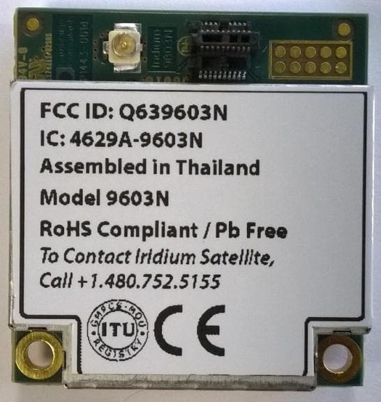
Q639603N
Aug 26, 2014Short Burst Data Transceiver
Equipment Class
JBP - Part 15 Class B Computing Device Peripheral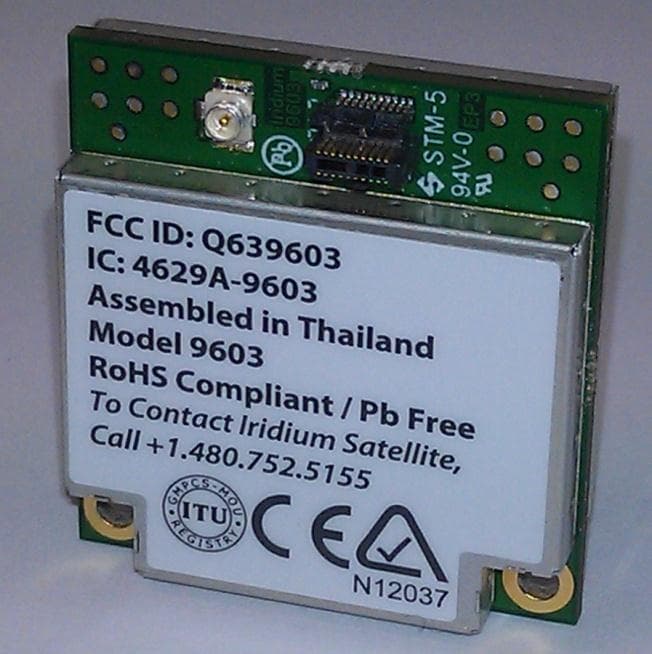
Q639603
Jul 02, 2012Short Burst Data Transceiver
Equipment Class
TNB - Licensed Non-Broadcast Station Transmitter