Q6N199ELBRC Pterosaur (Transmitter)
EDU Science Co., Ltd.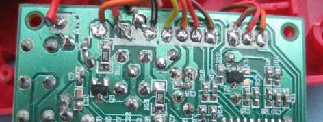
Click to zoom
Application Details
- Equipment Class
- DXX - Part 15 Low Power Communication Device Transmitter
- Date of Grant
- Jun 07, 2007
- Application Purpose
- Original Equipment
- Date of Application
- Jun 07, 2007
- Equipment Note
- RC Pterosaur (Transmitter)
- Frequency Range
- 49.85800000 - 49.85800000
- Company
- EDU Science Co., Ltd.
- Country
- Hong Kong
Documents & Files
Document Text
Text extracted from the exhibit documents filed with the FCC. Open a document above to read the original.
Users Manual
Radio Control AP_37328_instruction sheet : 210mm X 297mm (English) Do not mix old and new batteries. Do not mix alkaline, standard (carbon zinc), or rechargeable (nickel-cadmium) batteries. RC Pterodactyl Set includes: EPP Pterodactyl (Fig.1) Controller/charger with built-in charging wire (Fig.2) WARNING: Always TURN OFF when not flying! Propeller Antenna Charging to a plug Left leverRight Lever Trimmer Charging LEDON/ OFF switch Flying Preparation: Battery Installation – Transmitter (Fig. 4) 1. Unscrew the battery door with a Phillips head screwdriver 2. Insert 6 x AA alkaline batteries in the battery compartment following the polarity indication 3. Replace the battery door Battery Charging: Your Pterodactyl should always be "Power-Off" when it is not in use. Detach the connecting wire from the controller unit and plug into the socket on Pterodactyl. The green LED will light up and turn off when the built-in battery is fully charged in around 30 minutes. A fully charged battery can serve up to 10 minutes flight time.* Playground and Weather Selection: Indoor: Playing in a hall is recommended, keeping away from electric fans and air conditioners. Outdoor: Pterodactyl will fly better on a sunny day with calm wind or slight breeze. We suggest playing on grass to protect your Pterodactyl from crashing on hard rock or ground. Cautions: Your Pterodactyl will be blown way under strong wind because of its light weight. Do not launch your Pterodactyl when it is raining, snowing, or near high power cables. There’s something in the sky and it’s not a bird or a plane – in fact, it’s not from our world at all – it’s a Pterodactyl! The radio-controlled replica of this graceful pre-historic reptile takes flight with kids controlling the action, using the fully-directional hand-held device. The controller choreographs the Pterodactyl's swooping dives and tight turns. With a little practice, kids can catch the wind currents and the RC Pterodactyl will fly for up to 30 minutes. About Pterosaurs The Pterodactyl, also referred to as Pterosaur meaning “winged lizard,” was the first vertebrate to evolve into flight. These small flying reptiles lived during the Mesozoic period 250 million years ago and ranged from the size of small birds to have sweeping wing spans of up to 60 feet. Their skeletons were made of hollow bones covered with leathery membranes stretching from the chest out to what is imagined to have been an extremely lengthened fourth finger. Pterodactyls had sizable brains and used their intelligence and sharp eyesight to hunt prey while in flight, mostly fish and other sea creatures. Pterodactyl Product and Battery Requirement: EPP Pterodactyl size: 340 (L) x 200 (W) x 85.3 (H) in mm Pterodactyl: Rechargeable battery built in with rechargeable battery Charger/Controller: Requires 6 x AA batteries (not included) #37328 © 2007 Discovery Communications, Inc. All rights reserved. Animal Planet logo and Animusings are trademarks of Discovery Communications, Inc., www.animalplanet.com © Copyright 2007 Geoffrey, Inc., a subsidiary of Toys “R” Us, Inc. Made in China Distributed in the United States by Toys “R” Us, Inc., Wayne, NJ 07470 Distributed in Australia by Toys “R” Us (Australia) PTY Ltd., Regents Park NSW 2143 www.toysrus.com 1 2 5 4 3 Fig. 1Fig. 2 Fig. 4 Fig. 5 Fig. 6 ON OFF POWER CHARGETRIM Flying Your Pterodactyl: 1. Set the ON/OFF switch on your Pterodactyl to ON. MAKE SURE THE TRANSMITTER IS “OFF” when turning on the Pterodactyl. 2. Screw in and extend the telescopic antenna on transmitter. 3. Set the left lever on transmitter to MINIMUM throttle, then set it to ON. 4. Make sure the Pterodactyl can go nearly straight: - Set the right lever on transmitter to neutral position, then push the throttle in the middle to drive the Pterodactyl and hand throw the Pterodactyl out to observe its flying trend. - Tune the steering trimmer to left when Pterodactyl has the trend to fly right or tune the trimmer to right when it goes left. - Maneuver the left lever to MINIMUM (downward) to stop the Pterodactyl. (Fig. 4) 5. Make sure to let the Pterodactyl face to the wind when you throw it. It is important that you maneuver throwing it horizontally. (Fig. 5) 6. Set the right lever in its neutral position, then push the throttle to MAXIMUM (upward) to drive the Pterodactyl and hand throw it out for flight. (Fig.6) 7. When your Pterodactyl can fly steadily, you can maneuver the right lever control to turn left or right. 8. You can make a safe landing by turning your Pterodactyl to face the wind, then throttle the left lever downward. Maintenance If your Pterodactyl encounters minor damage, you can fix it with pressure sensitive tape. If your Pterodactyl encounters a broken or spoiled propeller, it can be replaced with the spare propellers provided. (Fig.7 & 8) Safe Battery Usage: · Batteries should be installed and replaced by adults. · Do not dispose off batteries in fire. Battery may explode or leak. · Do not mix old and new batteries. · Do not mix alkaline, standard (carbon zinc) or rechargeable (Nickel-cadmium) batteries. · Only batteries of the same or equivalent type as recommended are to be used. · Insert batteries according to diagram for correct polarity. · Remove dead batteries from the toy. · Do not short-circuit supply terminals. · Do not charge non-rechargeable batteries. The device complies with Part 15 of the FCC rules. Operation is subject to the following conditions: (1) this device may not cause interference, and (2) this device must accept any interference received, including interference that may cause undesired operation. Wind direction 6 + AA x 6 not included Li-Po x 1 included Power LED Fig. 7 Fig.8 concave side convex side Take out the broken or spoiled propeller Insert the new propeller into the axle carefully ON/ OFF switch Charging shocket Fig. 3Fig. 4 Back of transmitter 1.5V "AA" LR6 1.5V "AA" LR6 1.5V "AA" LR6 1.5V "AA" LR6 1.5V "AA" LR6 1.5V "AA" LR6 TRIM POWER CHARGE TRIM POW…
Text truncated - open the document above for the full version.
External Photos
Top View of TX Bottom View of TX
ID Label/Location Info
This device complies with part 15 of the FCC Rules. Operation is subject to the following two conditions: (1) This device may not cause harmful interference, and (2) this device must accept any interference received, including interference that may cause undesired operation. FCC IDQ6N199ELB 49 MHz
Internal Photos
Internal photo of TX-1 Internal photo of TX-2 Internal photo of TX-3 Internal photo of TX-4
Operational Description
EL199 Pterosaur 49.820 ~ 49.900MHz Transmitter Operation Description Mar 10, 2007 Confidential Page 1 of 3 The Microprocessor (U1, Figure 1) reads input commands (SW2/SW3/W2/W3,Figure 1),and then encodes them to digital codes. The codes are sent to RF oscillator via pin 6 of U1, Q6, Q7 and then modulates 49.820 ~ 49.900 MHz carry frequency signal via Q1 (Figure 2) to achieve AM signal . Figure 1 The Radio Frequency of the transmitter is based on standard 49MHz AM citizen’s band. It generates low power 49.820 ~ 49.900MHz AM carrier frequency via major components of Q1, Y1, L1, C5, R4, R3 and R28 etc. (Figure 2). Please note that the value of the components may vary. Please see the attached schematics for more detail. EL199 Pterosaur 49.820 ~ 49.900MHz Transmitter Operation Description Mar 10, 2007 Confidential Page 2 of 3 Figure 2 The AM signal (via capacitor C3) is passed to RF amplifier (Figure 3,Q2,C8,R9,and L2), which amplifies the signal and then couples the signal into the antenna (ANT1) via components C4,C6,L4,C7 and L3. EL199 Pterosaur 49.820 ~ 49.900MHz Transmitter Operation Description Mar 10, 2007 Confidential Page 3 of 3 Figure 3
Schematics
11 22 33 44 55 66 77 88 DD CCBB AA Title Number Revision Size A3 Date: 1/12/2007 Sheet of File: H:\EED\..\EL190TX1_SCH.SchDoc Drawn By: R34.7k C847p C433p C710p R922R C333p ANT1 R4 180R Y1 49.820~49.900MHz R710K C2104 L31.0uH C656P C533p L21.0uH L11.0uH VCC 123456789 101112131415161718 U1 R1610K C11104 Vref C13104W210K R12220R R1339K C15104 VDD R18330R R19220R VDD U2KA431 Vref W310K SW2 R Chg RGND BatV VDD R1100R C1102 BT3 3.7V,LI-PO Q4S8550 Q3 S8550 D11N4007 R112R/1206 Chg Q58050D R15 2.2k R142.2k VCC R8 10K R6100kR10100k C10 104 BatV BT1 4.5V BT2 4.5V VDD VCC 2 31 SW1ON/OFF TxD VDD C19104 C17 100uF/16V C18104 TRIM TRIM R172.2k SW3 L R2 100R Q28050D Q1C380Y R212R/1206 R2410K R2310K VDD Q68050D L4 0.56uH Q7S8550 R264.7k R2710k TxD VCC P64 P64 D2Green D3Red C22102 R284.7k Vref VCC L5 1.0uH
Test Report
Report No.:SZT070508118003 Page 1 of 22 ELECTROMAGNETIC EMISSIONS COMPLIANCE REPORT INTENTIONAL RADIATOR CERTIFICATION TO FCC PART 15 SUBPART C REQUIREMENT OF RC Pterosaur (Transmitter) MODEL No.: EL 199 BRAND NAME: N/A FCC ID: Q6N199ELB REPORT NO: SZT070508118003 ISSUE DATE: May.14, 2007 Prepared for EDU-SCIENCE(HK) LTD SUITE 701, 7/F, WING ON PLAZA, 62 MODY ROAD, TST EAST, KLN, HONGKONG Prepared by CENTRE TESTING INTERNATIONAL 1F., BUILDING C,HONGWEI INDUSTRIAL ZONE, BAOAN 70 DISTRICT, SHENZHEN, CHINA TEL: 86-755-3368 3668 FAX: 86-755-3368 3385 This report shall not be reproduced, except in full, without the written approval of CENTRE TESTING INTERNATIONAL REPORT NO.:SZT070508118003 Page 2 of 22 VERIFICATION OF COMPLIANCE Applicant: EDU-SCIENCE(HK) LTD SUITE 701, 7/F, WING ON PLAZA, 62 MODY ROAD, TST EAST, KLN, HONGKONG Product Description: RC Pterosaur (TRANSMITTER) Brand Name: N/A Model Number: EL 199 Serial Number: N/A File Number: SZT070508118003 Date of Test: May.08,2007 ~ May.20, 2007 We hereby certify that: The above equipment was tested by Centre Testing International (CTI), The test data, data evaluation, test procedures, and equipment configurations shown in this report were made in accordance with the procedures given in ANSI C63.4 (2003) and the energy emitted by the sample EUT tested as described in this report is in compliance with conducted and radiated emission limits of FCC Rules Part 15.235. The test results of this report relate only to the tested sample identified in this report. Approved By Jimmy.Zhang Q.A. Manager CENTRE TESTING INTERNATIONAL REPORT NO.:SZT070508118003 Page 3 of 22 Table of Contents 1. GENERAL INFORMATION ....................................................................................................... 4 1.1 PRODUCT DESCRIPTION...................................................................................................................... 4 1.2 RELATED SUBMITTAL(S) / GRANT (S)................................................................................................. 4 1.3 TEST METHODOLOGY......................................................................................................................... 4 1.4 TEST FACILITY.................................................................................................................................... 4 1.5 SPECIAL ACCESSORIES....................................................................................................................... 4 1.6 EQUIPMENT MODIFICATIONS.............................................................................................................. 4 2. SYSTEM TEST CONFIGURATION .......................................................................................... 5 2.1 EUT CONFIGURATION........................................................................................................................ 5 2.2 EUT EXERCISE.................................................................................................................................... 5 2.3 TEST PROCEDURE...............................................................................................................................5 2.4 LIMITATION......................................................................................................................................... 5 2.5 CONFIGURATION OF TESTED SYSTEM................................................................................................ 7 3. SUMMARY OF TEST RESULTS ............................................................................................ 9 4. DESCRIPTION OF TEST MODES ......................................................................................... 9 5. CONDUCTED EMISSIONS TEST (NOT APPLICABLE IN THIS REPORT) .................. 10 5.1 MEASUREMENT PROCEDURE: ........................................................................................................... 10 5.2 TEST SET-UP (BLOCK DIAGRAM OF CONFIGURATION)................................................................... 10 5.3 MEASUREMENT EQUIPMENT USED:.................................................................................................. 10 5.4 MEASUREMENT RESULT: .................................................................................................................. 10 5.5 CONDUCTED MEASUREMENT PHOTOS: ................................................................................................. 10 6. RADIATED EMISSION TEST .................................................................................................. 11 6.1 MEASUREMENT PROCEDURE............................................................................................................ 11 6.2 TEST SET-UP (BLOCK DIAGRAM OF CONFIGURATION)................................................................... 12 6.3 MEASUREMENT EQUIPMENT USED:.................................................................................................. 13 6.4 FIELD STRENGTH CALCULATION...................................................................................................... 13 6.5 MEASUREMENT RESULT................................................................................................................... 14 6.6 MEASUREMENT RESULT................................................................................................................... 15 7. OCCUPIED BANDWIDTH..................................................................................................... 16 7.1 MEASUREMENT PROCEDURE............................................................................................................ 16 7.2 TEST SET-UP (BLOCK DIAGRAM OF CONFIGURATION)................................................................... 16 7.3 MEASUREMENT EQUIPMENT USED:.................................................................................................. 16 7.4 MEASUREMENT RESULTS: .........................................…
Text truncated - open the document above for the full version.
Test Setup Photos
Radiated Emission Setup Photos
Contact Information
Applicant
Bardeen Lai(Executive Director)
Test Firm
Compliance Certification Services (Shenzhen) Inc.Clinton Kao
Technical Specifications
| # | Rule Parts | Frequency Range | Power Output |
|---|---|---|---|
| 1 | 15C | 49.858 MHz - 49.858 MHz | - |
Other Applications from EDU Science Co., Ltd.
Q6NMS079
Feb 09, 2015Wireless IP WiFi Digital Microscope
Equipment Class
DTS - Digital Transmission System
Q6N322ELB
Sep 16, 2010RADIO CONTROLLED RATTLE SNAKE
Equipment Class
DXX - Part 15 Low Power Communication Device Transmitter
Q6N322ELA
Jul 05, 2010RADIO CONTROLLED RATTLE SNAKE
Equipment Class
DXX - Part 15 Low Power Communication Device Transmitter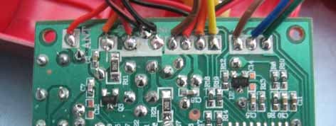
Q6N199ELA
Jun 07, 2007RC Pterosaur (Transmitter)
Equipment Class
DXX - Part 15 Low Power Communication Device TransmitterQ6N205ELA
May 22, 2007Tiger Cub
Equipment Class
DXX - Part 15 Low Power Communication Device Transmitter