Q6QTELIMAX21XVOIP GATEWAY
HS Teliann, Inc.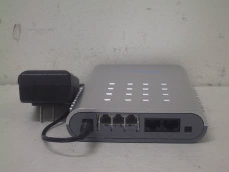
Click to zoom
Application Details
- Equipment Class
- JBP - Part 15 Class B Computing Device Peripheral
- Date of Grant
- Jul 15, 2003
- Application Purpose
- Original Equipment
- Date of Application
- Jul 15, 2003
- Equipment Note
- VOIP GATEWAY
- Company
- HS Teliann, Inc.
- Country
- South Korea
Documents & Files
Document Text
Text extracted from the exhibit documents filed with the FCC. Open a document above to read the original.
Users Manual
Report No: BWS-03-EF-0028 FCC ID : Q6QTELIMAX21X Date of Test : JUNE 17,2003 HS Teliann, Inc. VOIP Gateway Telimax 21x Appendix 6. User Manual Refer to the following pages Telⓘmax 211/212 User’s Manual VER 1.1.7.0 HS Teliann Inc. Telimax 211/212 User’s Manual ¾ Before using This user’s manual includes information concerning the components, installation and usage of Telⓘmax211/212. Please read this manual and use caution before installing Telⓘmax211/212 equipment. In the case of questions or comments regarding equipment, contact us at the number provided on the product warrantee. ¾ Safety precautions Because Tel○ i max211/212 comes with various drivers and software installed, there is no need for card installation or other tasks before using. HS Teliann accepts no responsibility for problems attributable to the mishandling of equipment by any technician that is not certified by HS Teliann or by the user himself. Therefore, in the case that the customer desires to upgrade the present system functions or repair malfunctioning units, contact the location of purchase and a certified expert. 2 Telimax 211/212 User’s Manual Table of Contents Chapter 1 - Summary 4 1.1 About Telimax211/212 4 1.2 Telimax211/212 components and functions 5 1.2.1 Connection module 5 1.2.2 Maintenance module 5 1.2.3 VoIP module 6 1.2.4 LED names and functions 7 1.2.5 Rear face 8 Chapter 2 – Inspection before installation 9 2.1 Power requirements 9 2.2 Working environment 9 2.3 Confirming the parts of Telimax211/212 9 Chapter 3 – Installation 10 3.1 Cable connection 10 3.2 PC network configuration for Web Server connection 11 3.3 Connecting to the Web Server 13 3.4 Network configuration 15 3.4.1 Information 16 3.4.2 Configuration 18 3.4.3 Command 28 Chapter 4 – PC configuration 32 Chapter 5 – Placing a call 34 5.1 Placing a call using the VoIP mode 34 5.2 Placing/receiving calls using the PSTN mode 34 5.2.1 Placing a call with the power in the ON state 34 5.2.2 Receiving a call with the power in the ON state 34 5.2.3 Placing/receiving a call with the power in the OFF state 35 Product quality warrantee 36 3 Telimax 211/212 User’s Manual Chapter 1 - Summary 1.1 About Telⓘmax211/212 Telⓘmax211/212 is a 1/2 channel VoIP(Voice over Internet Protocol) product which supports a standard protocol of H.323 as defined by the ITU-T for data telecommunication webs with an IP foundation. This product uses a data telecommunications web to support Ethernet for voice transfer, and offers voice calling by utilizing the standard protocol, H.323 (RAS, Q.931, H.245, RTP/RTCP). It also support the standard facsimile protocol, T.38을. It also allows the user to select between VoIP and PSTN Backup functions. Also, because standard protocols were used, it can be connected via existing data webs to equipment from other companies with convenient construction of both the internal and external webs of the VoIP. The menu has been systematically constructed for the user’s convenience and program modifications and configurations can be made from a remote location via the SNMP/Telnet/Web. 4 Telimax 211/212 User’s Manual Figure 1. Telⓘmax211/212 Service web 1.2 Telⓘmax211/212 components and functions 1.2.1 Connection module - 10 BASE –T Ethernet interface - RING DETECTION & RING GENERATION - GAIN control function - Analog 1/2 port Interface (RJ11) 1.2.2 Maintenance module - Monitoring and setting functions via RS232 telecommunications - Remote program download - Management from a remote location using SNMP/Telnet/Web 5 Telimax 211/212 User’s Manual 1.2.3 VoIP module - G.711 (A_law, U_law), G.723.1, G.729 Coding type support - Echo Cancellation - ITU-T의 H.323 standard protocol support - RAS, Q.931, H.245, RTP/RTCP support - Compatibility with various equipment 6 Telimax 211/212 User’s Manual 1.2.4 LED names and functions The following is a figure of the LED on the front face of Telⓘmax211/212 There is noTEL2 LED on Telⓘmax211 Figure 2. Telⓘmax211/212 Front face The following is a description of each function. Reset Loads the basic information PWR Lights on when power is supplied normally WAN Lights on when the connection between the WAN Port and Ethernet is normal PC Lights on when the Ethernet connected to the PC or HUB is normal LINE Lights on when using PSTN TEL1 Lights on when using Teliphone line 1 TEL2 Lights on when using Teliphone line 2 7 Telimax 211/212 User’s Manual 1.2.5 Rear Face The following is a figure of the connectors on the rear face of Telⓘmax211/212 There are no connectors on Telⓘmax211 Figure 3. Telⓘmax211/212 Rear Face The following is a description of each connector. PWR Cable connection to the power-supplying adapter (DC 5V) TEL1 Connection to the telephone line TEL2 Connection to the telephone line(Does not exist on Telⓘmax201 LINE Connection to the PSTN Line WAN Connection to the Ethernet Port via the Ethernet cable (1:1 connector) of the HUB or router with the external connection (cable modem or ADSL). PC Connection to the Ethernet Port via the Ethernet cable (1:1 connector) of the PC or HUB. CONSOL Connection to the Serial cable (to be used only by system managers) 8
Users Manual
Telimax 211/212 User’s Manual Chapter 2 – Inspection before installation 2.1 Power requirements 1) AC voltage : external power adapter, 110V~220V, 60Hz 2) Use only the power adapter supplied with the product. 3) For procurement of additional adapters, contact the supplier directly. Telⓘmax211/212 shows maximal performance when using a power with minimal sparks and noise. Different power control devices may be used out of necessity. Also, because liquids or metallic substances can result in electric shock, short circuit, or fire when allowed to pass into the equipment, do not indiscriminately repair or modify the product. 2.2 Working environment 1) Temperature : 0~40 °C 2) Humidity : 5% ~ 85% 2.3 Confirming the parts of Telⓘmax211/212 Open the packaging of Telⓘmax211/212 to confirm the inclusion of the following. ○ 1 1 Telⓘmax211/212 main component ○ 2 1 power supply adapter ○ 3. 1 Ethernet cable (1:1 connector) ○ 4 Telephone wire: Telⓘmax211(1), Telⓘmax212(2) ⑤ User’s manual, part 1 9 Telimax 211/212 User’s Manual Chapter 3 - Installation 3.1 Cable connection 1) Connect the WAN Port of Telⓘmax211/212 to the router connected to the external network or the Ethernet Port (ADSL, cable modem, etc) of the modem via the Ethernet cable. 2) Connect the PC Port of Telⓘmax211/212 to the LAN Card of the PC or the Ethernet Port of the HUB (connect using the Ethernet cable when using a PC) 3) Connect the telephone lines to be used with Telⓘmax211/212 to TEL1 and TEL2 Ports. 4) Turn on the power after the above cable connections have been made. Figure 4. Cable connection ¾ Checking basic functions 1) If the PWR, WAN, PC LED light up with a green color after the above connections have been made and the power turned on, this means that the product is functioning normally. 2) If the TEL1, TEL2 LED light up with a green color upon picking up the telephone receiver connected to the respective ports, this means that the 10 Telimax 211/212 User’s Manual product is functioning normally. 3) If the above equipment is not functioning normally, check the respective connectors. 3.2 PC network configuration for Web Server connection This product can connect to the existing Web Server and easily set the parameters. Proceed in the following order. In order to connect to the Web Server address internalized within the equipment, http://192.168.125.1:8763, set up the PC network configuration as the same network group as the Web Server. 3.2.1 Setting up with WINDOWS 9X, ME 1) [Start]->[Configuration]->[Control panel]->[Network] double click -> [TCP/IP] double click. 2) Enter the IP address and subnet mask as appear below when the TCP/IP information appears. 3) Enter an IP address between 192.168.125.2 and 192.168.125.254, and the subnet mask as 255.255.255.0. ☞ Caution : In the case that several PCs are connected be careful not to use the same IP address twice. 4) After selecting the Gateway tab, click the [Add] button after entering the new Gateway, 192.168.125.1. 5) After completing this process, a screen asks if you wish to reboot. In order to apply the modified network configuration, click the Yes (Y) button and reboot the system. 11 Telimax 211/212 User’s Manual 3.2.2 Setting up with WINDOWS 2000 [Start]->[Configuration]->[Control Panel]->[Network] double click -> [Network and telephone connections] double click -> [local network connection] click on the icon with the right side of the mouse and select registration information. Double click [TCP/IP] at local network connection registration information. 12 Telimax 211/212 User’s Manual Enter the IP address and subnet mask after the TCP/IP information appears as below. Enter the IP address between 192.168.125.2 and 192.168.125.254, and a subnet mask of 255.255.255.0. Also, enter the Gateway address as 192.168.125.1. ☞ Caution : In the case that several PCs are connected be careful not to use the same IP address twice. After completing the above process, click on [Confirm] and click on [Confirm] at “local network registration information”. (There is no need to reboot Windows2000) 3.3 Connecting to the Web Server 1) After completing the PC network configuration, set up the Web browser (Internet Explorer or Netscape) and after entering the Web Server address, http://192.168.125.1:8763 press enter. At the time of shipment, the IP Port address of the LAN port of to be connected to the PC is set at 192.168.125.1 and represents the Web Server address. Thus according, in the case of IP address modification, one must use the new address in order to connect to the Web Server. 13 Telimax 211/212 User’s Manual 2) If the product is functioning properly, the following screen will appear. After entering the USER ID, PASSWORD, and LANGUAGE click the button. At the time of shipment, the ID and Password are registered according the user. The Password can be changed in the password modification menu. 3) 14 Telimax 211/212 User’s Manual 4) After completion of the Login process, the following system information page will appear. ☞ In order to place/receive telephone calls, the network and telephone setting must be properly set at the above menu. 3.4 Network configuration The Web Server is divided into Information, Configuration, and Command and each of these sections must be properly set to ensure normal product function. Before setting up the menu, the user must accurately know the state of the present web (Static, DHCP, ADSL/PPPoE) and the corresponding necessary information (IP address, Subnet Mask, Gateway address, H.323 ID, E.164 ID). 15 Telimax 211/212 User’s Manual 3.4.1 Information 1. System information - Model type : model type of the product - Firmware version : version of the presently running software - Firmware release date : the manufacture date of the respective software - Network type : type of the presently connected network - System IP : the product’s IP Address - Network status : connection status to the network - H.323 mode : VoiP call connection type (Gatekeeper / Dire…
Text truncated - open the document above for the full version.
Users Manual
Telimax 211/212 User’s Manual Chapter 4 – PC Configuration The network configuration of the PC to be used must be changed as follows. - At the Windows Background screen click on [Start]->[Configuration]- >[Control panel]. Click on the network icon that appears on the screen. - Select TCP/IP from the network configuration components and click on [registration information]. - The <TCP/IP registration information> page will appear. - Select <Automatically receive an IP address> and click on the [Confirm] button and reboot the system.. 1) Set up for WINDOWS 9X, ME - [Start]->[Configuration]->[Control Panel]-> Double click [Network] -> Double click [TCP/IP]. - When the TCP/IP registration information screen appears, select “automatic selection of the IP address”. - Select “DNS not to be used” from the DNS component list. - After completing the above process, click yes[Y] at the screen asking whether to reboot the system in order to save and apply the changed network information. After completing the PC and product configuration processes, Internet usage is possible. 2) Set up for INDOWS 2000 [Start]->[Configuration]->[Control panel]->Double click [Network] -> Double click [Network and telephone connection] -> Click on [local network connection] with the right side button on the mouse and click on registration information -> Double click [TCP/IP] 32 Telimax 211/212 User’s Manual When the Internet protocol (TCP/IP) registration information screen appears, select “automatically receive the IP address” and “automatically receive the DNS server address”. 33 Telimax 211/212 User’s Manual After completing the above entries, select “Confirm”. Select “Confirm” again at the “local network registration information” screen opened earlier (There is no need to reboot the system with WINDOWS 2000). After completing the PC and product configuration processes, Internet usage is possible. Chapter 5 – Placing a call 5.1 Placing a call in the VoIP mode Follow the procedure below in order to place a call. 1) Pick up the receiver connected to the equipment. 2) Enter the number of the party to be called. 3) Press the # button. (In the case that the # button is not pressed, the call is placed after 4 seconds) 4) A dial tone will be heard in normal cases. Ex) If the number of the party to be called is 123456, in sequence, press 123456#. 5.2 Placing and receiving calls in the PSTN mode Placing a call in the PSTN mode uses a normal PSTN line and not the VoIP line to make calls. The user can press the “#” button to call in the PSTN mode. Also, in the case that there is a problem with the network or power shortage of other equipment, the product automatically switches to the PSTN mode. 5.2.1 Placing a call in the power ON state Follow the procedure below.. 1) Pick up the receiver connected to the product. 2) Press the # button to hear a dial tone. 3) Enter the number of the party to be called. In the case of Telⓘmax212, if the PSTN line is being used by another line, a busy signal will be heard. 5.2.2 Receiving calls in the power ON state If a call from a number on the PSTN Line is received from the exterior, the telephone connected to TEL1 will ring. In the case of Telⓘmax212 the telephone connected to 34 Telimax 211/212 User’s Manual TEL2 will ring if TEL1 is being used. 5.2.3 Placing and receiving calls in the power OFF state If the product’s power is in the OFF state, calls are automatically dealt with in the PSTN mode. One places and receives calls as one would with a normal telephone. Once the power is turned on, the product will automatically switch to VoIP mode. 35 Telimax 211/212 User’s Manual Product Warrantee z We wish to thank you for purchasing our product. We are doing all we can to ensure product quality, but in the case of malfunction, we urge you to receive the necessary service. Product name Telimax 212 Product number Purchase date year month day Purchase location z Contents of warrantee 1) Free after service can be received for product malfunction for one year from the purchase date (duration of quality guarantee). 2) The following correspond to charged service z Malfunction attributable to customer mishandling z Malfunction due to natural disaster (fire, earthquake, flood, lightning etc.) z Malfunction due to problem in used power source. z Malfunction due to problematic adaptor. z Malfunction arising from non-certified service staff attempting to repair or clean product 36
Block Diagram
Report No: BWS-03-EF-0028 FCC ID : Q6QTELIMAX21X Date of Test : JUNE 17,2003 HS Teliann, Inc. VOIP Gateway Telimax 21x Appendix 5. Block Diagram Refer to the following pages 5 5 4 4 3 3 2 2 1 1 DD CC BB AA RS232 ETHERNET MOTORORA MPC850 A D DSP_nCS I2C_DATA I2C_CLK nRESET UART_RxD,UART_TxD, UART_DCD,UART_RTS,UART_CTS RX0D[0..3] RX1D[0..3] TX0D[0..3] TX1D[0..3] COL0,CRS0,TCLK0,RCLK0, TXEN0,TXER0,RXDV0,RXER0 COL1,CRS1,TCLK1,RCLK1, TXEN1,TXER1,RXDV1,RXER1 MHZ_25ENET 4MHZCPU_CLK nRESET_OUT JTAG RJ-45 CH0 RJ-45 CH1 RJ11_Console D nRESET A FLASH DSP_A DSP_D SDRAM_nCS, SDRAM_CLK,SDRAM_CKE,nBE[0..3] Power Regulation nOE,R/W,nCS0,nCS1,nRESET_OUT DSP DIGITAL_PWR D A[11..30] D[0..15] SDRAM A[18..29] D[0..15] D[0..7] A[28..31] SRAM A AD CS, OE, WE, CLK A[0..15]D[0..1 5] CS, OE, WE 25MHZ PCM, CONTROL SIGNAL PCM, CONTROL SIGNALSLIC1 SLIC0 RJ-11 CH1 RJ-11 CH0 PSTN CON Telimax 21x BLOCK DIAGRAM PSTN CONTROL 16.3284MHZ DSP_R/W LED 1X6 TEL1,TEL2,PSTN WAN , PC BLOCK DIAGRAM 1.2 Telimax 21x A3 2020Saturday, June 14, 2003 Title SizeDocument NumberRev Date:Sheetof
External Photos
Report No: BWS-03-EF-0028 FCC ID : Q6QTELIMAX21X Date of Test : JUNE 17,2003 HS Teliann, Inc. VOIP Gateway Telimax 21x Appendix 3. External Photographs
ID Label/Location Info
Report No: BWS-03-EF-0028 FCC ID : Q6QTELIMAX21X Date of Test : JUNE 17,2003 HS Teliann, Inc. VOIP Gateway Telimax 21x Appendix 2. FCC ID Label and location Product Label Sample with FCC ID Label information Following is a sample copy of the label that will be placed on the rear cabinet of the product. The FCC identifier is marked in the product label. The warning statement is described in the user manual. Label Location The label shown above shall be permanently affixed at a bottom side of the device and be readily visible to the user at the time purchase.(Labeling requirements per 2.925) HS Teliann, Inc. VOIP Gateway Model : Telimax 21x FCC ID : Q6QTELIMAX21X This device complies with Part 15 of the FCC Rules. Operation is subject to the following two conditions: (1) this device may not cause harmful interference, and (2) this device must accept any interference received, including interference that may cause undesired operation.
Internal Photos
Report No: BWS-03-EF-0028 FCC ID : Q6QTELIMAX21X Date of Test : JUNE 17,2003 HS Teliann, Inc. VOIP Gateway Telimax 21x Appendix 4. Internal Photographs of EUT Report No: BWS-03-EF-0028 FCC ID : Q6QTELIMAX21X Date of Test : JUNE 17,2003 HS Teliann, Inc. VOIP Gateway Telimax 21x
Operational Description
About Telⓘmax211/212 Telⓘmax211/212 is a 1/2 channel VoIP(Voice over Internet Protocol) product which supports a standard protocol of H.323 as defined by the ITU-T for data telecommunication webs with an IP foundation. This product uses a data telecommunications web to support Ethernet for voice transfer, and offers voice calling by utilizing the standard protocol, H.323 (RAS, Q.931, H.245, RTP/RTCP). It also support the standard facsimile protocol, T.38을. It also allows the user to select between VoIP and PSTN Backup functions. Also, because standard protocols were used, it can be connected via existing data webs to equipment from other companies with convenient construction of both the internal and external webs of the VoIP. The menu has been systematically constructed for the user’s convenience and program modifications and configurations can be made from a remote location via the SNMP/Telnet/Web.
Test Report
This report only responds to the tested sample and may not be reproduced, except in full, without written approval of the BWS TECH,Inc. Electromagnetic Emission FCC MEASUREMENT REPORT VERIFICATION OF COMPLIANCE FCC PART15 CERTIFICATION PRODUCT : VOIP GATEWAY MODEL/TYPE NO : Telimax 21x FCC ID : Q6QTELIMAX21X TRADE NAME : HS Teliann, Inc. APPLICANT : HS Teliann, Inc. 195-1, Neungpyung-Ri, Opo-Eub, Kwangju-Si, Kyonggi-Do, 464-890 Korea FCC CLASSIFICATION : JBP : Part 15 Class B Computing Device Peripheral FCC RULE PART(S) : FCC Part 15 Subpart B FCC PROCEDURE : Certification DATES OF TEST : June 17, 2003 DATES OF ISSUE : June 23, 2003 TEST REPORT No. : BWS-03-EF-0028 TEST LAB. BWS Tech., Inc. (Registration No. : 553281) This VOIP GATEWAY Telimax21x has been tested in accordance with the measurement procedures specified in ANSI C63.4-2000 at the BWS TECH/EMC Test Laboratory and has been shown to be complied with the electromagnetic emission limits specified in FCC Rule Part15 Subpart B Section15.107 and 15.109 I attest to the accuracy of data. All measurement herein were performed by me or were made under my supervision and are correct to the best of my knowledge and belief. I assume full responsibility for the completeness of these measurements and vouch for the qualifications of all persons taking them. The results of testing in this report apply to the product/system which was tested only. Other similar equipment will not necessarily produce the same results due to production tolerance and measurement uncertainties. K.Young Kim Chief of Laboratory Division BWS TECH Inc. BWS TECH Inc. www.bws.co.kr 294-9, Jungdae-Dong, Kwangju-Si, Kyunggi-Do, 464-080, Korea TEL: +82 31 762 0124 FAX: +82 31 762 0126 BWS TECH Inc. 2 of 16 294-9 Jungdae-Dong, Kwanggu-Si,Kyunggi-Do, 464-800, Korea Report No: BWS-03-EF-0028 FCC ID : Q6QTELIMAX21X Date of Test : JUNE 17,2003 HS Teliann, Inc. VOIP GATEWAY Telimax 21x TABLE OF CONTENTS Pages 1. General Information 3 2. Description of Test Facility 4 3. Product Information 5 4. Description of Tests 6~7 5. Test Condition 8~9 6. Test Results 10~1 4 7. Sample Calculation and Other Information 15 8. Test Equipment List 16 Appendix 1. Test Setup Photos Appendix 2. FCC ID Label and location Appendix 3. External Photos of EUT Appendix 4. Internal Photos of EUT Appendix 5. Block Diagram Appendix 6. User Manual BWS TECH Inc. 3 of 16 294-9 Jungdae-Dong, Kwanggu-Si,Kyunggi-Do, 464-800, Korea Report No: BWS-03-EF-0028 FCC ID : Q6QTELIMAX21X Date of Test : JUNE 17,2003 HS Teliann, Inc. VOIP GATEWAY Telimax 21x FCC TEST REPORT Scope – Measurement and determination of electromagnetic emission(EME) of radio frequency devices including intentional radiators and/or unintentional radiators for compliance with the technical rules and regulations of the U.S Federal Communications Commission(FCC) 1. General Information Applicant Manufacturer l EUT Type : VOIP GATEWAY l Model Number : Telimax 21x l FCC Identifier : Q6QTelimax 21x l S/N : Prototype l FCC Rule Part(s) : CFR Title 47 Part 15 Subpart B l Test Procedure : ANSI C63.4-2000 l FCC Classification : JBP : Part 15 Class B Computing Device Peripheral l Dates of Tests : June 17, 2003 l Place of Tests : BWS TECH Inc. EMC Testing Lab (FCC Registration Number : 553281) 294-9, Jungdae-Dong, Kwangju-Si, Kyunggi-Do, 464-080, Korea TEL: +82 31 762 0124 FAX: +82 31 762 0126 l Test Report No. : BWS-03-EF-0028 Company Name : HS Teliann, Inc. Company Address : 195-1, Neungpyung-Ri, Opo-Eub, Kwangju-Si, Kyonggi-Do, 464-890, Korea. Phone/Fax : Phone : +82 31 726 0110 Fax : +82 31 726 0030 Company Name : HS Teliann, Inc. Company Address : 195-1, Neungpyung-Ri, Opo-Eub, Kwangju-Si, Kyonggi-Do, 464-890, Korea. Phone/Fax : Phone : +82 31 726 0110 Fax : +82 31 726 0030 BWS TECH Inc. 4 of 16 294-9 Jungdae-Dong, Kwanggu-Si,Kyunggi-Do, 464-800, Korea Report No: BWS-03-EF-0028 FCC ID : Q6QTELIMAX21X Date of Test : JUNE 17,2003 HS Teliann, Inc. VOIP GATEWAY Telimax 21x 2. Description of Test Facility The measurement test for radiated and conducted emission test were conducted at the open area test site of BWS TECH Inc. facility located at 294-9, Jungdae-Dong, Kwangju-Si, Kyunggi-Do, Korea. The site is constructed in conformance with the requirements of the ANSI C63.4-2000 and CISPR Publication 16. The BWS TECH measurement facility has been filed to the Commission with the FCC for 3 and 10 meter site configurations. Detailed description of test facility was found to be in compliance with the requirements of Section 2.948 FCC Rules according to the ANSI C63.4-2000 and registered to the Federal Communications Commission(Registration Number : 553281 ). The measurement procedure described in American National Standard for Method of Measurement of Radio-Noise Emission from Low-Voltage Electrical and Electronic Equipment in the Range of 9kHz to 40GHz (ANSI C.63.4-2000) was used in determining radiated and conducted emissions from the HS Teliann, Inc. VOIP GATEWAY Model: Telimax 21x. BWS TECH Inc. 5 of 16 294-9 Jungdae-Dong, Kwanggu-Si,Kyunggi-Do, 464-800, Korea Report No: BWS-03-EF-0028 FCC ID : Q6QTELIMAX21X Date of Test : JUNE 17,2003 HS Teliann, Inc. VOIP GATEWAY Telimax 21x 3. Product Information 3.1 Equipment Description The Equipment Under Test(EUT) is the VOIP Gateway model : Telimax 21x(FCC ID : Q6QTELIMAX21X). This VOIP Gateway is powered by external AC/DC Adapter. Telimax21x is a 1/2 channel VoIP(Voice over Internet Protocol) product which supports a standard protocol of H.323 as defined by the ITU-T for data telecommunication webs with an IP foundation. This product uses a data telecommunications web to support Ethernet for voice transfer, and offers voice calling by utilizing the standard protocol, H.323 (RAS, Q.931, H.245, RTP/RTCP). It also support the standard facsimile protocol. It also allows the user to select between VoIP and PSTN Backup functions. 3.2 General Specification - Chassis Type : Plastics - Power Source : DC 5V AC/DC Adapter - Interf…
Text truncated - open the document above for the full version.
Test Setup Photos
Report No: BWS-03-EF-0028 FCC ID : Q6QTELIMAX21X Date of Test : JUNE 17,2003 HS Teliann, Inc. VOIP Gateway Telimax 21x Appendix 1. Test Setup Photographs Radiated Emission Test Setup
Contact Information
Applicant
Young Hur(Manager)
Test Firm
BWS TECH INCCheol-Ho Lee
Technical Specifications
| # | Rule Parts | Frequency Range | Power Output |
|---|---|---|---|
| 1 | 15B | - | - |
Other Applications from HS Teliann, Inc.
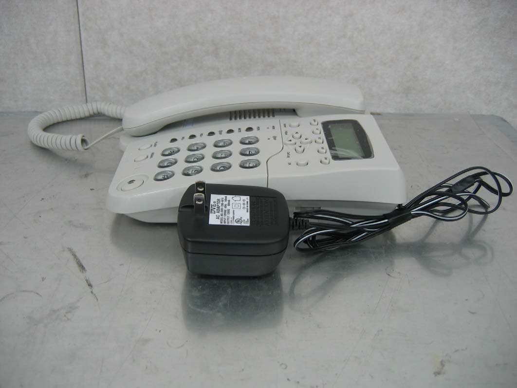
Q6QTP3200-D21
Dec 01, 2005IP Phone
Equipment Class
JBP - Part 15 Class B Computing Device Peripheral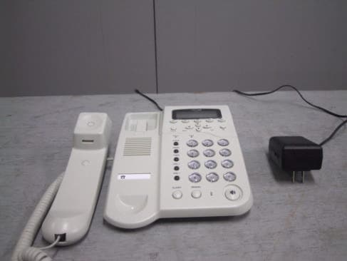
Q6QTELIPHONE3100
Jun 02, 2003Internet Phone
Equipment Class
JBP - Part 15 Class B Computing Device Peripheral