Q6ZHJ327TAlvita Wireless Activity Tracker
OMRON HEALTHCARE Co.,Ltd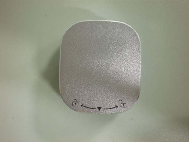
Click to zoom
Application Details
- Equipment Class
- DTS - Digital Transmission System
- Date of Grant
- Dec 04, 2014
- Application Purpose
- Original Equipment
- Date of Application
- Dec 04, 2014
- Equipment Note
- Alvita Wireless Activity Tracker
- Frequency Range
- 2402.00000000 - 2480.00000000
- Company
- OMRON HEALTHCARE Co.,Ltd
- Country
- Japan
Documents & Files
Document Text
Text extracted from the exhibit documents filed with the FCC. Open a document above to read the original.
Users Manual
HJ-327T-ZG _ A _ M13 _140220.pdf INSTRUCTION MANUAL HJ-327T H J-327T-ZG 9527561-8A Alvita Wireless Activity Tracker CONTeNTSBefORe USINgINSTRUCTIONSMAINTeNANCeCONTeNTSCONTeNTS CONTeNTS Before Using INTRODUCTION ............................................1 IMPORTANT SAFETY INFORMATION .....2 K NOW YOU R TR ACK ER ..............................4 INSERTING THE BATTERY .........................5 CHANGING THE BATTERY COVER ..........6 OPTIONAL STRIDE LENGTH MEASUREMENT ...........................................7 PAIRING THE TRACKER WITH SMARTPHONE ...............................................8 Instructions USING THE TRACKER ...............................10 TRANSFERRING AND DELETING DATA ...14 Maintenance MAINTENANCE AND STORAGE .............16 BATTERY REPLACEMENT ........................18 TROUBLESHOOTING .................................20 SPECIFICATIONS .........................................24 FCC STATEMENT ........................................26 LIMITED WARRANTY ...............................28 DATA TRANSMISSION AND TRADEMARKS ............................................30 1 MAINTeNANCeCONTeNTSBefORe USINgINSTRUCTIONSMAINTeNANCeCONTeNTSBefORe USINgINSTRUCTIONS INTRODUCTION Thank you for purchasing the OMRON Alvita Wireless Activity Tracker (HJ-327T). Activity Tracker Battery (CR2032) Clip Spare battery cover Coin shaped screwdriver Quick Start Guide This Tracker features advanced 3D Smart Sensor technology - so it knows exactly when you’re taking a step. You can easily track your progress by transferring your walking data from the Tracker to your smartphone. Use this tracker everyday to monitor your fitness achievements! Your Tracker comes with the following components: Please read this instruction manual thoroughly before using the tracker. Before Using 2 CONTeNTSBefORe USINgINSTRUCTIONSMAINTeNANCeBefORe USINgCONTeNTS IMPORTANT SAfeTY INfORMATION Warning: Improper use may result in death or se r iou s i nju r y. y Contact your doctor or healthcare provider before beginning a weight reduction or exercise program. y Keep the tracker out of the reach of young children. The tracker contains small pieces that may be swallowed. Immediately contact your physician if any piece is swallowed. y If battery fluid gets in your eyes, on your skin or clothing immediately rinse with plenty of clean water. Contact a physician immediately. y Do not put the tracker near (within 9 inch) implantable medical tracker such as pacemakers. y In places where radio communications are prohibited, remove the tracker’s battery to turn off the Bluetooth ® . go to next page 3 MAINTeNANCeCONTeNTSBefORe USINgINSTRUCTIONSMAINTeNANCeCONTeNTSBefORe USINgINSTRUCTIONS Caution: Improper use may result in minor or moderate injury to the user or damage to the equipment. y Do not throw the battery into fire. The battery may explode. y Always use the type of battery indicated. y Do not immerse the tracker or any of the components in water. The tracker is not waterproof. y Do not disassemble or modify the tracker. y Remove the battery from this tracker if you are not going to use it for a long period of time (approximately three months or longer). y Do not subject the tracker to strong shock such as dropping it on the ground. y Do not put the tracker in the back pocket of your pants or skirt. y Dispose of the tracker, battery, and components according to applicable local regulations. Unlawful disposal may cause environmental pollution. y Do not place the tracker in direct contact with your skin if you have sensitive skin or the area where you place the tracker has numbness, swelling, eczema, skin irritation, a broken bone or an injury. 4 CONTeNTSBefORe USINgINSTRUCTIONSMAINTeNANCeBefORe USINgCONTeNTS KNOW YOUR TRACKeR Main Tracker FrontBack Display (touch screen) Clip Display Data transfer indicator Measurement results transfer indicator Low battery indicator Exhausted battery indicator Spare Battery Cover Coin shaped screwdriver 5 MAINTeNANCeCONTeNTSBefORe USINgINSTRUCTIONSMAINTeNANCeCONTeNTSBefORe USINgINSTRUCTIONS INSeRTINg THe BATTeRY 1. Remove the battery cover from the tracker. (1) Rotate the battery cover counter-clockwise. (2) Lift the battery cover out of the tracker. 2. Insert the battery (CR2032) with the positive side (+) face up. Caution: Do not insert the battery with the polarities in the wrong direction. 3. Replace the battery cover. (1) Align two ▼ marks and press the battery cover down. (2) Rotate the cover clockwise. When is displayed the tracker’s screen, proceed to “PAIRING THE TRACKER WITH SM A RT PHON E”. 6 CONTeNTSBefORe USINgINSTRUCTIONSMAINTeNANCeBefORe USINgCONTeNTS CHANgIN g THe BATTeRY COVeR A battery cover with clip is attached to the tracker at the time of purchase. You can replace it with the spare battery cover depending on your needs. Attach to the trackerRemove from the tracker 1. Align the protrusion on the battery cover with the indent on the tracker. 2. Insert the coin shaped screwdriver into the groove of the battery cover. 3. Rotate the battery cover clockwise. 1. Insert the coin shaped screwdriver into the groove of the battery cover. 2. Rotate the battery cover counter- clockwise. 3. Lift the battery cover out of the t racker. 7 MAINTeNANCeCONTeNTSBefORe USINgINSTRUCTIONSMAINTeNANCeCONTeNTSBefORe USINgINSTRUCTIONS OPTIONAL STRIDe LeNgTH M eA SUR eMeNT The initial stride length displayed on the app is an estimated value calculated by your height setting. You may choose to adjust your stride length by adding the new value in the app. For instructions on calculating your stride manually, please refer to the following instruction, and then entering the new value in the application. How to measure your stride length 1.Walk 10 steps with your normal stride as illustrated below. 2.Measure the distance from START to END in inches. 3. Calculate your stride length by dividing the total distance by 10. Example: Total distance = 320'' 320 ÷ 10 = 32 inches (2 feet 8 inches) Conversion Chart 12…
Text truncated - open the document above for the full version.
External Photos
External Photo Omron Healthcare HJ-327T External Photo Omron Healthcare HJ-327T External Photo Omron Healthcare HJ-327T
ID Label/Location Info
Label Design and Location Label Design and LocationLabel Design and LocationLabel Design and Location Designed For HJ-327T φ20mm Label All digits of FCC ID cannot be confirmed with singl e angle of sight, but all digits can be confirmed with various angles . ・ No battery is set when each user starts to use, so the user can confirm the FCC ID when a battery is s et. ・ FCC ID is also confirmed in User's manual. Battery contacts 1/1
Internal Photos
Internal Photo Omron Healthcare HJ-327T Antenna Internal Photo Omron Healthcare HJ-327T Internal Photo Omron Healthcare HJ-327T
RF Exposure Info
UL Japan, Inc. Ise EMC Lab 4383-326 Asama-cho, Ise-shi, Mie 516-0021 Japan T:: +81.596.24.8999 / F:: +81.596.24.8124 / W:: ul.com/jp November 21, 2014 UL Japan, Inc. 4383-326 Asama-cho, Ise-shi, Mie 516-0021 Japan FCC ID: Q6ZHJ327T To whom it may concern, We, UL Japan, Inc, hereby declare that Alvita Wireless Activity Tracker, model: HJ-327T (FCC ID: Q6ZHJ327T) of Omron Health care Co., Ltd. is exempt from RF exposure SAR evaluation as its output power meets the exclusion limits stated in KDB 447498D01(V05). KDB 447498D01(V05) has the following exclusion for portable devices: The 1g and 10g SAR test exclusion thresholds for 100 MHz to 6 GHz at test separation distances ≤ 50 mm are determined by: [(max. power of channel, including tune-up tolerance, mW)/(min. test separation distance, mm)] ·[√f(GHz)] ≤ 3.0 for 1-g SAR and ≤ 7.5 for 10-g extremity SAR, where •f(GHz) is the RF channel transmit frequency in GHz •Power and distance are rounded to the nearest mW and mm before calculation •The result is rounded to one decimal place for comparison The test exclusions are applicable only when the minimum test separation distance is ≤ 50 mm and for transmission frequencies between 100 MHz and 6 GHz. When the minimum test separation distance is < 5 mm, a distance of 5 mm is applied to determine SAR test exclusion. This device has f = 2.48 GHz and distance = 5 mm (minimum separation distance: 5mm was used in the calculation) and the maximum tune-up tolerance limit was 2 mW (converted from Output power in Theory of Operation value in dBm: 2dBm, and rounded off to the whole number). So for this device: 2 mW[maximum tune-up tolerance limit]/5 mm[minimum separation distance]*√2.48 = 0.6 *This is less than 3.0, so no SAR is required. Thank you for your attention to this matter. Takayuki Shimada Engineer of Ise EMC Lab. Consumer Technology Division UL Japan, Inc.
Test Report
Test report No. : 10553197H Page : 2 of 27 Issued date : November 21, 2014 FCC ID : Q6ZHJ327T UL Japan, Inc. Ise EMC Lab. 4383-326 Asama-cho, Ise-shi, Mie-ken 516-0021 JAPAN Telephone : +81 596 24 8999 Facsimile : +81 596 24 8124 REVISION HISTORY Original Test Report No.: 10553197H Revision Test report No. Date Page revised Contents - (Original) 10553197H November 21, 2014 - - Test report No. : 10553197H Page : 3 of 27 Issued date : November 21, 2014 FCC ID : Q6ZHJ327T UL Japan, Inc. Ise EMC Lab. 4383-326 Asama-cho, Ise-shi, Mie-ken 516-0021 JAPAN Telephone : +81 596 24 8999 Facsimile : +81 596 24 8124 CONTENTS PAGE SECTION 1: Customer information ......................................................................................................... 4 SECTION 2: Equipment under test (E.U.T.) ........................................................................................... 4 SECTION 3: Test specification, procedures & results ............................................................................ 5 SECTION 4: Operation of E.U.T. during testing .................................................................................... 8 SECTION 5: Radiated Spurious Emission .............................................................................................. 9 SECTION 6: Antenna Terminal Conducted Tests ................................................................................ 10 APPENDIX 1: Data of EMI test .............................................................................................................. 11 6dB Bandwidth ................................................................................................................................. 11 Maximum Peak Output Power .......................................................................................................... 13 Radiated Spurious Emission ............................................................................................................. 15 Conducted Spurious Emission .......................................................................................................... 19 Power Density ................................................................................................................................... 22 99%Occupied Bandwidth ................................................................................................................. 24 APPENDIX 2: Test instruments ............................................................................................................. 25 APPENDIX 3: Photographs of test setup ............................................................................................... 26 Radiated Spurious Emission ............................................................................................................. 26 Worst Case Position (Horizontal: X-axis/ Vertical:Y-axis) .............................................................. 27 Test report No. : 10553197H Page : 4 of 27 Issued date : November 21, 2014 FCC ID : Q6ZHJ327T UL Japan, Inc. Ise EMC Lab. 4383-326 Asama-cho, Ise-shi, Mie-ken 516-0021 JAPAN Telephone : +81 596 24 8999 Facsimile : +81 596 24 8124 SECTION 1: Customer information Company Name : Omron Healthcare Co., Ltd. Address : 53 Kunotsubo, Terado-cho, Muko, Kyoto 617-0002 Japan Telephone Number : +81-75-925-2279 Facsimile Number : +81-75-925-2046 Contact Person : Yoshinori Tsurumi SECTION 2: Equipment under test (E.U.T.) 2.1 Identification of E.U.T. Type of Equipment : Alvita Wireless Activity Tracker Model No. : HJ-327T Serial No. : Refer to Section 4, Clause 4.2 Rating : DC 3V (Coin battery: CR2032) Receipt Date of Sample : November 4, 2014 Country of Mass-production : China Condition of EUT : Production prototype (Not for Sale: This sample is equivalent to mass-produced items.) Modification of EUT : No Modification by the test lab 2.2 Product Description General Specification Clock frequency(ies) in the system : 32.768kHz, 32MHz Radio Specification Bluetooth (Low Energy) Radio Type : Transceiver Frequency of Operation : 2402-2480MHz Modulation : GFSK Bandwidth & Channel Spacing : 1MHz & 2MHz Power Supply (radio part input) : DC 2.5V Antenna type : Chip Antenna Antenna Gain : 5.05dBi Test report No. : 10553197H Page : 5 of 27 Issued date : November 21, 2014 FCC ID : Q6ZHJ327T UL Japan, Inc. Ise EMC Lab. 4383-326 Asama-cho, Ise-shi, Mie-ken 516-0021 JAPAN Telephone : +81 596 24 8999 Facsimile : +81 596 24 8124 SECTION 3: Test specification, procedures & results 3.1 Test Specification Test Specification : FCC Part 15 Subpart C: 2014, final revised on August 15, 2014 and effective October 14, 2014 Title : FCC 47CFR Part15 Radio Frequency Device Subpart C Intentional Radiators Section 15.207 Conducted limits Section 15.247 Operation within the bands 902-928MHz, 2400-2483.5MHz, and 5725-5850MHz 3.2 Procedures and results Item Test Procedure Specification Worst margin Results Remarks Conducted Emission FCC: ANSI C63.4:2003 7. AC powerline Conducted Emission measurements FCC: Section 15.207 N/A *1) N/A - IC: RSS-Gen 8.8 IC: RSS-Gen 8.8 6dB Bandwidth FCC: "Guidance for Performing Compliance Measurements on Digital Transmission Systems (DTS) Operating Under §15.247(issued on June 5, 2014)" FCC: Section 15.247(a)(2) See data. Complied Conducted IC: - IC: RSS-210 A8.2(a) Maximum Peak Output Power FCC: "Guidance for Performing Compliance Measurements on Digital Transmission Systems (DTS) Operating Under §15.247(issued on June 5, 2014)" FCC: Section 15.247(b)(3) Complied Conducted IC: RSS-Gen 6.12 IC: RSS-210 A8.4(4) Power Density FCC: "Guidance for Performing Compliance Measurements on Digital Transmission Systems (DTS) Operating Under §15.247(issued on June 5, 2014)" FCC: Section 15.247 (e) Complied Conducted IC: - IC: RSS-210 A8.2(b) Spurious Emission FCC: "Guidance for Performing Compliance Measurements on Digital Transmission Systems (DTS) Operating Under §15.247(issued on June 5, 2014)" FCC: Section15.2…
Text truncated - open the document above for the full version.
Test Setup Photos
Test report No. : 10553197H Page : 26 of 27 Issued date : November 21, 2014 FCC ID : Q6ZHJ327T UL Japan, Inc. Ise EMC Lab. 4383-326 Asama-cho, Ise-shi, Mie-ken 516-0021 JAPAN Telephone : +81 596 24 8999 Facsimile : +81 596 24 8124 APPENDIX 3: Photographs of test setup Radiated Spurious Emission Photo 1 Photo 2 Test report No. : 10553197H Page : 27 of 27 Issued date : November 21, 2014 FCC ID : Q6ZHJ327T UL Japan, Inc. Ise EMC Lab. 4383-326 Asama-cho, Ise-shi, Mie-ken 516-0021 JAPAN Telephone : +81 596 24 8999 Facsimile : +81 596 24 8124 Worst Case Position (Horizontal: X-axis/ Vertical:Y-axis) X-axis Y-axis Z-axis End of Report
Contact Information
Applicant
Yoshinori Tsurumi(CS Div. Regulatory Affairs Dept.)
Technical Contact
UL Japan, Inc.Takayuki Shimada
[email protected]81-596-24-8999
4383-326 Asama-cho, Ise-shi · Mie-ken · Japan
Test Firm
UL Japan, Inc. Head office EMC Lab.Tetsuya Hashimoto
Technical Specifications
| # | Rule Parts | Frequency Range | Power Output |
|---|---|---|---|
| 1 | 15C | 2.40 GHz - 2.48 GHz | 1.10 mW |
Other Applications from OMRON HEALTHCARE Co.,Ltd
Q6ZHEM7184T
Jun 02, 2026Blood Pressure Monitor
Equipment Class
DTS - Digital Transmission SystemQ6ZHBFH122T1
Apr 06, 2026Smart Scale
Equipment Class
DTS - Digital Transmission SystemQ6ZHEM7440T1
Mar 17, 2026Upper Arm Blood Pressure Monitor + ECG
Equipment Class
DTS - Digital Transmission System
Q6ZHEM7340TS
Aug 24, 2023Blood Pressure Monitor
Equipment Class
DTS - Digital Transmission System
Q6ZMHEM7145T2
Feb 05, 2022Blood Pressure Monitor
Equipment Class
DTS - Digital Transmission System