Q6ZHJA750CActivity Monitor
OMRON HEALTHCARE Co.,Ltd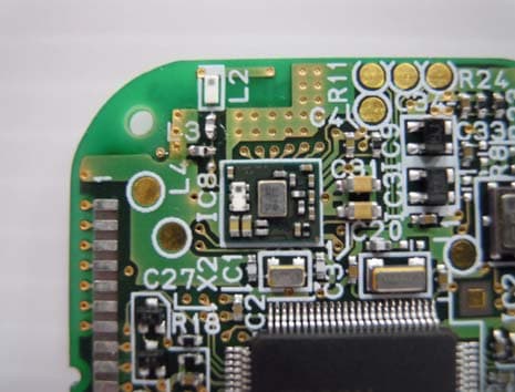
Click to zoom
Application Details
- Equipment Class
- DTS - Digital Transmission System
- Date of Grant
- Jul 31, 2014
- Application Purpose
- Original Equipment
- Date of Application
- Jul 31, 2014
- Equipment Note
- Activity Monitor
- Frequency Range
- 2402.00000000 - 2480.00000000
- Company
- OMRON HEALTHCARE Co.,Ltd
- Country
- Japan
Documents & Files
Document Text
Text extracted from the exhibit documents filed with the FCC. Open a document above to read the original.
Users Manual
Your OMRON HJA-750C Activity Monitor, excluding the battery, is warranted to be free from defects in materials and workmanship within 1 year from the date of purchase, when used in accordance with the instructions provided with the unit. The above warranties extend only to the original retail purchaser. We will, at our option, repair or replace without charge any monitor covered by the above warranties. Repair or replacement is our only responsibility and your only remedy under the above warranties. To obtain warranty service contact Omron’s Customer Support at 1-800-634- 4350. Information for warranty service is available on our website at www.omronhealthcare.com. Enclose the Proof of Purchase. Include a letter, with your name, address, phone number, and description of the specific problem. Pack the product carefully to prevent damage in transit. Because of possible loss in transit, we recommend insuring the product with return receipt requested. THE FOREGOING IS THE SOLE WARRANTY PROVIDED BY OMRON IN CONNECTION WITH THIS PRODUCT, AND OMRON HEREBY DISCLAIMS ANY OTHER WARRANTIES, EXPRESS OR IMPLIED, INCLUDING IMPLIED WARRANTIES OF MERCHANTABILITY AND FITNESS FOR A PARTICULAR PURPOSE. IMPLIED WARRANTIES AND OTHER TERMS THAT MAY BE IMPOSED BY LAW, IF ANY, ARE LIMITED IN DURATION TO THE PERIOD OF THE ABOVE EXPRESS WARRANTY. OMRON SHALL NOT BE LIABLE FOR LOSS OF USE OR ANY OTHER SPECIAL, INCIDENTAL, CONSEQUENTIAL OR INDIRECT COSTS, EXPENSES OR DAMAGES. This warranty provides you with specific legal rights, and you may have other rights that vary by jurisdiction. Because of special local requirements, some of the above limitations and exclusions may not apply to you. FOR CUSTOMER SERVICE Visit our web site at: www.omronhealthcare.com Call toll free: 1-800-634-4350 • In case this Product is used around the other wireless devices including microwave and wireless LAN, which operate same frequency band of this Product, there is a possibility that interference occurs between this Product and such other devices. If such interference occurs, please stop the operation of other devices or relocate this Product before using this Product or do not use this Product around the other wireless devices. • Due to the use of radio waves, third parties may intercept transmissions either deliberately or accidentally. Do not use this Product for matters related to vital secrets or human lives. • This Product is exclusively for Europe. Do not use this Product outside Europe. Doing so may conflict the radio law of the country. The Bluetooth ® word mark and logos are registered trademarks owned by Bluetooth SIG, Inc. and any use of such marks by OMRON HEALTHCARE Co., Ltd. is under license. Other trademarks and trade names are those of their respective owners. OMRON H EALTHCARE, I NC. 1925 West Field Court Lake Forest, I L 60045 U.S. A. www.omronhealthcare.com © 2014 OMRON HEALTHCARE, I NC. Made i n Japan PhenomenonCauseRectification Recorded data Number of recordable days 45 days mark blinks On the 37th day and after mark lights up On the 46th day and after Install the dedicated software on the personal computer. 1 Start the dedicated software. 2 Install the optional battery (CR2032 x 1) in the main unit before using it. In areas where the use of wireless equipment is prohibited, turn off the Bluetooth ® communication function of the main unit. 1 Open the battery cover and install the battery. 2 Attach the battery cover and tighten the screw. 3 Battery cover Communication area mark Strap attachment Battery cover screw Back of the main unitFront of unit Display select button An operation error has occurred. Error “Err” is displayed. The mark is blinking. INSTRUCTION MANUAL OMRON Activity Monitor HJA-750C 1. Main unit 2. Strap 3. Clip 4. Holder 5. Instruction Manual Remove the battery cover screw on the back of the main unit. You can transfer the device settings and recorded data from this product to your personal computer by using the dedicated software. * The optional “OMRON USB communication tray (HHX-IT4)” is required to transfer data. When the mark lights up or blinks, transfer the recorded data to the personal computer. When the recorded measurement data has been stored for over 36 days, the mark blinks. When it has been stored for over 45 days, the mark lights up. For details, consult the administrator. Battery power level is low. Use a commercially available mini screwdriver to remove the battery cover screw. Battery power is exhausted. Recorded measurement values have not been transferred after a certain period. is blinking. is lit up. The main unit has failed. Contact your Omron’s Customer Support ( See “11. LIMITED WARRANTY”) If your problem is not solved by taking the above actions, contact your Omron’s Customer Support. ( See “11. LIMITED WARRANTY”) NOTE: Note that all measurement values including the set values and the current data obtained on that day will be lost if a failure occurs or if your unit has to be repaired. We recommend that you transfer the measurement results as frequently as possible as a precautionary measure. Promptly replace it with a new battery (CR2032). ( “4. BATTERY INSTALLATION”) These specifications are subject to change without notice. OMRON Activity Monitor Active style Pro HJA-750C 3 VDC (Lithium battery CR2032 x 1) Up to 45 days (only today’s data is displayed) Approx.10 m *2 Temperature: -10 °C to +40 °C During data transfer: +5 °C to +35 °C Humidity: 30 to 85% RH Air pressure: 600 to 1050 hPa Accessories Weight METs, Steps Measurement function Memory Power voltage Product name *1. Construction type certification number is 007-AC0129. *2. The communication distance varies depending on the distance between communication devices, obstacles, radio wave conditions, and the states of devices used. Communication may be interrupted depending on the radio wave conditions. NFC-F (ISO/IEC 18092 compatible) Bluetooth ® Version 4.0 *1 (Low Energy support) Align the communication area ma…
Text truncated - open the document above for the full version.
External Photos
Photos製品写真■全体 ■寸法 単位: mm Overall Dimensions Unit: mm 40 52 12
ID Label/Location Info
■FCC ID Label Figure ※The label attached to the battery insert. For the optional battery can easily confirm the approval number to the user when the battery installed ■labeling position FCCID:Q6ZHJA750C FCC ID Label
Internal Photos
■PCB BLE Module Antenna
RF Exposure Info
UL Japan, Inc. Ise EMC Lab 4383-326 Asama-cho, Ise-shi, Mie 516-0021 Japan T:: +81.596.24.8999 / F:: +81.596.24.8124 / W:: ul.com/jp July 1, 2014 UL Japan, Inc. 4383-326 Asama-cho, Ise-shi, Mie 516-0021 Japan FCC ID: Q6ZHJA750C To whom it may concern, We, UL Japan, Inc, hereby declare that Activity Monitor, model: HJA-750C (FCC ID: Q6ZHJA750C) of OMRON HEALTHCARE Co., Ltd. is exempt from RF exposure SAR evaluation as its output power meets the exclusion limits stated in KDB 447498D01(V05). KDB 447498D01(V05) has the following exclusion for portable devices: The 1g and 10g SAR test exclusion thresholds for 100 MHz to 6 GHz at test separation distances ≤ 50 mm are determined by: [(max. power of channel, including tune-up tolerance, mW)/(min. test separation distance, mm)] ·[√f(GHz)] ≤ 3.0 for 1-g SAR and ≤ 7.5 for 10-g extremity SAR, where •f(GHz) is the RF channel transmit frequency in GHz •Power and distance are rounded to the nearest mW and mm before calculation •The result is rounded to one decimal place for comparison The test exclusions are applicable only when the minimum test separation distance is ≤ 50 mm and for transmission frequencies between 100 MHz and 6 GHz. When the minimum test separation distance is < 5 mm, a distance of 5 mm is applied to determine SAR test exclusion. This device has f = 2.48 GHz and distance = 5 mm (minimum separation distance: 5mm was used in the calculation) and the maximum tune-up tolerance limit was 1 mW. So for this device: 1 mW[maximum tune-up tolerance limit]/5 mm[minimum separation distance]*√2.48 = 0.3 *This is less than 3.0, so no SAR is required. Thank you for your attention to this matter. Takayuki Shimada Engineer of Ise EMC Lab. Consumer Technology Division UL Japan, Inc.
Test Report
Test report No. : 10377588H-A-R1 Page : 2 of 27 Issued date : July 1, 2014 Revised date : July 28, 2014 FCC ID : Q6ZHJA750C UL Japan, Inc. Ise EMC Lab. 4383-326 Asama-cho, Ise-shi, Mie-ken 516-0021 JAPAN Telephone : +81 596 24 8999 Facsimile : +81 596 24 8124 REVISION HISTORY Original Test Report No.: 10377588H-A Revision Test report No. Date Page revised Contents - (Original) 10377588H-A July 1, 2014 - - 1 10377588H-A-R1 July 28, 2014 P.6 Correction of FCC 15.31 (e) sentence 2 10377588H-A-R1 July 28, 2014 P.8 Addition and Correction of explanatory note for signal cable Test report No. : 10377588H-A-R1 Page : 3 of 27 Issued date : July 1, 2014 Revised date : July 28, 2014 FCC ID : Q6ZHJA750C UL Japan, Inc. Ise EMC Lab. 4383-326 Asama-cho, Ise-shi, Mie-ken 516-0021 JAPAN Telephone : +81 596 24 8999 Facsimile : +81 596 24 8124 CONTENTS PAGE SECTION 1: Customer information ......................................................................................................... 4 SECTION 2: Equipment under test (E.U.T.) ........................................................................................... 4 SECTION 3: Test specification, procedures & results ............................................................................ 5 SECTION 4: Operation of E.U.T. during testing .................................................................................... 8 SECTION 5: Radiated Spurious Emission .............................................................................................. 9 SECTION 6: Antenna Terminal Conducted Tests ................................................................................ 10 APPENDIX 1: Data of EMI test .............................................................................................................. 11 6dB Bandwidth ................................................................................................................................. 11 Maximum Peak Output Power .......................................................................................................... 13 Radiated Spurious Emission ............................................................................................................. 15 Conducted Spurious Emission .......................................................................................................... 19 Power Density ................................................................................................................................... 22 99%Occupied Bandwidth ................................................................................................................. 24 APPENDIX 2: Test instruments ............................................................................................................. 25 APPENDIX 3: Photographs of test setup ............................................................................................... 26 Radiated Spurious Emission ............................................................................................................. 26 Worst Case Position (Horizontal: Z-axis/ Vertical:Y-axis) .............................................................. 27 Test report No. : 10377588H-A-R1 Page : 4 of 27 Issued date : July 1, 2014 Revised date : July 28, 2014 FCC ID : Q6ZHJA750C UL Japan, Inc. Ise EMC Lab. 4383-326 Asama-cho, Ise-shi, Mie-ken 516-0021 JAPAN Telephone : +81 596 24 8999 Facsimile : +81 596 24 8124 SECTION 1: Customer information Company Name : OMRON HEALTHCARE Co., Ltd. Address : 53 Kunotsubo, Terado-cho, Muko, Kyoto 617-0002 Japan Telephone Number : +81-75-925-2045 Facsimile Number : +81-75-925-2046 Contact Person : Toshiaki Yuasa *Remarks: OMRON HEALTHCARE Co., Ltd. designates Hashimoto Electronic Industry as manufacturer of the product (Activity Monitor). SECTION 2: Equipment under test (E.U.T.) 2.1 Identification of E.U.T. Type of Equipment : Activity Monitor Model No. : HJA-750C Serial No. : Refer to Section 4, Clause 4.2 Rating : DC 3.0V Receipt Date of Sample : June 16, 2014 Country of Mass-production : Japan Condition of EUT : Production prototype (Not for Sale: This sample is equivalent to mass-produced items.) Modification of EUT : No Modification by the test lab 2.2 Product Description General Specification Clock frequency(ies) in the system : 32.768kHz, 2.7MHz, 32MHz Radio Specification Bluetooth (Low Energy) Radio Type : Transceiver Frequency of Operation : 2402-2480MHz Modulation : GFSK Bandwidth & Channel Spacing : 1MHz & 2MHz Power Supply (radio part input) : DC 2.5V Antenna type : λ/4 Monopole Antenna Antenna Gain : 2.5dBi Test report No. : 10377588H-A-R1 Page : 5 of 27 Issued date : July 1, 2014 Revised date : July 28, 2014 FCC ID : Q6ZHJA750C UL Japan, Inc. Ise EMC Lab. 4383-326 Asama-cho, Ise-shi, Mie-ken 516-0021 JAPAN Telephone : +81 596 24 8999 Facsimile : +81 596 24 8124 SECTION 3: Test specification, procedures & results 3.1 Test Specification Test Specification : FCC Part 15 Subpart C: 2014, final revised on May 1, 2014 and effective June 2, 2014 Title : FCC 47CFR Part15 Radio Frequency Device Subpart C Intentional Radiators Section 15.207 Conducted limits Section 15.247 Operation within the bands 902-928MHz, 2400-2483.5MHz, and 5725-5850MHz 3.2 Procedures and results Item Test Procedure Specification Worst margin Results Remarks Conducted Emission FCC: ANSI C63.4:2003 7. AC powerline Conducted Emission measurements FCC: Section 15.207 N/A N/A*1) - IC: RSS-Gen 7.2.4 IC: RSS-Gen 7.2.4 6dB Bandwidth FCC: "Guidance for Performing Compliance Measurements on Digital Transmission Systems (DTS) Operating Under §15.247(issued on April 9, 2013)" FCC: Section 15.247(a)(2) See data. CompliedConducted IC: RSS-Gen 4.6.2 IC: RSS-210 A8.2(a) Maximum Peak Output Power FCC: "Guidance for Performing Compliance Measurements on Digital Transmission Systems (DTS) Operating Under §15.247(issued on April 9, 2013)" FCC: Section 15.247(b)(3) CompliedConducted IC: RSS-Gen 4.8 IC: RSS-210 A8.4(4) Powe…
Text truncated - open the document above for the full version.
Test Setup Photos
Test report No. : 10377588H-A-R1 Page : 26 of 27 Issued date : July 1, 2014 Revised date : July 28, 2014 FCC ID : Q6ZHJA750C UL Japan, Inc. Ise EMC Lab. 4383-326 Asama-cho, Ise-shi, Mie-ken 516-0021 JAPAN Telephone : +81 596 24 8999 Facsimile : +81 596 24 8124 APPENDIX 3: Photographs of test setup Radiated Spurious Emission Photo 1 Photo 2 Test report No. : 10377588H-A-R1 Page : 27 of 27 Issued date : July 1, 2014 Revised date : July 28, 2014 FCC ID : Q6ZHJA750C UL Japan, Inc. Ise EMC Lab. 4383-326 Asama-cho, Ise-shi, Mie-ken 516-0021 JAPAN Telephone : +81 596 24 8999 Facsimile : +81 596 24 8124 Worst Case Position (Horizontal: Z-axis/ Vertical:Y-axis) X-axis Y-axis Z-axis End of Report
Contact Information
Applicant
Yoshinori Tsurumi(CS Div. Regulatory Affairs Dept.)
Technical Contact
UL Japan, Inc.Takayuki Shimada
[email protected]81-596-24-8999
4383-326 Asama-cho, Ise-shi · Mie-ken · Japan
Test Firm
UL Japan, Inc. Head office EMC Lab.Tetsuya Hashimoto
Technical Specifications
| # | Rule Parts | Frequency Range | Power Output |
|---|---|---|---|
| 1 | 15C | 2.40 GHz - 2.48 GHz | 1.20 mW |
Other Applications from OMRON HEALTHCARE Co.,Ltd
Q6ZHEM7184T
Jun 02, 2026Blood Pressure Monitor
Equipment Class
DTS - Digital Transmission SystemQ6ZHBFH122T1
Apr 06, 2026Smart Scale
Equipment Class
DTS - Digital Transmission SystemQ6ZHEM7440T1
Mar 17, 2026Upper Arm Blood Pressure Monitor + ECG
Equipment Class
DTS - Digital Transmission System
Q6ZHEM7340TS
Aug 24, 2023Blood Pressure Monitor
Equipment Class
DTS - Digital Transmission System
Q6ZMHEM7145T2
Feb 05, 2022Blood Pressure Monitor
Equipment Class
DTS - Digital Transmission System