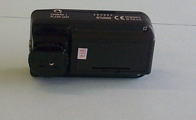
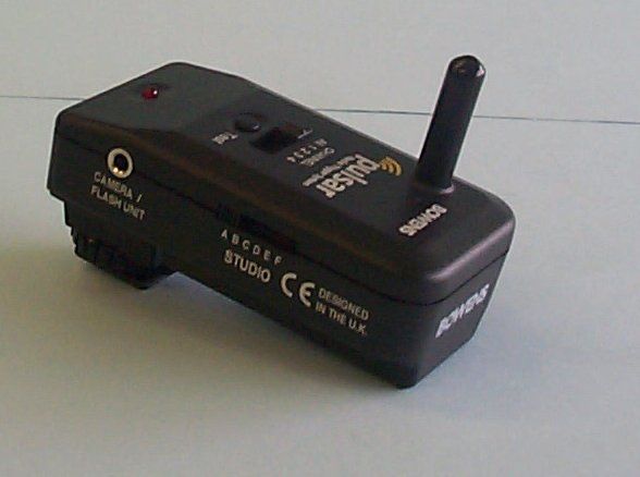
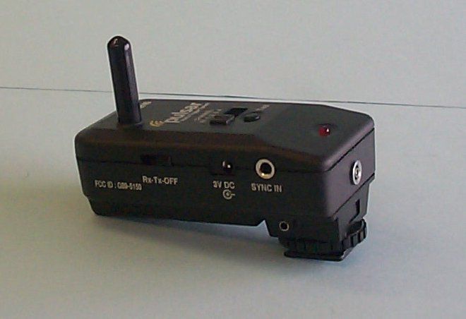
Q895150Photographic equipment radio trigger
Bowens International Limited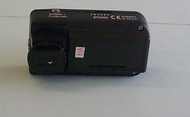
Click to zoom
Application Details
- Equipment Class
- DSR - Part 15 Remote Control/Security Device Transceiver
- Date of Grant
- Oct 05, 2003
- Application Purpose
- Original Equipment
- Date of Application
- Oct 05, 2003
- Equipment Note
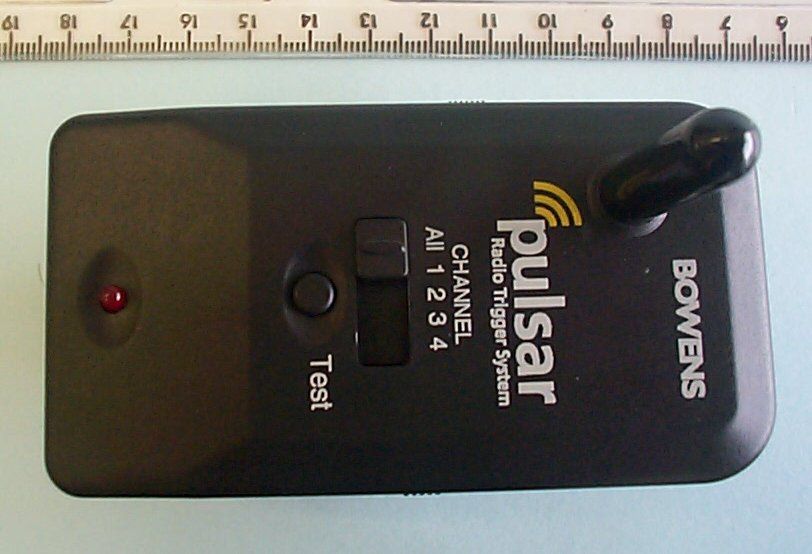
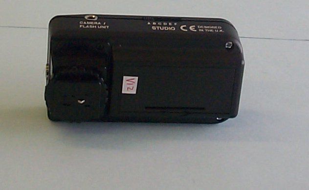
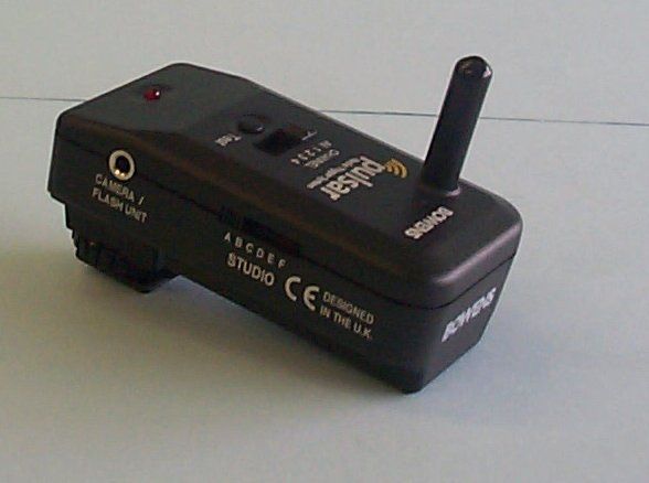
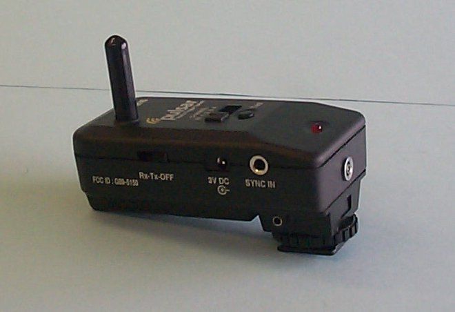
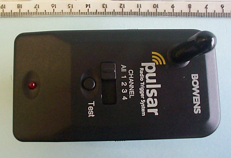
- Photographic equipment radio trigger
- Frequency Range
- 433.92000000 - 433.92000000
- Company
- Bowens International Limited
- Country
- United Kingdom
Documents & Files




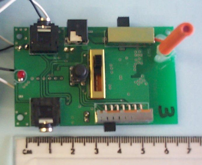
Document Text
Text extracted from the exhibit documents filed with the FCC. Open a document above to read the original.
Users Manual
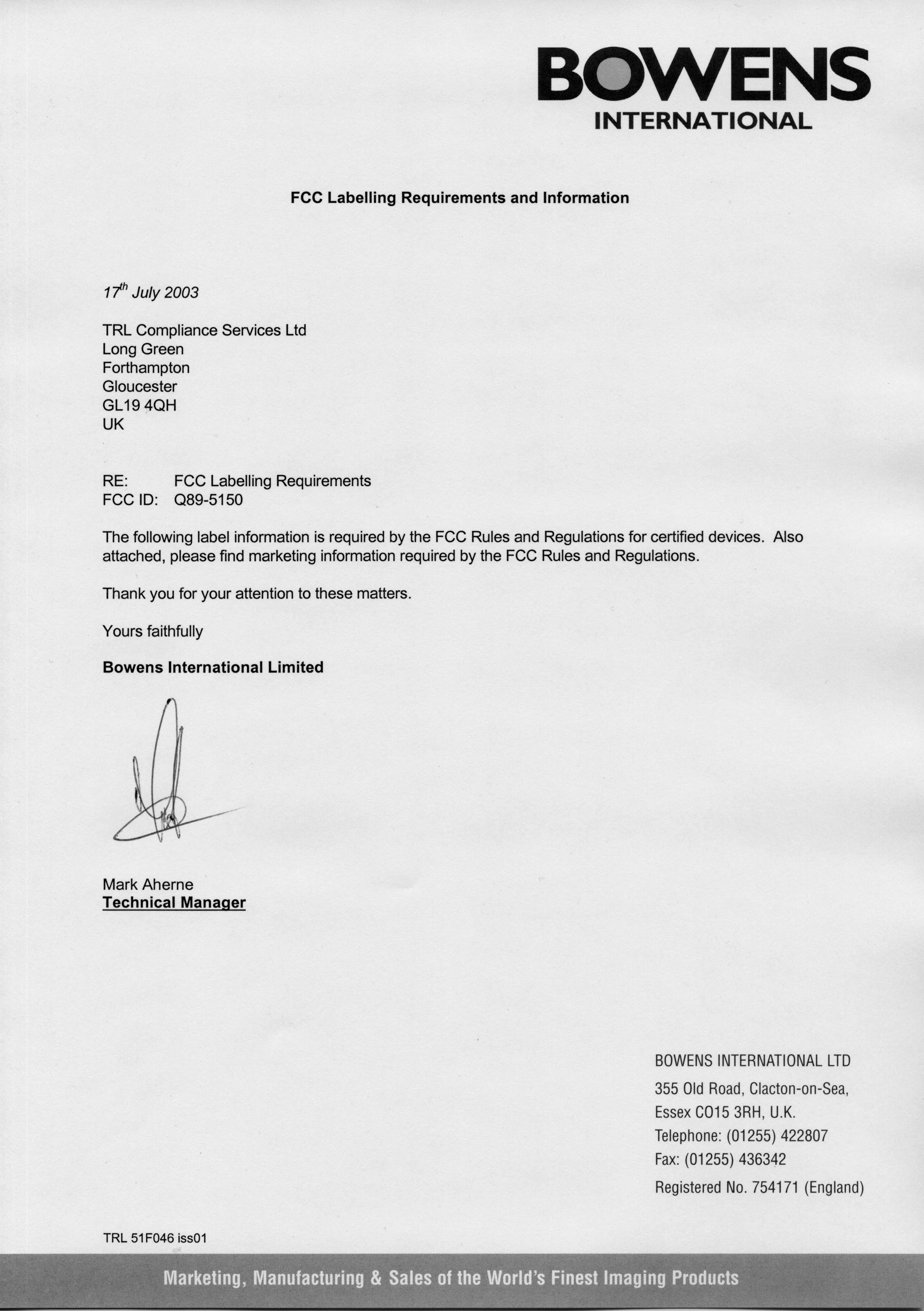
PULSAR RADIO TRIGGER INSTRUCTIONS BWL-0340/1 BOWENS INTERNATIONAL LIMITED 355 Old Road Clacton on Sea Essex CO15 3RH UK Tel:+44 (0)1255 422807 Fax:+44 (0)1255 436342 www.bowensinternational.com IMPORTANT MODIFICATIONS TO THE OPERATION OF THIS EQUIPMENT MAY VOID YOUR AUTHORITY TO USE THIS PRODUCT UNDER THE EQUIPMENT AUTHORISATION GRANTED BY THE REGULATING AGENCIES. Bowens International Limited Q89-5150 This device complies with Part 15 of the FCC Rules. Operation is subject to the following two conditions: (1) This device may not cause harmful interference, and (2) this device must accept any interference received including interference that may cause undesired operation. User Guide BOWENS Introduction Congratulations on choosing the Bowens PulsarRadio Trigger. Designed using the latest technology to produce a unit that is simple to operate,Pulsaris capable of triggering the widest range of photographic equipment including studio flash, cameras and light meters. Pulsarcan be used as either a Transmitter or Receiver allowing the ability to quickly change your lighting settings. You can easily substitute one Pulsarwith another by simply changing its mode or Channel settings. This is just one example of the versatility of Pulsar. In order to fully understand the many studio uses for your new Pulsar Radio Trigger, please take a moment to read through this user guide. Included in box: 1 x Instruction Manual 1 x Pulsar 2 x AAA Batteries 1 x Fixing Bracket 1 x Elastic Cord with Ends 4 x Rubber Feet 1 x Sync Cord 1 x Jack Plug Adapter Troubleshooting Try this first: Check the indicator on each unit is 'single flashing' indicating that the unit is ON and the battery is OK. Set both transmitter and receiver to studio ‘A’ and channel ‘All’ Turn all units OFF then back ON. Note: Units may not operate correctly if used in very close proximity to each other. Indicator on unit does not light when test button pressed. Try replacing batteries. Make sure power switch is set to either Transmit or Receive. Remove external power connector, to use internal batteries. Unit does not receive code. Set both transmitter and receiver channel select to All. Try using units in another area away from metal objects. Unit does not trigger device. Try the test button on the receiver to confirm electrical connection. Check cable connections. Try the alternative Sync output of the Pulsar. Unit is continually transmitting. Make sure test button is not obstructed. Try disconnecting external trigger sources. Check Battery condition. Turn PulsarOFF then back ON. In the unlikely event of a problem or fault with your Pulsarplease contact Bowens for additional help or to arrange a repair. 14www.bowensinternational.com3www.bowensinternational.com Operating Manual Contents DescriptionPage Introduction3 Channel Codes & Switches4 Power Requirements5 Mounting Bracket6 Mounting Pulsar7 Orientation8 Using Channels9 Metering Flash Settings10 Studio Operation11 Standard Connection12 Advanced Connection13 Troubleshooting14 Specifications15 Specifications Batteries 2 x AAA ,MN2400 or LR03 Battery Life Approx (Before low battery indication) Transmit Mode:Alkaline.... 560 Hours Nicad....... 350 Hours Receive Mode:Alkaline.... 224 Hours Nicad....... 140 Hours Typical Use:Alkaline.... 200 Hours Nicad....... 125 Hours Sync Voltage Out:3.3V max Size(L) 90mm x (W) 49mm x (H) 44mm (Typical dimensions including hot shoe) Weight122g (4.3 oz) Range100m (333 ft) Frequency 433 MHz (Europe & USA) ConformityFCC part 15 - CE Trigger Timings1/2000 500μS Delay Max Fixing MethodsCamera - PulsarHotshoe attachment. Other - Fixing adapter provided. AccessoriesPulsarExternal Power Supply. Motor drive Camera Sync-Cord. QUADX5V to 3V Adapter. For details contact your distributor. Due to our policy of constant product improvement Bowens International Limited reserve the right to change equipment specification without notice. 2www.bowensinternational.com 15www.bowensinternational.com Channel codes and Switches Sync-In and hot shoe Sync-In are internally connected. Sync-Out is designed for camera trigger although will also trigger flash. PC Sync-Out is used for flash trigger. Test Button Indicator Channel Select All-4 PC Sync Out (Flash Trigger) Sync Out (Camera / Flash Trigger) Mode Switch (TX, RX, Off) External Power In Sync In Hot Shoe & Sync In Battery Compartment Studio Select A-F Advanced Connection Triggering Remote Camera Triggering Remote Camera and Flash Sources There may be a delay from pressing the button to the picture being taken; this is because most cameras have a wakeup/focus delay. TXRX Triggered device Motor drive * * Optional ‘Motor Drive’ cable not included.This cable is camera specific. Please consult your camera manual for details or contact your distributor. TXRX Triggered device Motor drive * TXRX Local Flash Remote Flash 4www.bowensinternational.com 13www.bowensinternational.com Power Requirements If the unit is left for long periods of time, the batteries should be removed. When the indicator 'double flashes' the batteries should be changed at the earliest opportunity. 1. Remove battery cover. 2. Fit batteries observing correct polarity. 3. Replace cover. 4. Set mode switch to either Transmit or Receive. 5. Press Test button check indicator blinks. 3V External supply if connected will disconnect internal batteries. Centre pin is +V Warning: Use an approved external supply to avoid damage to Pulsar. Contact your distributor for availability and pricing information. Battery Cover Battery Indicator Standard Connection Receiver Connection Receive Mode To Flash Equipment Jack Socket Adapter Transmitter Connections 2. Connection made by Hot Shoe Attachment. Warning: Do not connect a single Pulsarto more than one flash unit. Do not connect to older flash equipment that use a 25V or greater sync voltage. 1. PC Connector To Camera Transmit Mode 12www.bowensinternational.com 5www.bowensinternational.com Metering Flash SettingsMounting Pulsar To measure…
Text truncated - open the document above for the full version.
Block Diagram
Page 1 of 5 Pulsar_block.doc 2/10/2003 TJP Block Diagram Radio Trigger Internal Frequencies Used:- * 16LF873A Micro has an internal 1/4 so uses 2.5 MHz for code execution ** MAX1678 has internal 150KHz fixed frequency Startup Oscillator (See MAX1678 datasheet Page 7-8 or block diagram below.) PIC16LF873A MICRO* 10MHz Resonator RFM TR3000 TRANSCEIVER 433.92MHz MAX1678 DC-DC ** Data Control 3.3V3.3V +/- 0.5% Antenna Page 2 of 5 Pulsar_block.doc 2/10/2003 TJP TR3000 RFM Radio Module Diagrams taken from RFM ASH design guide. P19-21 Page 3 of 5 Pulsar_block.doc 2/10/2003 TJP Page 4 of 5 Pulsar_block.doc 2/10/2003 TJP Taken From Microchip 16LF873A Datasheet Pages 6,7 Page 5 of 5 Pulsar_block.doc 2/10/2003 TJP Taken from MAX1678 Datasheet Page 7
Block Diagram
Page 1 of 5 Pulsar_block.doc 2/10/2003 TJP Block Diagram Radio Trigger Internal Frequencies Used:- * 16LF873A Micro has an internal 1/4 so uses 2.5 MHz for code execution ** MAX1678 has internal 150KHz fixed frequency Startup Oscillator (See MAX1678 datasheet Page 7-8 or block diagram below.) PIC16LF873A MICRO* 10MHz Resonator RFM TR3000 TRANSCEIVER 433.92MHz MAX1678 DC-DC ** Data Control 3.3V3.3V +/- 0.5% Antenna Page 2 of 5 Pulsar_block.doc 2/10/2003 TJP TR3000 RFM Radio Module Diagrams taken from RFM ASH design guide. P19-21 Page 3 of 5 Pulsar_block.doc 2/10/2003 TJP Page 4 of 5 Pulsar_block.doc 2/10/2003 TJP Taken From Microchip 16LF873A Datasheet Pages 6,7 Page 5 of 5 Pulsar_block.doc 2/10/2003 TJP Taken from MAX1678 Datasheet Page 7
Test Report
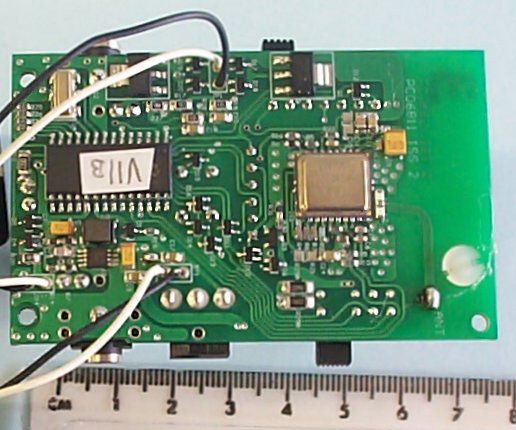
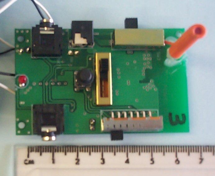
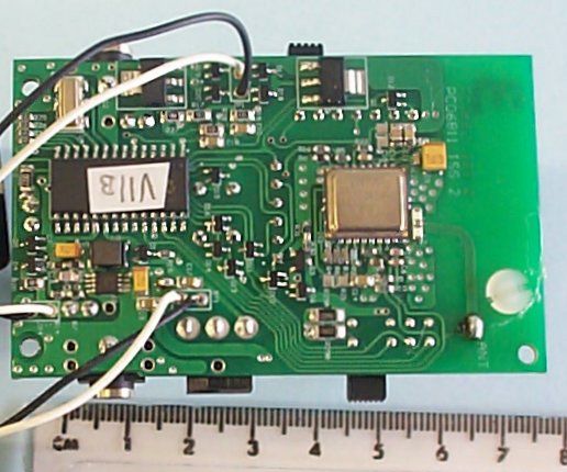
TRL C OMPLIANCE S ERVICES L TD EMC DIVISION LONG GREEN FORTHAMPTON GLOUCESTER GL19 4QH UNITED KINGDOM TELEPHONE +44 (0)1684 833818 FAX +44 (0)1684 833858 E- MAIL [email protected] www.trlcompliance.com 0728 TEST REPORT NO:RU1061/4766 COPY NO: ISSUE NO:1 FCC ID:Q89-5150 REPORT ON THE CERTIFICATION TESTING OF A BOWENS INTERNATIONAL Ltd. Lite Link WITH RESPECT TO THE FCC RULES CFR 47, PART 15.231 INTENTIONAL RADIATOR SPECIFICATION TEST DATE: 19 th – 20 th August 2003 TESTED BY:J CHARTERS APPROVED BY:P GREEN EMC PRODUCT MANAGER DATE: Distribution: Copy Nos:1.BOWENS INTERNATIONAL Ltd. 2.TRL COMPLIANCE SOLUTIONS TCB 3.TRL EMC THIS DOCUMENT MAY BE REPRODUCED ONLY IN ITS ENTIRETY AND WITHOUT CHANGE RF335 iss02RU1061/4766Page 2 of 31 CONTENTS PAGE CERTIFICATE OF CONFORMITY & COMPLIANCE3 APPLICANT’S SUMMARY4 EQUIPMENT TEST CONDITIONS5 TESTS REQUIRED5 TEST RESULTS Transmitter6 - 11 Receiver12 - 15 ANNEX PHOTOGRAPHSA PHOTOGRAPH No. 1: Test setup PHOTOGRAPH No. 2: Test setup PLC PHOTOGRAPH No. 3: Transmitter front view PHOTOGRAPH No. 4: Transmitter rear view PHOTOGRAPH No. 5: Transmitter side view PHOTOGRAPH No. 6: Transmitter side view PHOTOGRAPH No. 7: Transmitter PCB track side PHOTOGRAPH No. 8: Transmitter PCB component side APPLICANT’S SUBMISSION OF DOCUMENTATION LISTB BAND OCCUPANCY PLOTC TRANSMITTER ON TIMED POWERLINE CONDUCTION SCAN DATAE Notes: 1.Component failure during testYES NO [ ] [X] 2.If Yes, details of failure: 3.The facilities used for the testing of the product contain in this report are FCC Listed. 4.The contents of the attached applicants declarations and other supplied information are not covered by the scope of this laboratory’s UKAS or FCC accreditations’ and is provided in good faith. RF335 iss02RU1061/4766Page 3 of 31 CERTIFICATE OF CONFORMITY & COMPLIANCE FCC IDENTITY:Q89-5150 PURPOSE OF TEST:CERTIFICATION TEST SPECIFICATION:FCC RULES CFR 47, Part 15.231 TEST RESULT:Compliant to Specification EQUIPMENT UNDER TEST:Lite Link EQUIPMENT SERIAL No:#1 ITU: EMISSION CODE:166KDAD EQUIPMENT TYPE:CE-5150 PRODUCT USE:Telemetry CARRIER EMISSION: 204.17μV/m @3m ANTENNA TYPE:Integral ALTERNATIVE ANTENNA:Not applicable BAND OF OPERATION:260MHz-470MHz CHANNEL SPACING:Wideband NUMBER OF CHANNELS:1 FREQUENCY GENERATION:SAW Resonator[X]Crystal[ ]Synthesiser [ ] MODULATION METHOD:Amplitude[X]Digital[ ]Angle [ ] POWER SOURCE(s):3Vdc Battery operation 110v ac via AC/DC power brick TEST DATE(s):19 th – 20 th August 20003 ORDER No(s):44884 APPLICANT:BOWENS INTERNATIONAL Ltd. ADDRESS:335 Old Road Clacton on Sea ESSEX CO15 3RH United Kingdom TESTED BY:J CHARTERS APPROVED BY:P GREEN EMC PRODUCT MANAGER RF335 iss02RU1061/4766Page 4 of 31 APPLICANT’S SUMMARY EQUIPMENT UNDER TEST (EUT):Lite Link EQUIPMENT TYPE:CE-5150 SERIAL NUMBER OF EUT:#1 PURPOSE OF TEST:CERTIFICATION TEST SPECIFICATION(s): FCC RULES CFR 47, Part 15.209,151207 15.109,15.107 TEST RESULT:COMPLIANTYes No [X] [ ] APPLICANT’S CATEGORY:MANUFACTURER IMPORTER DISTRIBUTOR TEST HOUSE AGENT [X] [ ] [ ] [ ] [ ] APPLICANT’S ORDER No(s):44884 APPLICANT’S CONTACT PERSON(s):Mr Mark Aherne E-mail address:[email protected] APPLICANT:BOWENS INTERNATIONAL Ltd. ADDRESS:335 Old Road Clacton on Sea Essex CO15 3RH United Kingdom TEL:0044 1255 422807 FAX:00441255 436342 MANUFACTURER:BOWENS INTERNATIONAL Ltd. EUT(s) COUNTRY OF ORIGIN:United Kingdom TEST LABORATORY:TRL EMC UKAS ACCREDITATION No:0728 TEST DATE(s)19 th – 20 th August 2003 TEST REPORT No:RU1061/4766 RF335 iss02RU1061/4766Page 5 of 31 EQUIPMENT TEST / EXAMINATIONS REQUIRED 1. TEST/EXAMINATIONRULE PARTDETECTORAPPLICABILITY Intentional Emission Frequency:15.231(a)Quasi PeakYes Intentional Emission Field Strength:15.231(b)Quasi PeakYes Intentional Emission Band Occupancy:15.231(c)Quasi PeakYes Intentional Emission ERP (mW):N/A-No Spurious Emissions – Conducted:15.207 Quasi Peak/ Average Yes Spurious Emissions – Radiated <1000MHz:15.209Quasi PeakYes Spurious Emissions – Radiated >1000MHz: 15.209 15.231 AverageYes Maximum Frequency of Search:15.33N/AYes Antenna Arrangements Integral:15.203-Yes Antenna Arrangements External Connector:N/AN/ANo Restricted Bands15.205-Yes Extrapolation Factor15.31(f)-No 2.Product Use:Signal control 3.Emission Designator:166KDAD 4.Duty Cycle:<10% 5.Transmitter bit or pulse rate and level:166kbps 6.Temperatures:Ambient (Tnom)22 o C 7.Supply Voltages:Vnom3Vdc Note: Vnom voltages are as stated above unless otherwise shown on the test report page Single channel[X] Two channel[ ] 8.Equipment Category: Multi-channel[ ] Narrowband[ ] Wideband[X] 9.Channel spacing: RF335 iss02RU1061/4766Page 6 of 31 TRANSMITTER TESTS TRANSMITTER SPURIOUS EMISSIONS – RADIATED – PART 15.209 Ambient temperature=22 o C(<1GHz)3m measurements <1GHz[X] Relative humidity=60% (<1GHz),0.3m measurements >1GHz[X] Conditions=Open Area Test Site (OATS)3m extrapolated from 0.3m[ ] Supply voltage=3V Channel number=1 FREQ. (MHz) MEAS. Rx. (dBμV) CABLE LOSS (dB) ANT FACTOR (dB/m) FIELD STRENGTH (dBμV/m) EXTRAP. FACTOR (dB) FIELD STRENGTH (μV/m) 30MHz- 88MHz 88MHz-216MHz 216MHz-960MHz867.8504-1.43.420.122.1-12.73 960MHz-1GHz 1GHz-5GHz 1.705MHz to 30MHz 30μV/m@ 30m 30MHz to 88MHz100μV/m@ 3m 88MHz to 216MHz150μV/m@ 3m 216MHz to 960MHz200μV/m@ 3m 960MHz to 1GHz500μV/m@ 3m Limits 1GHz to 5GHz500μV/m@ 3m Notes: 1Results quoted are extrapolated as indicated 2Emissions were searched to: 5000MHz inclusive, as per Part 15.33a 3Extrapolation factor 9.5dB from 1m to 3m, as per Part 15.31f 4Measurements >1GHz @ 1m as per Part 15.31f(1) 5Receiver detector >1GHz = CISPR, Quasi-Peak, 120kHz bandwidth 6Receiver detector >1GHz = Peak Hold, 1MHz resolution bandwidth 7New batteries used for battery powered products. 8Only emissions within 10dB of limit are recorded 9 R indicates frequencies within the restricted band from Part15.205 10During the test program the Lite Link was connected to the following peripheral units: Switch/Camera trigger port. 1m cable AC/DC power supply. 1.5m 2 core cable Load cables were attached to…
Text truncated - open the document above for the full version.
Contact Information
Applicant
Mark Aherne(Technical Manager)
Test Firm
TRL EMC LimitedNeil Roche
Technical Specifications
| # | Rule Parts | Frequency Range | Power Output |
|---|---|---|---|
| 1 | 15.231 | 433.92 MHz - 433.92 MHz | - |
Other Applications from Bowens International Limited

Q89-3965
Mar 14, 2011Remote Camera Trigger
Equipment Class
DSR - Part 15 Remote Control/Security Device Transceiver