Q8NAWT2400G802.11 b/g Wireless LAN Card
AIN COMM. Technology Co., Ltd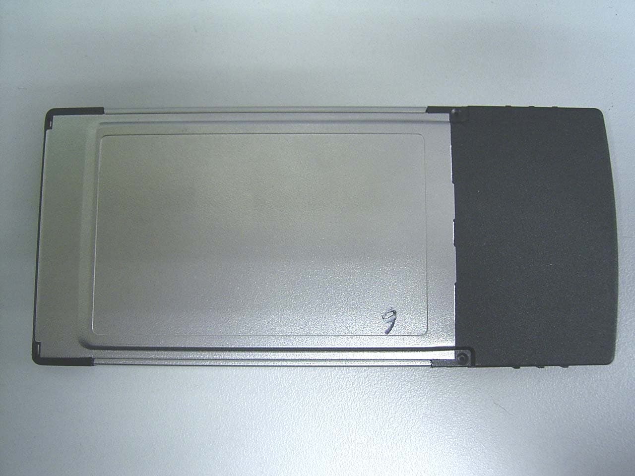
Click to zoom
Application Details
- Equipment Class
- DTS - Digital Transmission System
- Date of Grant
- May 06, 2004
- Application Purpose
- Original Equipment
- Date of Application
- May 06, 2004
- Equipment Note
- 802.11 b/g Wireless LAN Card
- Frequency Range
- 2412.00000000 - 2462.00000000
- Country
- Taiwan
Documents & Files
Document Text
Text extracted from the exhibit documents filed with the FCC. Open a document above to read the original.
Users Manual
AIN AWT2400G WIRELESS LAN AIR HUNTER 802.11G/B 54/MBPS User Manual Federal Communications Commission Statement Installation and use of this Wireless LAN device must be in strict accordance with the instructions included in the user documentation provided with the product. Any changes or modifications (including the antennas) made to this device that are not expressly approved by the manufacturer may void the user’s authority to operate the equipment. The manufacturer is not responsible for any radio or television interference caused by unauthorized modification of this device, or the substitution of the connecting cables and equipment other than manufacturer specified. It is the responsibility of the user to correct any interference caused by such unauthorized modification, substitution or attachment. Manufacturer and its authorized resellers or distributors will assume no liability for any damage or violation of government regulations arising from failing to comply with these guidelines. This device complies with FCC Rules Part 15. Operation is subject to the following two conditions: . • This device may not cause harmful interference, and . • This device must accept any interference received, including interference that may cause undesired operation. This equipment has been tested and found to comply with the limits for a class B digital device, pursuant to Part 15 of the Federal Communications Commission (FCC) rules. These limits are designed to provide reasonable protection against harmful interference in a residential installation. This equipment generates, uses, and can radiate radio frequency energy and, if not installed and used in accordance with the instructions, may cause harmful interference to radio communications. However, there is no guarantee that interference will not occur in a particular installation. If this equipment does cause harmful interference to radio or television reception, which can be determined by turning the equipment off and on, the user is encouraged to try to correct the interference by one or more of the following measures: . • Reorient or relocate the receiving antenna. . • Increase the separation between the equipment and receiver. . • Connect the equipment into an outlet on a circuit different from that to which the receiver is connected. . • Consult the dealer or an experienced radio/TV technician for help. SAR Exposure This device has been tested for compliance with FCC RF Exposure (SAR) limits in typical flat configurations. IMPORTANT NOTE FCC RF Radiation Exposure Statement: This equipment complies with FCC RF radiation exposure limits set forth for an uncontrolled environment. This device and its antenna must not be co-located or operating in conjunction with any other antenna or transmitter. European Notice Products with the CE Marking comply with both the EMC Directive (89/336/EEC) and the Low Voltage Directive (73/23/EEC) issued by the Commission of the European Community. Compliance with these directives implies conformity to the following European Norms: z EN 55022 ( CISPR 22) radio Frequency Interference z EN 55024 ( EN61000-4-2, EN61000-4-3, EN61000-4-4, EN61000-4-5, EN61000-4-6, EN61000-4-8, EN61000-4-11, EN61000-3-2, EN61000-3-3) Generic Immunity Standard. z EN 60950 ( IEC950) Product Standard. Regulatory statement (R&TTE / WLAN IEEE 802.11b & 802.11g) European standards dictate maximum radiated transmit power of 100mW EIRP and frequency range 2.400-2.4835GHz; In France, the equipment must be restricted to the 2.4465-2.4835GHz frequency range and must be restricted to indoor use. CE Declaration of Conformity For the followi ng equi pment: AIN AWT2400g Cardbus Wireless LAN Card ! 0984 Is herewith confirmed to comply with the requirements set out in the Council Directive on the Approximation of the Laws of the Member States relating to Electromagnetic Compatibility (89/336/EEC), Low-voltage Directive (73/23/EEC) and the Amendment Directive (93/68/EEC), the procedures given in European Council Directive 99/5/EC and 89/3360EEC. The equipment was passed. The test was performed according to the following European standards: z EN 300 328-2 V.1.2.1 (2001-08) z EN 301 489-1 V.1.4.1 (2002-04) / EN 301 489-17 V.1.2.1 (2002-04) z EN 50371: 2002 z EN 60950: 2000 AWT2400g Wireless LAN CARD 1 Content 1. Product Introduction............................................................................................2 2. Air Hunter Installation.........................................................................................4 3. Ad-Hoc (Peer-to-Peer) Mode Setup........................................................................13 Application 1: Access the Internet without an AP Application 2: Data sharing between computers 4. Technical Support..............................................................................................22 AWT2400g Wireless LAN CARD 2 1. Product Introduction Thank you for using Air Hunter WLAN product. This installation guide will help you install Air Hunter WLAN Card and connect to the Internet quick & easy. ■ Package Contents 1. AIR HUNTER WLAN CARD 2. Quick Installation Guide 3. Driver CD Disc ■ Form Factor 1- Internal High gain Antenna_1 2- Green color LED is “LINK” 3- Yellow color LED is “ACT” 4- Internal High gain Antenna_2 ■ System Requirements 1. Laptop or Other with Cardbus(PCMCIA-II)port and CD-ROM driver 2. Operating System: Windows 98 SE / ME / 2000 / XP AWT2400g Wireless LAN CARD 3 ■ Applied Environments There are two application modes for this WLAN card, the “Ad-Hoc mode” and the “Infrastructure mode”. (For further explain, please refer to the “WLAN Application Modes” below) Different modes require different settings. Please check the environment first. Infrastructure mode: Via “Access Point” (AP) to connect to the Internet. This mode further gives wireless access to Internet or data sharing under a previously wired environment. Ad-Hoc mode: Connecting to other computer with WLAN card. This mode …
Text truncated - open the document above for the full version.
Cover Letter(s)
Mike Kuo From: [email protected] Sent: May05 2004 Wednesday 7:34 PM To: Mike Kuo Cc: [email protected] Subject: RE: AIN Communication Technology Co., Ltd, FCC ID:Q8NAWT2400G, AN 04T3842 5/7/2004 Hi Mike, Reply to Question #2: It is not acceptable. A statement to inform "The channel number over 11 is not allowed in the USA." is not going to address compliance issue. This question is related to Question #3 that I asked. Base upon the description of software that used by the PCMCIA card, once the reg. domain is changed, the channel list will change as well. The applicant can not depend on the end user to select the correct channel range, the applicant has to PREVENT the end user to have option to choose any unauthorized channel list. Reply to Question #3: It is not acceptable. "The field of Reg Domain cannot be changed. It must be authorized by the local government. " What do you mean authorized by the local government ? The software package that sold with this PCMCIA card in the U.S. shall not provide option for end user to choose Reg. Domain and channel list above 11 channel. Please provide revised user manual and statement from AIN Communication to ensure product compliance. Our Response: The user manual is revised. Please refer to it. Hi Ting : Reply to Question #1: O.K. Reply to Question #2: It is not acceptable. A statement to inform "The channel number over 11 is not allowed in the USA." is not going to address compliance issue. This question is related to Question #3 that I asked. Base upon the description of software that used by the PCMCIA card, once the reg. domain is changed, the channel list will change as well. The applicant can not depend on the end user to select the correct channel range, the applicant has Mike Kuo <[email protected]> 2004/04/30 02:20 AM "'[email protected]'" <[email protected]>, Mike Kuo <[email protected]> [email protected], "Lai, Harris (E-mail)" <[email protected]>, Scott Wang <[email protected]> to PREVENT the end user to have option to choose any unauthorized channel list. Reply to Question #3: It is not acceptable. "The field of Reg Domain cannot be changed. It must be authorized by the local government. " What do you mean authorized by the local government ? The software package that sold with this PCMCIA card in the U.S. shall not provide option for end user to choose Reg. Domain and channel list above 11 channel. Please provide revised user manual and statement from AIN Communication to ensure product compliance. Best Regards Mike Kuo Hi Mike, Question #1: Page 2 of user manual stated "Radio Frequency Interference Requirements This device is restricted to INDOOR USE due to it's operation in the 2.4 to 2.4835 GHz frequency range. According to FCC 15.247(e), requires this product to be used indoors for the frequency range 2.40 to 2.4835 GHz to reduce the potential for harmful interference to co-channel of the Mobile Satellite Systems." There is no Section 15.247(e), above statement is not required for 15.247 2.4GHz device. Please remove this statement. The user manual does not contain RF exposure warning statement for the restriction of non-co-location with other antenna and transmitter, please provide revised user manual to comply this requirement. Ans #1: The user manual is re-done. Please be advised that the statement of FCC 15.247(e) is removed and the RF exposure warning statement of the restriction of non-co-location with other antenna and transmitter is provided. Question #2: Page 16 of user manual provides the channel number above 11 channel , this device only investigated up to 11 channel, any channel operation above 11 channel is not allowed. Please address this non-compliance issue. Ans #2: The user manual is revised to address this issue. Please refer to it. Question #3 : Page 8 of user manual provides the option for user to select the Reg. Domain which may enable the end user to operate in the unauthorized channel. Please address this non-compliance issue. Ans #3: TThe user manual is revised to address this issue. Please refer to it. -----Original Message----- From: [email protected] [mailto:[email protected]] Sent: Wednesday, April 28, 2004 7:14 PM To: Mike Kuo Cc: [email protected]; [email protected] Subject: FW: AIN Communication Technology Co., Ltd, FCC ID:Q8NAWT2400G, AN 04T3842 5/7/2004
External Photos
Compliance Certification Services Inc. Report No: B40226602 Date of Issue: March 4, 2004 Page 1 of 3 External Photo
ID Label/Location Info
AIN AWT2400g Cardbus Wireless Lan Card FCC ID: Q8NAWT2400G Tested to Comply With FCC Standards FOR HOME OR OFFICE USE This device complies with Part 15 of the FCC Rules. Operation is subject to the following two conditions: (1)This device may not cause harmful interference. (2)This device must accept any interference received, including interference that may cause undesired operation. MAC : XXXXXXXXXXXX S/N : XXXXXXXXXXXXXX
Internal Photos
Compliance Certification Services Inc. Report No: B40226602 Date of Issue: March 4, 2004 Page 2 Internal Photo Compliance Certification Services Inc. Report No: B40226602 Date of Issue: March 4, 2004 Page 3
Parts List/Tune Up Info
AIN Communication Technology Co., Ltd 展駿電通科技股份有限公司 Tel : 886-3-4938448 Fax : 886-3-4938804 Add : 4F, No.76, Sec.2, Mintzu Rd, Jungli City, Taoyuan 320, Taiwan, R.O.C. AIN Communication Technology Co., Ltd. Tel: 886-3-4938448 Fax: 886-3-4938804 http://www.aincomm.com.tw/ ● Brand/model number : AIN / AWT2400ANT ● Antenna gain : Average gain : -4.75dBi ( @ 6dB band-width ), Peak gain : 1.89dBi . ● Antenna type : Diversity PIFA (Planar Inverted-F Antenna ). ● Size : L=10.25 mm, W=6.25 mm, H= t = 0.6 mm. ● Wave pattern :
RF Exposure Info
Compliance Certification Services Inc. Report No: B40226602-SF Date of Issue: March 04, 2004 Note: This report shall not be reproduced except in full, without the written approval of Compliance Certification Services Inc. This document may be altered or revised by Compliance Certification Services Inc. personnel only, and shall be noted in the revision section of the document. Page1 of 22 ANSI/IEEE Std. C95.1-1992 in accordance with the requirements of FCC Report and Order: ET Docket 93-62, and OET Bulletin 65 Supplement C TEST REPORT For AIN Communication Technology Co., Ltd. Cardbus Wireless Lan Card Model: AWT2400g (Trade Name: AIN ) Model: WWPC54g (Trade Name: Wanshih ) Prepared for AIN Communication Technology Co., Ltd 4F, No.76, Sec.2, Mintzu Rd, Jungli City, Taoyuan 320, Taiwan, R.O.C. Prepared by Compliance Certification Services Inc. No. 81-1, Lane 210, Bade Rd. 2, Luchu Hsiang, Taoyuan Hsien, (338) Taiwan, R.O.C. TEL: 886-3-324-0332 FAX: 886-3-324-5235 Compliance Certification Services Inc. Report No: B40226602-SF Date of Issue: March 04, 2004 TABLE OF CONTENTS 1. EUT DESCRIPTION.....................................................................................................4 2. REQUIREMENTS FOR COMPLIANCE TESTING DEFINED BY THE FCC....5 3. DOSIMETRIC ASSESSMENT SYSTEM...................................................................5 3.1 MEASUREMENT SYSTEM DIAGRAM.........................................................................6 3.2 SYSTEM COMPONENTS.................................................................................................7 DASY4 Measurement Server.............................................................................................7 Data Acquisition Electronics (DAE)..................................................................................7 ET3DV6 Isotropic E-Field Probe for Dosimetric Measurements......................................7 SAM Phantom (V4.0)........................................................................................................8 Device Holder for SAM Twin Phantom............................................................................8 System Validation Kits......................................................................................................8 4. EVALUATION PROCEDURES................................................................................... 9 5. MEASUREMENT UNCERTAINTY.........................................................................12 6. EXPOSURE LIMIT.....................................................................................................13 7. MEASUREMENT RESULTS.....................................................................................14 7.1 SYSTEM PERFORMANCE CHECK..............................................................................14 7.2 TEST LIQUID CONFIRMATION...................................................................................15 7.3 EUT TUNE-UP PROCEDURES......................................................................................16 7.4 SAR MEASUREMENTS RESULTS...............................................................................17 8. EUT PHOTOS..............................................................................................................19 9. EQUIPMENT LIST & CALIBRATION STATUS...................................................20 10. REFERENCES.............................................................................................................21 11. ATTACHMENTS.........................................................................................................22 Page 3 Compliance Certification Services Inc. Report No: B40226602-SF Date of Issue: March 04, 2004 1. EUT DESCRIPTION Applicant: AIN Communication Technology Co., Ltd 4F, No.76, Sec.2, Mintzu Rd, Jungli City, Taoyuan 320, Taiwan, R.O.C. Model Number: AWT2400g Wireless Lan FCC ID: Q8NAWT2400G Device Category: PORTABLE DEVICES Exposure Category: GENERAL POPULATION/UNCONTROLLED EXPOSURE Test Sample is a: Production unit Modulation type: 802.11b Direct Sequence Spread Spectrum 802.11g Orthogonal Frequency Division Multiplexing (OFDM) Tx Frequency: 2412 ~ 2462 MHz Max. O/P Power: (Conducted/Peak) 19.10dBm Max. SAR (1g): 0.322W/kg Application Type: Certification FCC Rule Part(s): 15C Antennas: Printed Ant. Test Host: LEO P/N: M285 S/N:1A25B37A002110 Page 4 Compliance Certification Services Inc. Report No: B40226602-SF Date of Issue: March 04, 2004 2. REQUIREMENTS FOR COMPLIANCE TESTING DEFINED BY THE FCC The US Federal Communications Commission has released the report and order “Guidelines for Evaluating the Environmental Effects of RF Radiation", ET Docket No. 93-62 in August 1996 [1]. The order requires routine SAR evaluation prior to equipment authorization of portable transmitter devices, including portable telephones. For consumer products, the applicable limit is 1.6 mW/g for an uncontrolled environment and 8.0 mW/g for an occupational/controlled environment as recommended by the ANSI/IEEE standard C95.1-1992 [6]. According to the Supplement C of OET Bulletin 65 “Evaluating Compliance with FCC Guide-lines for Human Exposure to Radio frequency Electromagnetic Fields", released on Jun 29, 2001 by the FCC, the device should be evaluated at maximum output power (radiated from the antenna) under “worst-case” conditions for normal or intended use, incorporating normal antenna operating positions, device peak performance frequencies and positions for maximum RF energy coupling. 3. DOSIMETRIC ASSESSMENT SYSTEM These measurements were performed with the automated near-field scanning system DASY4 from Schmid & Partner Engineering AG (SPEAG). The system is based on a high precision robot (working range greater than 0.9 m) which positions the probes with a positional repeatability of better than ± 0.02 mm. Special E- and H-field probes have been developed for measurements close to material discontinuity, the sensors o…
Text truncated - open the document above for the full version.
RF Exposure Info
Date/Time: 03/01/04 12:34:00 Test Laboratory: Compliance Certification Services Inc. D2450V2 SN 728 DUT: Dipole 2450 MHz; Type: D2450V2; Serial:728 Communication System: CW2450; Frequency: 2450 MHz;Duty Cycle: 1:1 Medium: HSL2450 (σ = 1.811 mho/m, ε r = 39, ρ = 1000 kg/m 3 ) Air Temperature 25.2 deg C ;Liquid Temperature 24 deg C Phantom section: Flat Section DASY4 Configuration: z Probe: ET3DV6 - SN1762; ConvF(5.1, 5.1, 5.1); Calibrated: 3/31/2003 z Sensor-Surface: 4mm (Mechanical Surface Detection) Sensor-Surface: 0mm (Fix Surface) Sensor-Surface: 4mm (Mechanical And Optical Surface Detection) z Electronics: DAE3 Sn558; Calibrated: 3/7/2003 z Phantom: SAM 34; Type: SAM V4.0; Serial: TP-1150 z Measurement SW: DASY4, V4.1 Build 47; Postprocessing SW: SEMCAD, V1.8 Build 62 Pin=250mW,d=10mm/Area Scan (6x6x1): Measurement grid: dx=15mm, dy=15mm Reference Value = 96.8 V/m Power Drift = 0.0 dB Maximum value of SAR = 11.1 mW/g Pin=250mW,d=10mm/Z Scan (1x1x21): Measurement grid: dx=20mm, dy=20mm, dz=5mm Reference Value = 96.8 V/m Power Drift = 0.0 dB Maximum value of SAR = 23 mW/g Pin=250mW,d=10mm/Zoom Scan (5x5x7)/Cube 0: Measurement grid: dx=7.5mm, dy=7.5mm, dz=5mm Peak SAR (extrapolated) = 30.5 W/kg SAR(1 g) = 14.1 mW/g; SAR(10 g) = 6.5 mW/g Reference Value = 96.8 V/m Power Drift = 0.0 dB Maximum value of SAR = 15.9 mW/g Page1 Page2 Date/Time: 03/01/04 15:35:04 Test Laboratory: Compliance Certification Services Inc. Test Configuration-1 Page1 Date/Time: 03/01/04 15:35:04 Test Laboratory: Compliance Certification Services Inc. Touch mode(with Compaq) DUT: 802.11b Wireless LAN P3 Detachable Antenna PCMCIA Cardbus Card ; Type: WN- 113SH18; Serial: N/A Communication System: 802.11b Wireless LAN Cardbus PC Card ; Frequency: 2412 MHz;Duty Cycle: 1:1 Medium: BSL2450 (σ = 2 mho/m, ε r = 51, ρ = 1000 kg/m 3 ) Air Temperature 25.2 deg C ;Liquid Temperature 24 deg C Phantom section: Flat Section DASY4 Configuration: z Probe: ET3DV6 - SN1762; ConvF(4.6, 4.6, 4.6); Calibrated: 3/31/2003 z Sensor-Surface: 4mm (Mechanical And Optical Surface Detection) Sensor-Surface: 0mm (Fix Surface) z Electronics: DAE3 Sn558; Calibrated: 3/7/2003 z Phantom: SAM 12; Type: SAM V4.0; Serial: TP-1271 z Measurement SW: DASY4, V4.1 Build 47; Postprocessing SW: SEMCAD, V1.8 Build 62 Low Rate=11M bit/Area Scan (7x10x1): Measurement grid: dx=15mm, dy=15mm Reference Value = 12.4 V/m Power Drift = 0.2 dB Maximum value of SAR = 0.379 mW/g Low Rate=11M bit/Z Scan (1x1x21): Measurement grid: dx=20mm, dy=20mm, dz=5mm Reference Value = 12.4 V/m Power Drift = 0.2 dB Maximum value of SAR = 0.404 mW/g Low Rate=11M bit/Zoom Scan (5x5x7)/Cube 0: Measurement grid: dx=7.5mm, dy=7.5mm, dz=5mm Peak SAR (extrapolated) = 0.885 W/kg SAR(1 g) = 0.427 mW/g; SAR(10 g) = 0.217 mW/g Reference Value = 12.4 V/m Power Drift = 0.2 dB Maximum value of SAR = 0.467 mW/g Page1 Page2 Date/Time: 03/01/04 15:35:04 Test Laboratory: Compliance Certification Services Inc. Touch mode(with Compaq) DUT: 802.11b Wireless LAN P3 Detachable Antenna PCMCIA Cardbus Card ; Type: WN- 113SH18; Serial: N/A Communication System: 802.11b Wireless LAN Cardbus PC Card ; Frequency: 2437 MHz;Duty Cycle: 1:1 Medium: BSL2450 (σ = 2 mho/m, ε r = 51, ρ = 1000 kg/m 3 ) Air Temperature 25.2 deg C ;Liquid Temperature 24 deg C Phantom section: Flat Section DASY4 Configuration: z Probe: ET3DV6 - SN1762; ConvF(4.6, 4.6, 4.6); Calibrated: 3/31/2003 z Sensor-Surface: 4mm (Mechanical And Optical Surface Detection) Sensor-Surface: 0mm (Fix Surface) z Electronics: DAE3 Sn558; Calibrated: 3/7/2003 z Phantom: SAM 12; Type: SAM V4.0; Serial: TP-1271 z Measurement SW: DASY4, V4.1 Build 47; Postprocessing SW: SEMCAD, V1.8 Build 62 mid Rate=11M bit/Area Scan (7x6x1): Measurement grid: dx=15mm, dy=15mm Reference Value = 12.9 V/m Power Drift = -0.2 dB Maximum value of SAR = 0.337 mW/g mid Rate=11M bit/Z Scan (1x1x21): Measurement grid: dx=20mm, dy=20mm, dz=5mm Reference Value = 12.9 V/m Power Drift = -0.2 dB Maximum value of SAR = 0.355 mW/g mid Rate=11M bit/Zoom Scan (5x5x7)/Cube 0: Measurement grid: dx=7.5mm, dy=7.5mm, dz=5mm Peak SAR (extrapolated) = 0.826 W/kg SAR(1 g) = 0.397 mW/g; SAR(10 g) = 0.200 mW/g Reference Value = 12.9 V/m Power Drift = -0.2 dB Maximum value of SAR = 0.427 mW/g Page1 Page2 Date/Time: 03/01/04 15:35:04 Test Laboratory: Compliance Certification Services Inc. Touch mode(with Compaq) DUT: 802.11b Wireless LAN P3 Detachable Antenna PCMCIA Cardbus Card ; Type: WN- 113SH18; Serial: N/A Communication System: 802.11b Wireless LAN Cardbus PC Card ; Frequency: 2462 MHz;Duty Cycle: 1:1 Medium: BSL2450 (σ = 2 mho/m, ε r = 51, ρ = 1000 kg/m 3 ) Air Temperature 25.2 deg C ;Liquid Temperature 24 deg C Phantom section: Flat Section DASY4 Configuration: z Probe: ET3DV6 - SN1762; ConvF(4.6, 4.6, 4.6); Calibrated: 3/31/2003 z Sensor-Surface: 4mm (Mechanical And Optical Surface Detection) Sensor-Surface: 0mm (Fix Surface) z Electronics: DAE3 Sn558; Calibrated: 3/7/2003 z Phantom: SAM 12; Type: SAM V4.0; Serial: TP-1271 z Measurement SW: DASY4, V4.1 Build 47; Postprocessing SW: SEMCAD, V1.8 Build 62 High Rate=11M bit/Area Scan (7x6x1): Measurement grid: dx=15mm, dy=15mm Reference Value = 11.3 V/m Power Drift = -0.4 dB Maximum value of SAR = 0.221 mW/g High Rate=11M bit/Z Scan (1x1x21): Measurement grid: dx=20mm, dy=20mm, dz=5mm Reference Value = 11.3 V/m Power Drift = -0.5 dB Maximum value of SAR = 0.216 mW/g High Rate=11M bit/Zoom Scan (5x5x7)/Cube 0: Measurement grid: dx=7.5mm, dy=7.5mm, dz=5mm Peak SAR (extrapolated) = 0.496 W/kg SAR(1 g) = 0.238 mW/g; SAR(10 g) = 0.121 mW/g Reference Value = 11.3 V/m Power Drift = -0.4 dB Maximum value of SAR = 0.256 mW/g Page1 Page2 Date/Time: 03/03/04 20:03:38 Test Laboratory: Compliance Certification Services Inc. Test Configuration-2 Page1 Date/Time: 03/01/04 16:33:51 Test Laboratory: Compliance Certification Services Inc. 15mm mode(with Compaq) DUT: 802.11b Wireless LAN P3 Detachable Antenna PCMCIA Cardbus Card ; Type: WN- 113SH18; Serial: N/A Communicatio…
Text truncated - open the document above for the full version.
Test Report
Compliance Certification Services Inc. Report No: B40226602-RP FCC ID: Q8NAWT2400G Date of Issue: March 5, 2004 Note: This report shall not be reproduced except in full, without the written approval of Compliance Certification Services Inc. This document may be altered or revised by Compliance Certification Services Inc. personnel only, and shall be noted in the revision section of the document. Page 1 of 63 FCC 47 CFR PART 15 SUBPART C TEST REPORT For AIN Communication Technology Co., Ltd Cardbus Wireless Lan Card Model: AWT2400g, WWPC54G Trade Name: AIN, Wanshih Prepared for AIN Communication Technology Co., Ltd. 4F, No. 76, Sec. 2, Mintzu Rd, Jungli City, Taoyuan 320, Taiwan, R.O.C. Prepared by Compliance Certification Services Inc. No. 81-1, Lane 210, Bade Rd. 2, Luchu Hsiang, Taoyuan Hsien, (338) Taiwan, R.O.C. TEL: 886-3-324-0332 FAX: 886-3-324-5235 Compliance Certification Services Inc. Report No: B40226602-RP FCC ID: Q8NAWT2400G Date of Issue: March 5, 2004 Page 2 TABLE OF CONTENTS 1. TEST RESULT CERTIFICATION............................................................................................. 3 2. EUT DESCRIPTION .................................................................................................................... 4 3. TEST METHODOLOGY ............................................................................................................. 5 3.1 EUT CONFIGURATION...................................................................................................................5 3.2 EUT EXERCISE...............................................................................................................................5 3.3 GENERAL TEST PROCEDURES........................................................................................................5 3.4 FCC PART 15.205 RESTRICTED BANDS OF OPERATIONS...................................................6 3.5 DESCRIPTION OF TEST MODES......................................................................................................6 4. INSTRUMENT CALIBRATION................................................................................................. 7 5. FACILITIES AND ACCREDITATIONS ................................................................................... 8 5.1 FACILITIES ....................................................................................................8 5.2 EQUIPMENT...................................................................................................................................8 5.3 LABORATORY ACCREDITATIONS AND LISTING.............................................................................8 5.4 TABLE OF ACCREDITATIONS AND LISTINGS..................................................................................9 6. SETUP OF EQUIPMENT UNDER TEST ................................................................................ 10 6.1 SETUP CONFIGURATION OF EUT..................................................................................................10 6.2 SUPPORT EQUIPMENT ..........................................................................................................10 7. FCC PART 15.247 REQUIREMENTS...................................................................................... 11 7.1 6DB BANDWIDTH........................................................................................................................11 7.2 PEAK POWER...............................................................................................................................16 7.3 BAND EDGES MEASUREMENT ...........................................................................................21 7.4 PEAK POWER SPECTRAL DENSITY...............................................................................................30 7.5 RADIO FREQUENCY EXPOSURE...................................................................................................35 7.6 SPURIOUS EMISSIONS ...........................................................................................................36 7.7 POWERLINE CONDUCTED EMISSIONS..........................................................................................58 Compliance Certification Services Inc. Report No: B40226602-RP FCC ID: Q8NAWT2400G Date of Issue: March 5, 2004 Page 4 2. EUT DESCRIPTION Product Cardbus Wireless Lan Card Trade Name AIN, Wanshih Model Number AWT2400g, WWPC54G Model difference All the above models are identical except the model designation Module Trade Name INPROCOMM Module Model Number IPN2220 Model Discrepancy N/A Power Supply Powered from host device Frequency Range IEEE 802.11b,g: 2412 ~ 2462 MHz Transmit Power IEEE 802.11b: 19.05 dBm IEEE 802.11g: 19.05 dBm Modulation Technique IEEE 802.11b: DSSS (CCK; DQPSK; DBPSK) IEEE 802.11g: OFDM Antenna Gain 1.89 dBi (Max) Antenna Designation Diversity PIFA (Planar Inverted-F Antenna) Note: This submittal(s) (test report) is intended for FCC ID: Q8NAWT2400G filing to comply with Section 15.207, 15.209 and 15.247 of the FCC Part 15, Subpart C Rules. Compliance Certification Services Inc. Report No: B40226602-RP FCC ID: Q8NAWT2400G Date of Issue: March 5, 2004 Page 5 3. TEST METHODOLOGY The tests documented in this report were performed in accordance with ANSI C63.4 and FCC CFR 47 2.1046, 2.1047, 2.1049, 2.1051, 2.1053, 2.1055, 2.1057, 15.207, 15.209 and 15.247. 3.1 EUT CONFIGURATION The EUT configuration for testing is installed on RF field strength measurement to meet the Commissions requirement and operating in a manner that intends to maximize its emission characteristics in a continuous normal application. 3.2 EUT EXERCISE The EUT was operated in the engineering mode to fix the TX frequency that was for the purpose of the measurements. According to its specifications, the EUT must comply with the requirements of the Section 15.247 under the FCC Rules Part 15 Subpart C. 3.3 GENERAL TEST PROCEDURES Conducted Emissions The EUT is plac…
Text truncated - open the document above for the full version.
Test Setup Photos
Compliance Certification Services Inc. Report No: B40226602-RP FCC ID: Q8NAWT2400G Date of Issue: March 5, 2004 Page 62 APPENDIX 1 PHOTOGRPHS OF TEST SETUP Radiated Emission Set up Photos Compliance Certification Services Inc. Report No: B40226602-RP FCC ID: Q8NAWT2400G Date of Issue: March 5, 2004 Page 63 Conducted Emission Set Up Photos
Contact Information
Applicant
Dr. Ming-Yi Lay(Manager)
Test Firm
Compliance Certification Services Inc.Tony Houng
Technical Specifications
| # | Rule Parts | Frequency Range | Power Output |
|---|---|---|---|
| 1 | 15C | 2.41 GHz - 2.46 GHz | 80.40 mW |
Other Applications from AIN COMM. Technology Co., Ltd

Q8NAWU2000B
Aug 10, 20032.4GHz WLAN USB Stick
Equipment Class
DTS - Digital Transmission System