Q9FPX-328UUHF Portable 2Way Radio
Holzberg Communications, Inc.
Click to zoom
Application Details
- Equipment Class
- TNF - Licensed Non-Broadcast Transmitter Held to Face
- Date of Grant
- Dec 12, 2007
- Application Purpose
- Original Equipment
- Date of Application
- Sep 24, 2007
- Equipment Note
- UHF Portable 2Way Radio
- Frequency Range
- 450.00000000 - 512.00000000
- Country
- United States
Documents & Files
Document Text
Text extracted from the exhibit documents filed with the FCC. Open a document above to read the original.
Users Manual
2 of 27 3 of 27 Maintenance Your Two Way Radio is an electronic product of exact design and should be treated with care .The suggestions below will help you to fulfill any warranty obligations and to enjoy this product for many years. z Do not attempt to open the unit. Non-expert handling of the unit may damage it. z When using regulated power supply, take notice of power voltage must be between 6V and 8V to avoid damaging the unit. z Do not store the Radio under the sunshine or in hot areas. High temperatures can shorten the life of electronic devices, and warp or melt certain plastics. z Do not store the Radio in dusty, dirty areas z Keep the Radio dry. Rainwater or damp will corrode electronic circuits. z If it appears that the Radio diffuses peculiar smell or smoke, please shut off its power immediately and take off charger or battery in the Radio, then contact with PUXING agency. z Do not transmit without antenna. Feature UHF4W Output power 118 groups of memory channels. 12.5KHz Channel spacing Automatic Numbering Identification (ANI) code Built-in Voice Operate Transmit (VOX) function. All channels scan and priority channel scan Scrambler Three color LCD backlight adjustable Emergency alarm Programmable by pc with software 50 CTCSS and 104 DCS Normal/Inverted selectable Time-out Timer (TOT) Busy channel lockout 4 of 27 6 of 27 7 of 27 8 of 27 9 of 27 10 of 27 11 of 27 12 of 27 13 of 27 14 of 27 15 of 27 16 of 27 17 of 27 18 of 27 19 of 27 20 of 27 21 of 27 22 of 27 23 of 27 24 of 27 User Safety, Training, and General Information z READ THIS IMPORTANT INFORMATION ON SAFE AND EFFICIENT OPERATION BEFORE USING YOUR PUXING PORTABLE TWO-WAY RADIO. Operational Instructions and Training Guidelines To ensure optimal performance and compliance with the occupational/controlled environment RF energy exposure limits in the above standards and guidelines, users should transmit no more than 50% of the time and always adhere to the following procedures: Transmit and Receive To transmit (talk), push the Push-To-Talk (PTT) button; to receive, release the PTT button. Hand-held radio operation Hold the radio in a vertical position with the microphone one to two inches (2.5 to 5 cm) away from the lips. FCC Compliance This equipment has been tested and found to comply with the limits for a Class B digital device, pursuant to part 90 of the FCC Rules. These limits are designed to provide reasonable protection against harmful interference in a residential installation. This equipment generates, uses and can radiate radio frequency energy and, if not installed and used in accordance with the instructions, may cause harmful interference to radio communications. However, there is no guarantee that interference will not occur in a particular installation. If this equipment does cause harmful interference to radio or television reception, which can be determined by turning the equipment off and on, the user is encouraged to try to correct the interference by one or more of the following measures: · Reorient or relocate the receiving antenna. · Increase the separation between the equipment and receiver. · Connect the equipment into an outlet on a circuit different from that to which the receiver is connected. · Consult the dealer or an experienced radio/TV technician for help. FCC Requirements Your radio must be properly licensed Federal Communications Commission prior to use. Your dealer can assist you in meeting these requirements. Your dealer will program each radio with your authorized frequencies, signaling codes, etc., and will be there to meet your communications needs as your system expands. Safety: It is important that the operator is aware of and understands hazards common to the operation of any radio. READ THIS IMPORTANT INFORMATION ON SAFE AND EFFICIENT OPERATION BEFORE USING YOUR HYT PORTABLE TWO-WAY RADIO. ◇ Only qualified technicians are allowed to maintain this product. ◇ To avoid electromagnetic interference and/or compatibility conflicts, turn off your radio in any place where posted notices instruct you to do so. Hospitals or health care facilities may be using equipment that is sensitive to external RF energy. When on aircraft, turn off your radio when airline crew instruct you to do so. ◇ When in vehicles with an airbag, do not place a portable radio in the area over an airbag or in the airbag deployment area. ◇ Turn off your radio prior to entering any area with a potentially explosive atmosphere. Do not remove, install, or charge batteries in such areas. ◇ To avoid possible interference with blasting operations, turn off your radio when you are near electrical blasting caps. ◇ Do not use any portable radio that has a damaged antenna. If a damaged antenna comes into contact with your skin, a minor burn may result. ◇ Do not expose the radio in direct sunlight for a long time nor place it close to a heating source. ◇ When transmitting with a portable radio, hold the radio in a vertical position with its microphone about 5 centimeters away from your mouth. ◇ If you wear a portable two-way radio on your body, ensure that the antenna is at least 2.5 centimeters from your body when transmitting.
Cover Letter(s)
Holzberg Communication September 19, 2007 Equipment Authorization Division Office of Engineering and Technology Federal Communications Commission Industrial Canada Certificate Bureau Ref: FCC ID: Q9FPX-328U Label Justification Dear Sirs: The applicant requests acceptance of the labeling proposal described below for transmitters bearing FCC identifier Q9FPX-928U. The subject transmitters are handheld marine radio lower power radio models as shown in figure 1. Because the majority of the transmitters housing is composed of touching area, LCD display, and a removable battery pack, there is extremely limited space available to attach the required label carrying the FCC identifier. Attaching the label to the battery pack is not acceptable because the battery pack is a removable item. For this reason, we proposes placing the label carrying the FCC identifier inside the battery compartment as shown in figure 2. The consumer packaging for these models includes the battery pack as a separate item, NOT installed on the radio. As such, the FCC identifier will be readily visible to the user before the battery pack is installed and whenever the battery pack is removed or replaced. In this location, the label will also be protected from physical abuse and remain readable for the anticipated life of the device. The consumer packaging for these models is a "carbon box" which does not allow the transmitters to be seen at time of purchase. In order to meet the requirements of 47CFR Part 2.925 (d), we will add the FCC identifier "Q9FPX-328U to the outside of the consumer "carbon box" packaging. Sincerely, Andy Holzberg
Cover Letter(s)
Applicant: Holzberg Communications, Inc. FCC ID: Q9FPX-328U Form 731 Confirmation Number: EA518686 Date of Original E-Mail: 11/08/2007 Correspondence Reference Number: 34223 November 16, 2007 Dear FCC, 1) The cover letter indicates that this is a maritime radio. The User's Manual references maritime DSC. You applied for Part 90. Is this a Part 80 device? Please explain. The unit is a Part 90 radio. The “marine radio” in Label Location Justification cover letter was a typo from a letter template. A correct cover letter is submitted with the response. The manufacturer replied that user’s manual only indicates DCS (Digital Coded Squelch). Please advise if there is other DSC in the User’s Manual. 2) Operations under Occupational SAR limits and a 50% operating duty factor are assumed for most Part 90 push-to-talk (PTT) mode devices. As part of the 47 CF R 2.1033(c)(3) required operating instructions, RF exposure training instructions and labeling information must be submitted to satisfy the criteria to qualify for occupational operations shown in 2.1093, i.e., "work-related" and "aware of and exercise control over exposure" criteria. Please submit RF exposure labeling info for this device. The manufacturer updated user’s manual with RF exposure info. The info is included in the last page of new user’s manual. The page of containing RF Exposure info was submitted to your review. Alternatively, SAR data showing compliance with general population SAR limits may be submitted to obviate the need for occupational training and labeling. 3) per 2.1033(c)(12), please submit internal photos showing chassis assembly, ie exploded view of housing and circuit board and other components showing how all fit together An exploded view of housing and circuit board and other components showing how all fit together was submitted. 4) user manual says belt-clip is supplied with unit - please provide photos or engineering drawings of belt-clip, and including length/width/depth dimension info A photo of belt clip and its dimension was submitted. Please contact us if you have further questions. Yours truly, Timco Engineering Inc.
Cover Letter(s)
Holzberg Communication September 19, 2007 Equipment Authorization Division Office of Engineering and Technology Federal Communications Commission Industrial Canada Certificate Bureau Ref: FCC ID: Q9FPX-328U Label Justification Dear Sirs: The applicant requests acceptance of the labeling proposal described below for transmitters bearing FCC identifier Q9FPX-928U. The subject transmitter is handheld radio as shown in figure 1. Because the majority of the transmitters housing is composed of touching area, LCD display, and a removable battery pack, there is extremely limited space available to attach the required label carrying the FCC identifier. Attaching the label to the battery pack is not acceptable because the battery pack is a removable item. For this reason, we proposes placing the label carrying the FCC identifier inside the battery compartment as shown in figure 2. The consumer packaging for these models includes the battery pack as a separate item, NOT installed on the radio. As such, the FCC identifier will be readily visible to the user before the battery pack is installed and whenever the battery pack is removed or replaced. In this location, the label will also be protected from physical abuse and remain readable for the anticipated life of the device. The consumer packaging for these models is a "carbon box" which does not allow the transmitters to be seen at time of purchase. In order to meet the requirements of 47CFR Part 2.925 (d), we will add the FCC identifier "Q9FPX-328U to the outside of the consumer "carbon box" packaging. Sincerely, Andy Holzberg
External Photos
Belt Clip Dimension - 63.89MM*22.32MM*16.04MM Picture -
ID Label/Location Info
FCC ID Label & Location Proposed ID Location Holzberg Communication M/N: xxxx FCC ID: Q9FPX-328U Made in China
Parts List/Tune Up Info
FootprintCommentQuantity Designators REMARK CAP C04020.5P6C210C349C327C332C241L325 C04021P5C232C226C231C213C211 C04021.5P1C346 C04022P2C329C216 C04023P2C330C215 C04024P4C347C234C224C229 C04025P8 C348C352C353C331C242C362 C363C361 C04026P1C359 C04028P2C235C252 C040210P5C255C393C392C113C475 C040212P1C126 C040218P4C246C523C524C263 C040220P1C343 C040227P2C259C134 C040233P1C398 C040247P2C394C324 C040268P2C399C135 C0402101P13C456C423CAPC315C373 C538C537C536C535C175C313 C314C315 C0402102P27 C593C458C415C416C176C612 C515C322C208C222C156C145 C146C144C142C133C135C132 C121C122C123C372C373C312 C511C473R808 C0402103P29 C594C613C528C529C633 C623C621C454C451C610C254 C269C413C396C391C668C301 C514C351C321C247C244C181 C174C701C520C581C105C665 C0402104P(J)1C414 C0402104P32 C453C201C561C203C202C411 C418C267C266C268C257C662 C354C517C316C182C147C131 C511C571C573C227C101 C103C102C302CAPC250C315 C471C661C663 C0402105P3C609C611C664 C0402120P1C397 C0402220P6C265C264C395C512 C592C591 C0402222P1C272 第 1 页,共 6 页 C0402223P4C543C417C421C256 C0402273P2C555C556 C0402330P1C513 C0402332P2C432C426 C0402333P1C516 C0402470P39 C546C258C262C667C355C312 C310C204C313C358C356C314 C317C260C233C223C141C125 C127C111C112C243C177C221 C311C666C518C450C449C582 C532C533C534C531C632C622 C412C180C173 C08050.5P10.5P C0402473P3C271C431C424 C0402680P2C433C428 C0402682P1C455 C06031P2C164C163 C06032P1C167 C06033P1C168 C06036P2C161R818 C06036.5P1C166 C06039P1C154 C060310P1R819 C060318P2C152C151 L0603104P1L333 C0603470P2C155C162 C0805104P1E411 C0805105P2C541E242 C0805223P1E435 DIODE D_ESCB04D341D342D321D322 D_ESCHSC2773D235D211D212 D_ESCMA2S1112D311D111 D_SMA1SR145-4001D611 D_USC1SV2201D323 D_USCMA771D155 D0603GREEN1D571 D0603RED1D573 D-USM-MA742MA7421D661 电解类 ELA321610uF+5E623E631E456 EIA352822uF2E631E633 ECS2213+100uF1E457 B 0805 CAP C08050.1uF2E384E367 C08051uF4E454C143C104E371 C08052.2uF3E413E383E474 第 2 页,共 6 页 C08054.7uF5E412R827E311E180E326 INDUCTOR L06031uH1L391 L06036.8uH2L321L341 L0603101T2L521L511 CIOL L06033.3nH1L143 MULTILAYER L060315nH1L122 MULTILAYER L060318nH3L354L111L242 MULTILAYER L060322nH1L351 MULTILAYER L060327nH1R807 MULTILAYER C060339nH2C344C325 L0603100nH9 L411L310L348L331L371L322 MULTILAYER L342L313L323 MULTILAYER L0603220nH3L394L392L472 MULTILAYER L0603560nH1L392 L0805101T4L141L131L640L611 CIOL L0805100nH2L315L316 MULTILAYER L0805220NH1L155 MULTILAYER L0805R121L248 L13101uH1L168 L25201R01L246 L080518nH4L241L229L225L215 RESISTOR R04020R11 R457R235R362R134C706R386 R385R662R663R538C251 R040210R4R458R354R125R127 R040222R2R315R112 R040247R4R247R143R133R370 R0402100R13 R459R529R547R269R595 R594R391R351R312R358R348 R331R528 L06030R2L591L133 L0603100R1L227 R08050R2L212R841 R0402150R2R456R387 R0402180R1R223 R0402220R2R244R471 R0402270R2R155R156 R0402330R1R110 R0402560R5R412R572R571R381R809 R0402680R1R124 R0402820R2R251R811 R04021K13 R596R417R411R254R593R591 R573R393R668R667R516R313 R666 R04021K52R421R123 第 3 页,共 6 页 R04021K81R384 R04022K1R259 R04022K28 R202R455R451R452R255R103 R302R135 R04022K71R261 R04023K38 R478R435R357R359R355R383 R382R264 R04024K78 R272R311R243R576R575R574 R271R262 R04025K63R273R356R661 R04026K81R424 R040210K14 R453R561R201R434R429R258 R101R111R203R513R184R363 R820R544 R040212K1R177 R040215K4R514R522R519R320 R040218K2R414R187 R040222K9 R556R555R541R415 R515R333C542R436 R040230K1R422 R040233K639KR423R432R431R42733k R040239K1R473 R040247K16 R597R526R527R525R592 R221R182R186R142R141R132 R113R581R518R554R472 R040251K1R517 R040256K1R543 R040275K1R185 R040282K3R542R523R521 R0402100K12 R552R413R321R352R314R222 R363R131R524R301R322R320 R0402150K7 R392R173R171R170R174R175 R172 R0402180K3R263R265R582 R0402220K4R252R512R181R583 R0402270K1R665 R0402470K2R553R551 R0402680K1R416 R04021M2R183R664 R04021M82R433R428 R060347R1L121 R12060.39R3R106R105R104 IC SOP824C321U561 SOP8LM45581U411 SOT24U732T221T241 第 4 页,共 6 页 TE TE SOT892SC49881T121 SRP810K1PR511 SRP81K1PR752 SSOP8LM2904V1U170 U-SSOP20-225LMX23321U311 SSOP16-225TA311361U261 SSOP10-P-225TA7368F1U451 S-RD82-T0210K1SW521 2SK3276W31T141 TRANSISTOR T_ESM2SC4617(S)3T431T421T311 T_ESM2SJ2431T312 T_ESM2SK18241T541 T_ESMDTA114EE2T261T573 T_ESMDTC114EE3T451T572T571 T_SOT892SK30781T131 T_SOT895V2U621U631 T_TSM2SB6245T452T544T301T521T101 T_TSM2SK508NV2T341T331 T_USM1SS3721D411 T_USM2SC42152T251T393 T_USM2SC42261T361 T_USM2SC5108(Y)2T351T352 T_USMDTC114EE2T171T181 T_USVUMC41T313 T-ESM-2SC47382SC47381T662 -ESM-DTA114EDTA114EE1T661 -ESM-DTA114EDTA114YE1T663 T-RD07MVS12SC34761R812 T-TSM2SC33561T111 COIL LC0424243T2L163L167 0.4*1.5*3T LC0424264T1L165 0.4*1.5*4T LC0424264T1L211 0.4*1.2*4T 6T2L132L142 0.4*1.5*6T L5T8T 0.31*1.5*8T TUNMER VR120810K1VR552 VR120850K1VR471 CRYSTAL CR_DS605529.250MHz1FL251 FX-DS097114.4MHz1CR471 CR_DS060332.768KHz1CR521 OTHER C28C281CR261 JK-DCBATT1BATT JK-ST-1062.5mm1JK591 第 5 页,共 6 页 JK-ST-301-6-F3.5mm1JK592 JP-18-1P181C681 K-RD91BSSW/VOL1SW451 PEF450R15KR1450K1FL261 QFP44QFP441U511 RP-1206-41K1PR351 SW-SKREANKEY2AN591AN593 SW-SKRTANKEY1AN592 第 6 页,共 6 页
Parts List/Tune Up Info
ALIGNMENT PROCEDURE UHF Rev : 01 Date : 20060522 Total Pages : 3 Prepared by : ____________________ Approved by : ____________________ PUXIUHF Page 2 of 3 1. TRANSIMITTER ALIGNMENT (TEST CONDITION: USE 7.4VDC 1.2A SUPPLY) NO. ITEM ALIGNMENT METHOD (WITH PRODUCTION SPEC.) REMARKS 1.1 Check LCD 1. Switch on the power ( SW451), check all segments should display clearly & correctly. 2. Check the current should be <60mA. 1.2 Rx / Tx VCO 1. Connect a voltmeter between CV test point and ground 2. Check Rx VCO should be 2.2+/- 0.3V on Frequency 455MHz. 3. Connect PTT button to ground. 4. Check Tx VCO should be 2.2+/- 0.3V on Frequency 455MHz. 5. Release PTT button. Press and hold the MON button monitor green light will be on. 1.3 Tx Frequency 1. Connect PPT button to ground and select frequency 455MHz 2. Adjust VC2 until Tx frequency should be 455MHz+/- 0.30kHz. 1.4 Tx Power 1. Connect PPT button to ground and select frequency 440MHz and frequency 470MHz 2. Check Tx power should be <36dBm at Ant point 1.5 Tx Modulation Check CTCSS Tone Dev. Check CTCSS Freq. Error Check Max. Deviation 1. Connect PTT button to ground and Select frequency 455MHz 2. App ly 4mVrms with 1kHz at mic input. 3. Adjust VR552 until the frequency deviation 2.0k +/- 0.1 kHz and check distortion should less than 5%. 4. And also check if Tx frequency response as below: 300Hz = 1+/- 0.2kHz. and 1.5kHz = 3.0kHz +/- 0.2kHz. 5. Select frequency 4 40MHz with Code 1, 12, 38 , the CTCSS Dev = 0.6 +0/-0.15 kHz 6. Select frequency 470MHz with code 1, 12,38, the CTCSS Dev = 0.6 +0/- 0.15kHz 7. Check CTCSS Code 12 should be 100Hz+/-0.2%. 8. Increased mic input signal to +40dB, check max deviation should less than 2kHz and less than 2.5k with CTCSS. 1.6 Tx FM Noise 1. Connect PPT button to ground. 2. Connect 220uF E.Cap to mic input and ground. 3. Check FM noise should less than 300Hz at frequency 440MHz and frequency 470MHz. 1.7 Current Drain at max. Dev 1. Connect PTT button to ground and selected frequency 455MHz. 2. Check Tx current should less than 1600 mA with max deviation. 2. RECIEVER ALIGNMENT (TEST CONDITION: USE 7.4VDC 3A SUPPLY) NO. ITEM ALIGNMENT METHOD (WITH PRODUCTION SPEC.) REMARKS 2.1 Check Rx Audio Level Rated Audio Output Power 1. Set RF generator to 455MHz and set RF output to –47dBm with 1.5kHz deviation/1kHz. 2. Terminated speaker point with 8 ohm load. 3. Set speaker output level to 1.0V of unit. Check distortion should be less then 3%. 4. Set speaker output level to 1.5Vrms. Check distortion should be less then 4.5%. 5. Set speaker output level to max. Check distortion should <10%. PUXING. UHF Page 3 of 3 2.2 Check Rx Audio Response 1. Set RF generator to 455MHz and set RF output to –47dBm with 1.5kHz deviation/1kHz. 2. Set speaker output to 1.0Vof unit with input signal is 1kHz as reference point (0dB). 3. Check Freq. Response : 300Hz =-2 +/-3dB and 2.5kHz = -6 +/-3dB 2.3 Rx Sensitivity 1. Set RF generator to 455MHz and set RF output to –47dBm with 1.5kHz deviation/1kHz. 2. Set speaker output to1.0V of unit and decrease RF output level to 12 dB sinad. 3. Check RF output level of RF generator should less than -123dBm . 4. Set RF generator to CH15 with 2.5kHz dev/1kHz.and decrease RF output level to 12 dB sinad. 5. The RF output level should less than –123dBm. 2.4 S/N ratio 1. Set RF generator to 455MHz and set RF output to –47dBm without modulation. 2. Set speaker output to max of unit. 3. Check (speaker output) S/N ratio should be >40dB. 2.5 Rx Audio with CTCSS Check RX Sens. with CTCSS Check CTCSS Tone Decoder 1. Select 455MHz with CTCSS Code 12. 2. Apply –47dBm RF signal with 1.5kHz deviation/1kHz and external input of RF Gen with 0.6kHz deviation/100Hz as CTCSS code. 3. A 1kHz signal will be heard from speaker. 4. Set speaker output to1.0V and decrease RF level to 8dB sinad. 5. The speaker should be on. 6. Increase RF output level to –47dBm and change the external input Freq. of RF Gen. to 200Hz. 7. The speaker should be off. 3. DC CURRENT DRAIN (TEST CONDITION: USE 7.4VDC 3A SUPPLY ONLY) NO. ITEM ALIGNMENT METHOD (WITH PRODUCTION SPEC.) REMARKS 3.1 Check Battery Low 1. Set the power supply to 5.1V+/-0.15V. Battery low icon should be flashing. 3.2 Check Standby Current (squelched) 1. Check the standby current should less than 60mA(squelched). 3.3 Max . Audio Output 1. Adjust speaker volume to set speaker output level >1.0Vand distortion 5%. 2. Check current should less than 200mA. 3.4 Check charging current 1. Switch off the unit. Check charging current should less than 300+/-30mA with 9Vdc/800mA DC adaptor. Notice: The other functional tests, please referred to PX-328UHF Operation Specification. ~~ END ~~
RF Exposure Info
11/16/2007 Page 1 of 1 FCC ID: K6610844740 Proposed RF exposure safety information “FCC RF Exposure Requirements: CAUTION: The antenna(s) used for this transmitter must not be co-located or operating in conjunction with any other antenna or transmitter. This device is approved with emissions having a source-based time-averaging duty factor not exceeding 50%. - The antenna supplied with this radio is to be the only one used. If it becomes defective please contact us for an authorized replacement. - Use this transmitter at the farthest comfortable distance from the user possible for the lowest RF exposure. The following label will be mounted in conspicuous view on the radio. Failure to observe these restrictions will result in exceeding the FCC RF exposure limits.
Schematics
123456 D C B A RV378 100K C378 104P 3 2 5 4 1 JK511 ST-301 2 5 4 1 JK611 ST-106 R368 560R C313 101P R367 560R C314 101P R365 2K2 C315 101P R366 6K8 R364 4K7 E367 0.1uF E363 1uF E364 0.1uF L361 101T PR311 1K R363 0R R362 150R 5 C C P - T X / R X PLL_CS PC3 N/W/LD DQTo P C 1 P C 2 P C 3 P C 4 28.8MHZ R361 0R C834 101P C835 101P C836 101P C837 101P C838 101P C831 101P C832 101P C833 101P PR811 47K PR812 1K C853 101P C856 392P C850 104P C857 105P C852 221P C858 221P C855 333F E854 4.7uF R853 58K R855 68K R854 82K R852 R-1 R858 2K2 R857 22K L851 101T D813 RED D814 GREEN T813 DTC114EE T814 DTC114EE R814 560R R815 4K7 R813 560R C817 104P T815 DTA114EE R817 4K7 R816 10K C818 104P R818 4K7 A0 1 A1 2 GND 4 DA 5 CK 6 A2 3 WP 7 Vcc 8 U821 24C08 C827 103P R827 10K PC0 R834 8K2 C372 103P C371 223P R371 4K7 R375 4K7 R374 1K2 R373 2K7 R372 4K7 P C 7 P B 3 P B 4 P B 5 CR881 32.768KHz C883 104P C886 104P R885 15K R884 82K R883 100K L886 301T C811 27P C882 27P T881 2SB624 R886 0R C885 103P R701 0R 102P R333 15K L347 100nH C351 100P L351 270nH D352 1SV325 L329 101T C347 102P R351 180R L352 270nH L353 18nH L355 3.3uH D351 1SV325 C352 2P C353 33P C355 15P C359 5P C360 7P C361 10P C362 1P T351 2SK508NV(K52) MOD C272 33P C284 104P C285 221P C286 221P C287 10P C288 471P C276 27P C278 104P C275 104P C274 104P C280 103P E283 10uF R285 180K R287 3K9 R286 180K R288 3K3 R276 27K R274 1K2 R277 100K R283 100R O S C i n 1 D e c 6 F I L o u t 7 I F o u t 1 1 I F i n 5 M I X i n 1 6 A F o u t 9 R S S I 1 2 Q U A D 1 0 M I X o u t 3 O S C o u t 2 F I L i n 8 N - d e t 1 3 N - r e c 1 4 V c c 4 G N D 1 5 U261 TA31136F CR271 C28 T275 DTA114EE C283 104P C282 104P R278 0R C830 102P R833 150K R831 150K R832 150K 5V PB1 RXi ATX QT D0 D1 D2 D3 PC7 PB3 PB4 HT1621-CS GND_D PC6 5V PB1 PB5 SB PC4 C854 103P T X i n 6 N . C . 7 R X i n 1 1 V b i a s 9 N . C . 1 0 V s s 8 C539 120P R539 100K R540 100K C540 104P R527 22K C527 150P C526 223P C525 223P C524 104P R528 100K R529 22K C542 104P R541 47K C528 120P R866 10K R867 10K R864 3K3 R862 1K8 R865 20K R863 100R C867 104P C862 332P C863 470P T461 2SK1824 C872 473P C871 472P R873 4K7 R872 4K7 R871 4K7 E871 10uF in G n d out U906 5A C907 103P E907 10uF E905 10uF C905 103P C906 471P 5V D/A 20 ATX 21 ARX 22 A D 1 2 3 A D 2 2 4 A D 3 2 5 O S C I 2 6 O S C O 2 7 V s s 2 8 R e s e t 3 2 V d d 3 3 PA0 34 PA1 35 PA2 36 PA3 37 PA4 38 PA5 39 PA6 40 PA7 41 PB0 42 PB1 43 PB2 44 P C 0 1 P C 1 2 P C 2 3 P C 3 4 P C 4 5 P C 5 6 P C 6 7 P C 7 8 P B 3 9 P B 4 1 0 P B 5 1 1 P D 3 3 1 P D 1 2 9 P D 2 3 0 AVdd 12 RXO 13 RXI 14 TXI 15 TXO 16 Tone 17 AVss 19 LC 18 U811 U-EM44 R868 4K7 R861 RES R717 10K C864 104P C529 104P 5V 5CC P-TX/RX MOD 28.8MHZ C281 102P G R E E N T X D / R E D R379 NC R378 NC N / W / L D C271 20P CR272 21.250MHz DEV MIX IN SQL CV 1 2 3 4 5 6 7 8 9 10 11 12 13 18 17 16 15 14 JP811 JP18 GND_D R304 100R R713 100R R714 100R R712 1K L711 101T C304 NC C731 102P 5V 5C5C R718 10K C712 221P R846 4K7 R845 0R R844 100R R841 47K R842 47K R843 100R 321 SW811A SW/VOL C842 103P C841 103P SB D3 PB5 MIC+ SP+ PTT/RXD L902 101T TXiTXi P-AMP MIC SB AFin APC/TUNE D3 MONI PB5 PTT SP N/W VOX MIC SB APC/TUNE D3 MONI PB5 PTT SP SQL VOX OI FL261 450K PC6 P B 1 D0 D1 D2 D3 K1 K2 K3 K4 LCD CS LAMP 2 LAMP 1 SB S B (T.Y.) B E E P B E E P BEEP TXD/RED BEEP VOUT 4 VDD 5 GND 3 SDA 1 RST 7 GND 6 OSC 2 SCL 8 U511 AUDIO R548 680R C548 104P C549 104P R549 4K7 C547 103P C546 104P R546 330K R545 10K R702 0R 5M5M DQTo C851 104P 789101112 OI FL253 29.250MHZ R433 1K8 L253 270nH 5V C181 102P E181 4.7uF T103 2SB624 R102 4K7 R101 4K7 C102 104P T201 DTA114EE C101 104P C201 103P R441 33K C441 473P R443 1M8 R442 33K C444 104P R444 10K C446 470P C445 473P DTA114EE C303 470P C302 103P C442 332P C443 680P 5C 5R 5 R 5R 5T 5T5T 5T MIC 5V5V5V 5CC P-TX/RXP-TX/RX R256 18K R171 0.39R R172 0.39R R173 0.39R R198 150K R195 150K R196 150K R197 150K R194 150K R192 150K R185 10K R193 NC R184 220K R183 47K R186 NC R182 1M R181 10K R187 39K R188 47K R189 18K C195 471P C198 NC C173 103P C192 101P C191 102P C185 470P C186 103P C188 104P 2 3 1 8 4 U161A LM2904V 7 6 5 U161B LM2904V T191 DTC114EE T181 DTC114EE APC/TUNEAPC/TUNE B A T T 5T 5 T C447 820P C172 105P C171 103P C451 103P C448 332P R449 10K R447 1M8 R448 33K R451 3K3 T451 2SC4617 R452 47K T441 2SC4617 R446 33K E451 2.2uF R453 22K C256 103P L402 101T R401 470R C402 104P R402 1K8 C403 470P R403 100K C404 273P R404 18K C407 102P R406 750K C406 223P R421 820R C422 104P E421 2.2uF R405 22K R431 30K C405 102P E431 4.7uF R432 1K5 R434 51K C431 223P R435 4K7 2 3 1 8 4 U411A LM4558 7 6 5 U411B LM4558 3 3 1 1 2 2 D422 1SS372 T421 MRF497 C438 470P R438 100R R437 3K3 R436 1K8 5T C408 102P C401 103P T431 2SK1824 C434 10P C214 3P C215 N.U. C216 470P C217 0.3P VC220 6P C221 3P5 C222 470P C223 0.3P VC226 6P C227 4P5 C228 470P C231 102P C232 102P C233 470P C234 8P C237 10P C238 0.5P VC241 6P C242 4P C252 6P C230 470P R214 N.U. R217 100K R220 100K R223 0R R226 220K R227 100K R228 220R R229 0R R230 3K3 R231 100R L212 3T L213 3T L214 3T L216 3T L219 39nH L220 18nH L223 3T L224 3T L231 22nH D215 N.U. D214 HVC350B D217 HVC350B D220 HVC350B T231 3SK229 R213 100K C205 102P R212 0R C212 15P C272 33P C254 103P C264 104P C284 104P R262 470R T261 2SC4215 R261 680K R264 2.7K R274 1K2 O S C i n 1 D e c I F o u t I F i n 5 M I X i n 1 6 R S S I 1 2 M I X o u t 3 O S C o u t 2 N - d e t 1 3 N - r e c 1 4 V c c 4 G N D 1 5 C273 224P C261 103P C262 2P C283 104P C282 104P R278 C243 470P C246 0.5P C247 4P C250 103P R234 100K R237 0R R238 1K R239 220R L227 3T T251 3SK229 L252 0.56uH C251 15P R251 2.2K R242 1K C206 103P R252 1K R254 470R C253 15P C263 13P R417 1M T411 2SC4738 3 3 1 1 2 2 D411 MA742 R416 0R C417 104P C415 104P R415 100R C416 470P R414 270R C414 103P R413 5K6 5T O S C o u t 1 T X i n 6 N . C . 7 R X i n 1 1 T X A o u t 5 V d d 1 6 V b i a s 9 R X A o u t 1 2 N . C . 1 0 N . C . 3 O S C i n 2 V s s 8 R X o u t 1 3 C L R 1 4 T X o u t 4 C L K s e l 1 5 U512 FX/MX128 1 1 2 2 CR537 3.58MHz R537 1M C537 33P C538 47P C541 150P …
Text truncated - open the document above for the full version.
Test Report
FCC PART 90 UHF TWO-WAY RADIO COMPLIANCE TEST REPORT APPLICANT Holzberg Communications Inc Po Box 322 Totowa NJ 07511 USA PROPOSED FCC ID Q9FPX-328U MODEL NUMBER PX-328U PRODUCT DESCRIPTION UHF Portable Transceiver DATE SAMPLE RECEIVED 9/5/2007 DATE TESTED 9//11/2007 TESTED BY Richard Block APPROVED BY Mario de Aranzeta TIMCO REPORT NO. 2527ZUT7TestReport.pdf TEST RESULTS Pass Fail THE ATTACHED REPORT SHALL NOT BE REPRODUCED EXCEPT IN FULL WITHOUT THE WRITTEN APPROVAL OF TIMCO ENGINEERING, INC. 849 NW STATE ROAD 45 NEWBERRY, FL 32669 USA PH: 888.472.2424 OR 352.472.5500 FAX: 352.472.2030 EMAIL: [email protected] HTTP: //WWW.TIMCOENGR.COM Certificate # 0955-01 Applicant: HOLZBERG COMMUNICATIONS INC FCC ID: Q9FPX-328U Report: W:\H\Holzberg_Q9F\2527ZUT7\2527AUT7TestReport.doc Page 2 of 23 TABLE OF CONTENTS ATTESTATION ........................................................................................................... 3 REPORT SUMMARY................................................................................................... 4 TEST ENVIRONMENT AND TEST SETUP ................................................................... 4 DUT SPECIFICATION................................................................................................. 5 TEST EQUIPMENT LIST............................................................................................. 6 TEST PROCEDURE ................................................................................................... 7 RF POWER OUTPUT ................................................................................................ 10 MODULATION CHARACTERISTICS.......................................................................... 11 Audio Frequency Response ................................................................................................. 11 Audio Input Versus Modulation .......................................................................................... 13 OCCUPIED BANDWIDTH ......................................................................................... 14 SPURIOUS EMISSIONS AT ANTENNA TERMINALS (CONDUCTED)........................... 18 FIELD STRENGTH OF SPURIOUS EMISSIONS......................................................... 19 FREQUENCY STABILITY.......................................................................................... 20 TRANSIENT FREQUENCY BEHAVIOR...................................................................... 21 Applicant: HOLZBERG COMMUNICATIONS INC FCC ID: Q9FPX-328U Report: W:\H\Holzberg_Q9F\2527ZUT7\2527AUT7TestReport.doc Page 3 of 23 ATTESTATION This equipment has been tested in accordance with the standards identified in the referenced test report. To the best of my knowledge and belief, these tests were performed using the measurement procedures described in this report. All instrumentation a…
Text truncated - open the document above for the full version.
Contact Information
Applicant
Andrew M Holzberg(President/Owner)
Technical Contact
Timco Engineering Inc.Mario de Aranzeta
[email protected]352.472.5500
849 NW State Road 45 · Newberry, Florida · United States
Test Firm
Timco Engineering, Inc.Sid Sanders
Technical Specifications
| # | Rule Parts | Frequency Range | Power Output | Emission | Tolerance |
|---|---|---|---|---|---|
| 5 | 9 | 450 MHz - 512 MHz | 1 W | 16K0F3E | 1.5 ppm |
Other Applications from Holzberg Communications, Inc.

Q9FPX-328V
Jan 03, 2008VHF PORTABLE TRANSCEIVER
Equipment Class
TNF - Licensed Non-Broadcast Transmitter Held to Face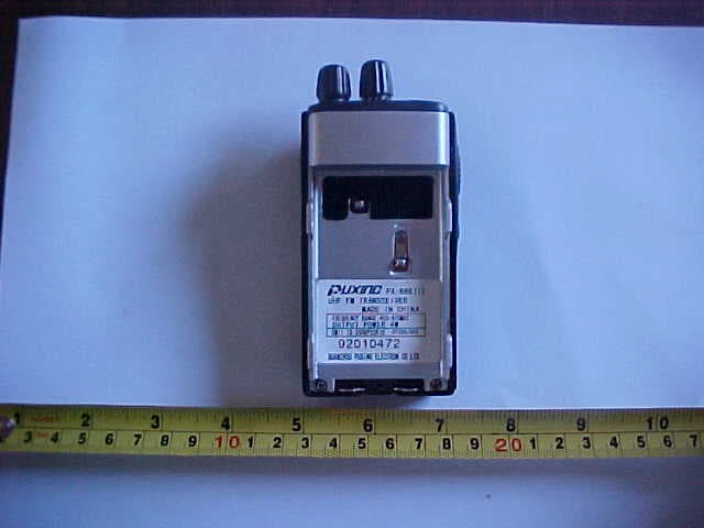
Q9FPX666
Nov 08, 2006Professional FM Transceiver
Equipment Class
TNF - Licensed Non-Broadcast Transmitter Held to Face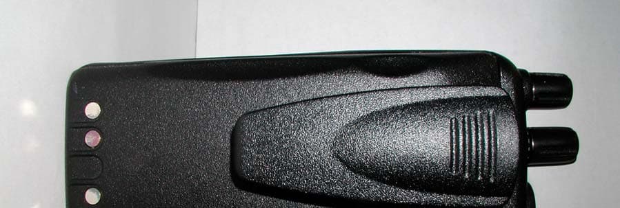
Q9FKY104L
Oct 26, 2004Low Band Portable Two-Way Radio
Equipment Class
TNF - Licensed Non-Broadcast Transmitter Held to Face