Q9ONOODLEBUDSWireless Bluetooth Earbuds
Triamp Technology., Ltd.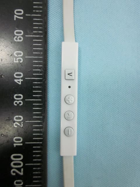
Click to zoom
Application Details
- Equipment Class
- DSS - Part 15 Spread Spectrum Transmitter
- Date of Grant
- Mar 16, 2015
- Application Purpose
- Original Equipment
- Date of Application
- Mar 16, 2015
- Equipment Note
- Wireless Bluetooth Earbuds
- Frequency Range
- 2402.00000000 - 2480.00000000
- Company
- Triamp Technology., Ltd.
- Country
- Taiwan
Documents & Files
Document Text
Text extracted from the exhibit documents filed with the FCC. Open a document above to read the original.
Users Manual
OVER-EAR FITTING 14 12 26 USE YOUR FINGER TO GENTLY INSERT THE EARBUDS IN YOUR EAR. TAKE OFF HEADPHONES, INSERT CORD INTO THE FINAL ROUNDED SLOTS, PUT HEADPHONES BACK ON, NOW YOU ARE READY TO GO! 24 01 YOU CHOOSE YOUR EAR TIPS FOR COMFORT AND STABILITY... NOW IT’S TIME TO EXPERIENCE PURE MUSIC PLEASURE. THIS IS THE OVER-EAR FITTING OPTION. IT IS NOT NECESSARY TO REMOVE THE EARBUD STABILIZERS TO ADJUST THEM FOR AN OVER-EAR FITTING. 16 18 20 22 THE OVER-EAR FITTING OPTION IS DESIGNED FOR PURE LISTENING PLEASURE. THE MICROPHONE AND CONTROLS ARE LOCATED BEHIND THE EAR IN THIS FITTING OPTION. WHILE OVER-EAR FITTING IS A GREAT WAY TO LISTEN TO MUSIC, SOME ADJUSTMENT IS REQUIRED TO FIT THE EARBUDS CORRECTLY. 04 CORD MANAGEMENT CLIPS INSERT CORD INTO THE 2 SLOTS IN EACH CLIP AS SHOWN. OVER-EAR MODE REQUIRES LESS CORD, SO BEFORE FITTING, INSTALL THE CORD MANAGEMENT CLIPS TO SECURE THE SLACK FOR A CUSTOMIZED FIT. SEE NEXT STEPS. THE EARBUD AND EAR TIP DESIGN IS INTENDED TO FIT COMFORTABLY IN THE EAR CANAL. IN COMBINATION WITH THE EARBUD STABILIZER, YOUR EARBUDS MAKE LISTENING TO MUSIC SHEER ECSTASY. INSTALL THE EAR STABILIZER OVER THE EARBUD AS SHOWN. TO ADJUST THE FIT, ROTATE THE STABILIZER ON THE EARBUD. R 03 EAR BUD ORIENTATION OVER LEFT EAR: Controller and MIC location L THE EAR TIP IS SPECIFICALLY DESIGNED FOR A SPECIFIC EAR ORIENTATION. FOR BEST RESULTS USE THE LEFT EARBUD IN THE LEFT EAR. 02 COMFORTABLY SECURED RL INSERT THE EARBUD IN YOUR EAR AND ADJUST AS THE EAR STABILIZER NEEDED FOR MAXIMUM COMFORT. IT IS BEST TO TEST EACH EAR TIP TO DETERMINE THE BEST FIT AND SOUND PERFORMANCE. MAKE AN “S” SHAPE WITH THE MIDDLE SECTION OF THE CORD. 06 Connected CONTROLS AND MIC ON LEFT SIDE 02 EARBUD ORIENTATION 04 EAR TIP ANGLE DESIGN FOLLOWS INWARD DIRECTION OF YOUR EAR CANAL FOR A SNUG FIT. LR SETTING UP AND FITTING 02 INDEX BASIC SETUP SETTING UP AND FITTING OVER-EAR FITTING USING THE EARBUDS ACCESSORIES CHARGING THE BATTERY PAIRING COMMANDS SPECIFICATION ...................................................................................02 ...............................................................................................14 ..................................................................................................... 31 .................................................................................... 31 .............................................................................................................. 33 ...................................................................................................... 37 ............................................................................................ 38 WARRANTY ............................................................................................ 39 THE EAR STABILIZERS CAN BE ADJUSTED FOR BEST FIT. POSITION THE EAR STABILIZER AS SHOWN AND GENTLY ADJUST OVER THE NOZZLE. 08 05 COMFORT AND SECURITY RL IN PLACE TO A MORE COMFORTABLE AND SECURE FIT. STABILIZER CONTROL ON Left EAR ROTATE THE STABILIZER SO IT FITS UNDERNEATH THE RIM OF THE EAR STEM. ONCE ADJUSTED, THE STABILIZER FITS UNDER THE EAR STEM AND 10 04 PROPER FITTING The best music performance is only achieved with the right ear to eartip seal. NEED TO PAIR? See page 33-37 to pair your earbuds. HOLD 4 SEC. TO PAIR “PAIRING” 06 ON ATTACH AN EAR TIP AND PAIR YOUR EARBUDS TO A BLUETOOTH ENABLED DEVICE. TRY EACH EAR TIP TO DETERMINE THE BEST FIT AND SOUND PERFORMANCE. ALTERNATING RED/BLUE USER GUIDE Wireless Bluetooth Earbuds 03 THE RIGHT SIZE FOR GREAT SOUND PERFORMANCE HEARING IS BELIEVING Great sound can only be believed with the right size eartip. Occassionally the eartips move out of place due to body movement resulting in a reduction in audio quality. The earbud stabilizers hold the earbuds in place to a more comfortable and secure fit. L M S THE CORD MANAGEMENT CLIPS SILICON EAR TIPSEAR STABILIZERWIRELESS BLUETOOTH EARBUDS 01 WHAT'S INSIDE THE STABILIZERS ARE ONLY AVAILABLE FOR THE TYPE OF EAR TIPS INDICATED IN THE ILLUSTRATION. ADD STABILITY AND COMFORT VOICE PROMPT: INSTALL THE EAR STABILIZER TO HOLD THE EARBUDS CREATES A COMFORTABLE SNUG FIT. 39 41 36 40 38 35 37 34 32 30 ACCESSORIES CHARGING 29 27 25 23 21 19 17 15 13 11 09 07 05 03 01 31 33 USING THE EARBUDS CONNECTED 05 HOLD 4 SEC TO PAIR AUDIBLE: When you hear “Power on”, continue pushing until you hear “PAIRING”. PAIRING MODE: ALTERNATING RED AND BLUE LEDS REGISTER YOUR DEVICE TO RECEIVE UPDATE INFORMATION http://www.noodlebuds.com GREAT MUSIC REQUIRES GOOD EARS Avoid prolonged periods of use and excessive audio levels. The use of earbuds around road traffic is not advisable. Wireless bluetooth earbuds Carrying case 3 eartips pairs (S,M,L) 1 ear stabilizer pair 2 cord management clips 1 USB cable 1 quick start quicle Before using your Bluetooth earbuds, make sure you fully charge them to extend the life of the battery. 1. To access the USB port (controller box), pull back the cover to expose the USB port. 2. Insert the USB cable into the port. The LED light starts red and turns blue once charging is complete. A full charging requires up to 1.5 hours. 3. To check earbuds’ battery status: Turn earbuds on. top volume up or down to trigger a status response. Note:When listening to music, tap Pause and wait for blue LED to flash rapidly. Tap volume up or down to trigger a status response. PAIRING TO YOUR PHONE / MUSIC DEVICE THE FIRST TIME 1. Press and hold the audio/call button for more than four seconds. The LED flashes an alternating red and blue indicating the pairing process is ongoing. 2. Turn on the Bluetooth on your phone/device and allow it to search for new devices. 3. Select the [NOODLEBUDS] to initiate pairing. If a password is necessary, enter 0000. After successfully pairing to your phone/device, an audible prompt “Headset connected” is heard. 4. If the pairing is not successful, power down the earbuds by pressing the the audio/call button for four seconds. Repeat the pairing process onc…
Text truncated - open the document above for the full version.
External Photos
ETC Report No. : 14-12-RBF-004-03 FCC ID: Q9ONOODLEBUDS Sheet 1 of 9 Sheets Rev. No 2.1 CONSTRUCTION PHOTOS OF EUT 1. 2. ETC Report No. : 14-12-RBF-004-03 FCC ID: Q9ONOODLEBUDS Sheet 2 of 9 Sheets Rev. No 2.1 CONSTRUCTION PHOTOS OF EUT 3. 4. ETC Report No. : 14-12-RBF-004-03 FCC ID: Q9ONOODLEBUDS Sheet 3 of 9 Sheets Rev. No 2.1 CONSTRUCTION PHOTOS OF EUT 5. 6. ETC Report No. : 14-12-RBF-004-03 FCC ID: Q9ONOODLEBUDS Sheet 4 of 9 Sheets Rev. No 2.1 CONSTRUCTION PHOTOS OF EUT 7. 8.
ID Label/Location Info
6 x 30 mm FCC ID: Q9ONOODLEBUDS
Internal Photos
ETC Report No. : 14-12-RBF-004-03 FCC ID: Q9ONOODLEBUDS Sheet 5 of 9 Sheets Rev. No 2.1 CONSTRUCTION PHOTOS OF EUT 9. 10. ETC Report No. : 14-12-RBF-004-03 FCC ID: Q9ONOODLEBUDS Sheet 6 of 9 Sheets Rev. No 2.1 CONSTRUCTION PHOTOS OF EUT 11. 12. ETC Report No. : 14-12-RBF-004-03 FCC ID: Q9ONOODLEBUDS Sheet 7 of 9 Sheets Rev. No 2.1 CONSTRUCTION PHOTOS OF EUT 13. 14. ETC Report No. : 14-12-RBF-004-03 FCC ID: Q9ONOODLEBUDS Sheet 8 of 9 Sheets Rev. No 2.1 CONSTRUCTION PHOTOS OF EUT 15. 16. ETC Report No. : 14-12-RBF-004-03 FCC ID: Q9ONOODLEBUDS Sheet 9 of 9 Sheets Rev. No 2.1 CONSTRUCTION PHOTOS OF EUT 17.
RF Exposure Info
Statement of Justification and Compliance for SAR Test Exclusion Product: Wireless Bluetooth Earbuds FCC ID: Q9 ONOODLEBUDS Manufacturer: Triamp Technology Ltd. Brand: ViseeO Model: NoodleBuds, NoodleBuds G2, NoodleBuds G3, NoodleBuds xxx According to FCC KDB 447498 D01 General RF Exposure Guidance v05 4.3.1. Standalone SAR test exclusion considerations 1) The 1-g and 10-g SAR test exclusion thresholds for 100 MHz to 6 GHz at test separation distances ≤ 50 mm are determined by: [(max. power of channel, including tune-up tolerance, mW)/(min. test separation distance, mm)] · [√f (GHz)] ≤ 3.0 for 1-g SAR and ≤ 7.5 for 10-g extremity SAR, 16 where f(GHz) is the RF channel transmit frequency in GHz Power and distance are rounded to the nearest mW and mm before calculation The result is rounded to one decimal place for comparison The test exclusions are applicable only when the minimum test separation distance is ≤ 50 mm and for transmission frequencies between 100 MHz and 6 GHz. When the minimum test separation distance is < 5 mm, a distance of 5 mm is applied to determine SAR test exclusion. For the present device, the declared output power is 4dBm with +/- 0.5dB tolerance. So, max. power of channel, including tune-up tolerance = 2.818 mW (4.5dBm) min. test separation distance = 5 mm f(GHz) = 2.480 [(max. power of channel, including tune-up tolerance, mW)/(min. test separation distance, mm)] · [√f(GHz)] = (2.818 / 5) · (√2.480) = 0.9 ≤ 3.0 Hence the SAR Exclusion Threshold condition is satisfied and the SAR evaluation for general population exposure conditions is not required.
Test Report
Rev. No 1.0 FCC Part 15 EMI TEST REPORT of E.U.T. : Wireless Bluetooth Earbuds Model : NoodleBuds FCC ID : Q9ONOODLEBUDS for APPLICANT : TRIAMP TECHNOLOGY LTD. ADDRESS : 3F No. 2 Alley 16 Lane 235 Bao Chiao Road, Hsin-Tien District, New Taipei City, Taiwan Test Performed by ELECTRONICS TESTING CENTER, TAIWAN NO. 34. LIN 5, DINGFU VIL., LINKOU DIST., NEW TAIPEI CITY, TAIWAN, 24442, R.O.C. Tel:(02)26023052 Fax:(02)26010910 http://www.etc.org.tw ; e-mail : [email protected] Report Number : 14-12-RBF-004-03 ETC Report No. : 14-12-RBF-004-03 FCC ID: Q9ONOODLEBUDS Rev. No 1.0 TEST REPORT CERTIFICATION Applicant : Triamp Technology Ltd. 3F No. 2 Alley 16 Lane 235 Bao Chiao Road, Hsin-Tien District, New Taipei City, Taiwan Manufacture : Triamp Technology Ltd. 3F No. 2 Alley 16 Lane 235 Bao Chiao Road, Hsin-Tien District, New Taipei City, Taiwan Description of Device : a) Type of EUT : Wireless Bluetooth Earbuds b) Trade Name : ViseeO c) Model No. : NoodleBuds d) Series Model No. : NoodleBuds G2, NoodleBuds G3, NoodleBuds xxx e) Power Supply : Power from PC Regulation Applied : FCC Rules and Regulations Part 15 Subpart C I HEREBY CERTIFY THAT: The data shown in this report were made in accordance with the procedures given in ANSI C63.4, and the energy emitted by the device was founded to be within the limits applicable. I assume full responsibility for accuracy and completeness of these data. Note: 1. The result of the testing report relate only to the item tested. 2. The testing report shall not be reproduced expect in full, without the written approval of ETC. Summary of Tests Test Results Radiated Emission Pass Conducted Emission Pass Hopping Channel Separation Pass Number of Hopping frequencies used Pass Hopping Channel Bandwidth Pass Dwell Time of each frequency Pass Output Power Requirement Pass 100 kHz Bandwidth of Frequency Band Edges Requirement Pass Out-of-Band Conducted Emission Requirement Pass ETC Report No. : 14-12-RBF-004-03 FCC ID: Q9ONOODLEBUDS Rev. No 1.0 Date Test Item Received : Dec. 01, 2014 Date Test Campaign Completed : Dec. 09, 2014 Date of Issue : Dec. 25, 2014 Test Engineer : ( Jiapeng Chen , Engineer ) Approve & Authorized : S. S. Liou, Section Manager EMC Dept. II of ELECTRONICS TESTING CENTER, TAIWAN ETC Report No. : 14-12-RBF-004-03 FCC ID: Q9ONOODLEBUDS Rev. No 1.0 Table of Contents Page 1 GENERAL INFORMATION ....................................................................................................... 1 1.1 Product Description...................................................................................................................... 1 1.2 Test Methodology ........................................................................................................................ 1 1.3 Test Facility.................................................................................................................................. 1 2 PROVISIONS APPLICABLE...................................................................................................... 2 2.1 Definition ..................................................................................................................................... 2 2.2 Requirement for Compliance ....................................................................................................... 3 2.3 Restricted Bands of Operation ..................................................................................................... 5 2.4 Labeling Requirement .................................................................................................................. 6 2.5 User Information .......................................................................................................................... 6 3 SYSTEM TEST CONFIGURATION .......................................................................................... 7 3.1 Justification .................................................................................................................................. 7 3.2 Devices for Tested System........................................................................................................... 7 4 RADIATED EMISSION MEASUREMENT .............................................................................. 8 4.1 Applicable Standard ..................................................................................................................... 8 4.2 Measurement Procedure............................................................................................................... 8 4.3 Measuring Instrument ................................................................................................................ 10 4.4 Radiated Emission Data ............................................................................................................. 11 4.5 Field Strength Calculation.......................................................................................................... 21 4.6 Photos of Radiation Measuring Setup........................................................................................22 5 CONDUCTED EMISSION MEASUREMENT ........................................................................ 23 5.1 Standard Applicable ................................................................................................................... 23 5.2 Measurement Procedure............................................................................................................. 23 5.3 Conducted Emission Data .......................................................................................................... 24 5.4 Result Data Calculation.............................................................................................................. 26 5.5 Conducted Measurement Equipment ......................................................................................... 26 5.6 Photos of Conduction Measuring Setup................................................…
Text truncated - open the document above for the full version.
Test Setup Photos
ETC Report No. : 14-12-RBF-004-03 FCC ID: Q9ONOODLEBUDS Sheet 22 of 99 Sheets Rev. No 2.1 4.6 Photos of Radiation Measuring Setup ETC Report No. : 14-12-RBF-004-03 FCC ID: Q9ONOODLEBUDS Sheet 27 of 99 Sheets Rev. No 2.1 5.6 Photos of Conduction Measuring Setup
Contact Information
Applicant
Vincent Shen(General manager)
Test Firm
Taiwan Testing and Certification CenterAnderson Ku
Technical Specifications
| # | Rule Parts | Frequency Range | Power Output |
|---|---|---|---|
| 1 | 15C | 2.40 GHz - 2.48 GHz | 1.00 mW |
Other Applications from Triamp Technology., Ltd.
Q9OWMA1K2K3K
Mar 20, 2013Wireless Bluetooth Music Interface Adaptor
Equipment Class
DSS - Part 15 Spread Spectrum Transmitter
Q9OMBU-1000
Feb 24, 2008Bluetooth Upgrade Kit
Equipment Class
DSS - Part 15 Spread Spectrum Transmitter
Q9OMBU-2000
Feb 24, 2008Bluetooth Upgrade Kit
Equipment Class
DSS - Part 15 Spread Spectrum Transmitter