QAOWSZEP003Engergy Saving Lamp-Lighting Device
Shanghai East Pearl Lighting Co., Ltd.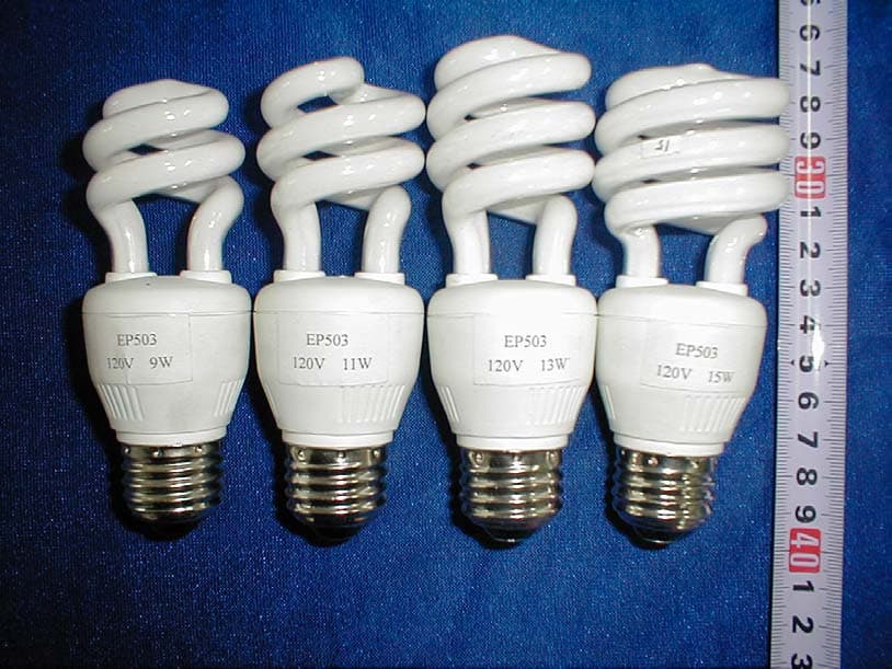
Click to zoom
Application Details
- Equipment Class
- 8CC - Part 18 Consumer Device
- Date of Grant
- Apr 22, 2002
- Application Purpose
- Original Equipment
- Date of Application
- Apr 22, 2002
- Equipment Note
- Engergy Saving Lamp-Lighting Device
- Frequency Range
- 0.04000000 - 0.05000000
- Country
- China
Documents & Files
Document Text
Text extracted from the exhibit documents filed with the FCC. Open a document above to read the original.
Users Manual
User manual Compared with an incandescence lamp, a series of compact energy saving lamp have a lot of merits. For instance: battery saving 80%, the quantity of heat less than 80% and without noise and flicker etc, so it is widely used by hotel, school, shop and family etc. under this conditions, this style of lamp is popular by much more customer, and it is named “ Green illumination-new lamp source” title. Notice ! Without special mark, it can’t be used as dimmer. In other words, the lamp can’t become bright or dim. ! Damp fossa, chemical history, and the floor with water or rain are stopped to use. ! In avoid to explode and fire, it can’t be used to defend blast, and the site where gas is easy to reach saturation isn’t used. ! While tearing it down or setup, your hands can’t straight grasp lamp-tube and lamp-chimney, and should hold the plastic enclosure to handle. ! When repairing, No special clerk can’t tear it down to repair. If needing repairing, should reach to the appointed site, or repaired by special people. Shanghai East Pearl Lighting Co., Ltd. Block Diagram Circuit expla nation: A 120VAC/60Hz power source pass L1, C1, R1, then process to control the harmonic which the line produce feedback to electrical net, and have the harmonic reach (or accord with) requirement. Next process to rectify by D1, D2, C2, C3, and supply a stable DC power source to the line, next pass V1, V2 and the near component, make it form the high-frequency switch circuit, and have frequency changi ng at 41~43KHz range, fi nall y output by L4, C6, C7, and provi de to a loaded Input Circuit Ballast Circuit Vibration Circuit Output Circuit Loader lamp-tube, have it working.
External Photos
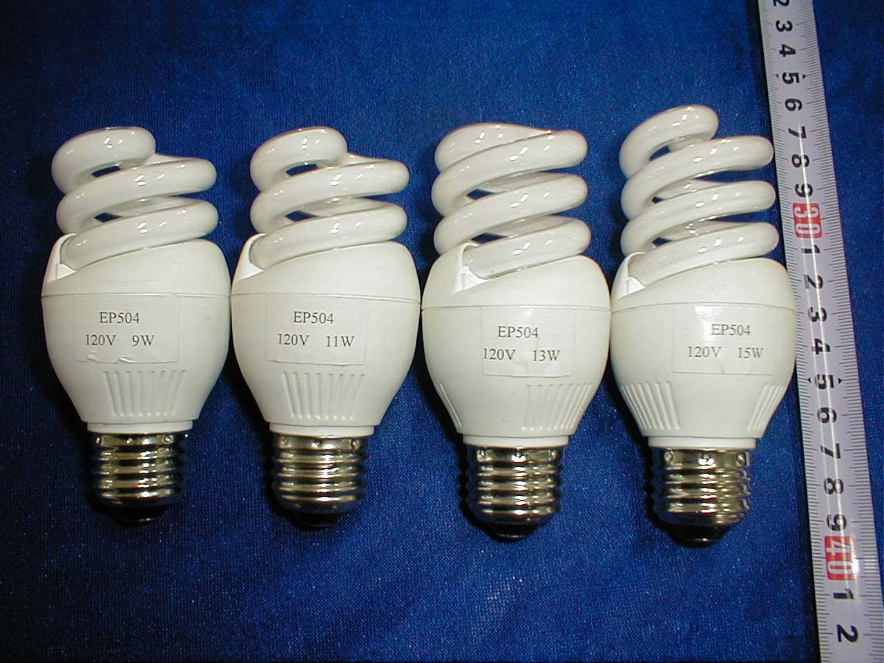
QAOWSZEP003 Model: EP104 Photograph of EUT Overall View Model: EP201 Photograph of EUT Overall View Model: EP302 Photograph of EUT Overall View Model: EP503 Photograph of EUT Overall View
ID Label/Location Info
FCC PRODUCT LABELING 5.1 Proposed FCC Label Format Specifications : Text is Black or white in color and is left justified. Labels are printed in indelible ink on permanent adhesive backing or silk-screened onto the EUT or shall be affixed at a conspicuous location on the EUT. Proposed Label Location on EUT FCC Authorization FCC authorization was presented in Appendix E of this report as reference. Trade Name Model Number This device complies with Part 18 of the FCC Rules EUT Overall View FCC Mark Location Trade Name Model Num ber This device complies with Part 18 of the FCC Rules
Internal Photos
QAOWSZEP003 Model: EP104 Photograph of EUT Uncovered View Model: EP201 Photograph of EUT Uncovered View Model: EP302 Photograph of EUT Uncovered View Model: EP503 Photograph of EUT Uncovered View
Test Report
Note: This report may not be duplicated without prior written consent of Bay Area Compliance Laboratory Corporation. This report must not be used by the client to claim product endorsement by NVLAP or any agency of the U.S. Government. FCC PART 18 CONSUMER EQUIPMENT EMI MEASUREMENT AND TEST REPORT FOR SHANGHAI EAST PEARL LIGHTING CO., LTD. No. 1399 Yongtai Road, Pudong New District, Shanghai 200124, P. R. China MODEL: QAOWSZEP003 March 23, 2002 This Report Concerns: Original Report Equipment Type: Energy saving lamp-lighting device Test Engineer: Peter Liao Test Date: March 21, 2002 Certified By: John Y. Chan – Engineering Manager Prepared By: Bay Area Compliance Laboratory Corporation 230 Commercial Street Sunnyvale, CA 94085 Tel: (408) 732 9162 Fax: (408) 732 9164 SHANGHAI EAST PEARL LIGHTING CO., LTD. QAOWSZEP003 Report # RSH0203013 FCC Part 18 DoC Report Page 2 of 24 TABLE OF CONTENTS 1 - GENERAL INFORMATION..................................................................................................................................3 1.1 PRODUCT DESCRIPTION FOR EQUIPMENT UNDER TEST (EUT) ..............................................................................3 1.2 OBJECTIVE.............................................................................................................................................................3 1.3 RELATED SUBMITTAL(S)/GRANT(S).......................................................................................................................3 1.4 TEST METHODOLOGY............................................................................................................................................3 1.5 TEST FACILITY.......................................................................................................................................................3 1.6 TEST EQUIPMENT LIST...........................................................................................................................................4 1.7 EQUIPMENT UNDER TEST (EUT) ...........................................................................................................................4 1.8 LOCAL SUPPORT EQUIPMENT LISTS AND DETAILS.................................................................................................5 2 - SYSTEM TEST CONFIGURATION.....................................................................................................................6 2.1 JUSTIFICATION.......................................................................................................................................................6 2.2 EUT EXERCISE PROGRAM.....................................................................................................................................6 2.3 SCHEMATICS/BLOCK DIAGRAM.............................................................................................................................6 2.4 EQUIPMENT MODIFICATIONS.................................................................................................................................6 2.5 CONFIGURATION OF TEST SYSTEM.........................................................................................................................7 2.6 TEST SETUP BLOCK DIAGRAM...............................................................................................................................8 3 - CONDUCTED EMISSIONS TEST ........................................................................................................................9 3.1 MEASUREMENT UNCERTAINTY..............................................................................................................................9 3.2 EUT SETUP............................................................................................................................................................9 3.3 SPECTRUM ANALYZER...........................................................................................................................................9 3.4 TEST PROCEDURE................................................................................................................................................10 3.5 SUMMARY OF TEST RESULTS...............................................................................................................................10 3.6 CONDUCTED EMISSIONS TEST DATA (0.45-30MHZ). ..........................................................................................10 3.7 CONDUCTED EMISSIONS TEST PHOTOS................................................................................................................14 4 - RADIATED EMISSIONS TEST ..........................................................................................................................15 4.1 MEASUREMENT UNCERTAINTY............................................................................................................................15 4.2 EUT SETUP..........................................................................................................................................................15 4.3 SPECTRUM ANALYZER SETUP..............................................................................................................................15 4.4 TEST PROCEDURE................................................................................................................................................16 4.5 CORRECTED AMPLITUDE & MARGIN CALCULATION...........................................................................................16 4.6 SUMMARY OF TEST RESULTS...............................................................................................................................16 4.7 RADIATED EMISSIONS TEST RESULT DATA, FULLY CONFIGURED, 3 METER. ......................................................16 4.8 RADIATED EMISSIONS TEST PHOTOS................................................................................…
Text truncated - open the document above for the full version.
Test Setup Photos
QAOWSZEP003 Model: EP104 Photograph of Conducted Emission Test Setup Front View (EP104-9W) Photograph of Conducted Emission Test Setup Side View (EP104-9W) Photograph of Radiated Emission Test Setup View (EP104-9W) Model: EP201 Photograph of Conducted Emission Test Setup Front View (EP201-13W) Photograph of Conducted Emission Test Setup Side View (EP201-13W) Photograph of Radiated Emission Test Setup View (EP201-13W) Model: EP302 Photograph of Conducted Emission Test Setup Front View (EP302-15W) Photograph of Conducted Emission Test Setup Side View (EP302-15W) Photograph of Radiated Emission Test Setup View (EP302-15W) Model: EP503 Photograph of Conducted Emission Test Setup Front View (EP503-15W) Photograph of Conducted Emission Test Setup Side View (EP503-15W) Photograph of Radiated Emission Test Setup View (EP503-15W)
Contact Information
Applicant
Albert Wang(Vice Manager)
Test Firm
Bay Area Compliance LaboratoryJohn Chan
Technical Specifications
| # | Rule Parts | Frequency Range | Power Output |
|---|---|---|---|
| 1 | 18 | 0.04 MHz - 0.05 MHz | - |
Other Applications from Shanghai East Pearl Lighting Co., Ltd.
QAOWSZEP002
Apr 22, 2002Energy Saving Lamp-Lighting Device
Equipment Class
8CC - Part 18 Consumer Device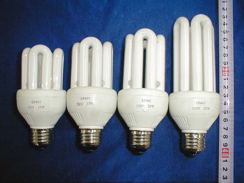
QAOWSZEP001
Apr 22, 2002Energy Saving Lamp-Lighting Device
Equipment Class
8CC - Part 18 Consumer Device