QAZREALUSB-TVUSB TV Receiver
DiVACESS Inc.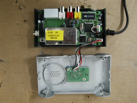
Click to zoom
Application Details
- Equipment Class
- JBP - Part 15 Class B Computing Device Peripheral
- Date of Grant
- May 08, 2002
- Application Purpose
- Original Equipment
- Date of Application
- May 08, 2002
- Equipment Note
- USB TV Receiver
- Company
- DiVACESS Inc.
- Country
- South Korea
Documents & Files
Document Text
Text extracted from the exhibit documents filed with the FCC. Open a document above to read the original.
Users Manual
Report Number: DAC02 Appendix D - EUT User’s Manual USER’S MANUAL. Contents Starting of USB TV Main Feature Main Functions Product Specification User’s Interface Included goods in package Setting of Hardware Setting of Program Introduction of Real TV Player Support FCC NOTICE This equipment has been tested and found to comply with the limits for Class B digital device, pursuant to part 15 of the FCC Rules. These limits are designed to provide reasonable protection against harmful interference in a residential installation. This equipment generates, uses and can radiate radio frequency energy and, if not installed and used in accordance with the instructions, may cause harmful interference to radio communication. However, there is no guarantee that interference will not occur in a particular installation. If this equipment does cause harmful interference to radio or television reception, which can be determined by turning the equipment off and on, the user is encouraged to try to correct the interference by one or more of the following measures: - Reorient or relocate the receiving antenna. - Increase the separation between the equipment and receiver. - Connect the equipment into an outlet on a circuit difference from that to which the receiver is connected. - Consult the dealer of an experienced radio/TV technician for help. Note : This unit was tested with shielded cables on the peripheral devices. Shielded cables must be used with the unit to insure compliance. Note : The manufacturer is not responsible for any radio or TV interference caused by unauthorized modifications to this equipment. Such modifications could void the user’s authority to operate the equipment. Starting THIS DEVICE COMPLIES WITH PART 15 OF THE FCC RULES. OPERATION IS SUBJECT TO THE SOLLOWING TWO CONDITIONS: (1) THIS DEVICE MAY NOT CAUSE HARMFUL INTERFERENCE, AND (2) THIS DEVICE MUST ACCEPT ANY INTERFERENCE RECEIVED, INCLUDING INTERFERENCE THAT MAY CAUSE UNDERSIRED OPERATION. Real USB-TV is supported USB port and new generation of video capture material able to watching TV/Video & capture video. Real USB-TV can display video & audio from VCR, LDP, Cam-corder or etc on computer moniter and capture this screen to Digital data, so it is not only for watching TV, but the best solution of your computer. Main Features 1) Excellent System Compatibility & Perfect Plug & Play (PnP) Support 2) Portable TV with Self Antenna, Audio Function 3) Improved Video quality with the latest technology 4) Recording & Streaming System (Supporting MPEG-4 way of WMT perfectly) 5) Remote conditioner function (Option) 6) Compact Design Main Functions 1) TV Receiver supports TV/Cable-TV, Supply Internal Antenna & External Cable, Automatic Channel setting & Memory. 2) External Video Input You can watch and enjoy the Video or Games on the screen of USB TV by connection of external video equipment like cam-corder or game machine. Specially it supplies not only normal Video signal but also Super-video output, so if it is connected to cam-corder with S-Video output, the screen will be more clear. 3) 640*480 Full Screen Video Play 4 times of multi-memory comparing with normal USB capture equipment & Full screen of 640*480 with improved technology 4) Snapshot Capture, Recording of motion screen Max.640*480 size of snapshot capture and recording of motion picture. -In case of Recording Motion picture of MPEG-4(WMV) & Quality of MPEG-1(Video CD), 1.5G hard disk can record more than 10 hours (Recommended capacity for 320*240 30fps : P-III 500MHz / RAM 128MB) 5) Motion picture Streaming Broad-cast The motion picture on PC thru Real USB-TV can be seen in the other place connected by network or internet 6) Caption function 7) Remote-control (Option) Specification Item Classifications Contents PC I/F USB V1.1 Tuner Broadcasting System Channels Antenna NTSC-M VHS/UHF/CA-TV Built-in, External Antenna Standard Resolution Frame Rate NTSC/PAL CCIR601, CIF 30fps Max Video Input Built-in Tuner External Video, S-Video Video Control Brightness/Contrast Saturation/Hue Input Built-in Tuner External Audio Audio Output USB Audio Size 125*75*30(mm) Dimension Weight User’s interface - Minimum needs for System ♣ PC : Celleron 300Mhz / RAM 64MB ♣ OS : Over Windows 98 (Over DirectX8.0 / MediaPlayer 7.0 ) ♣ HDD : Space of over 20MB - Recommended needs for record Video of 30frm ♣ Over Pentium -733Mhz / RAM 128MB Included goods in package User’s manual CD_RAM for setting Real TV receiver Line-out cable Setting Please set if your window do not have followings. l DirectX 8.0 It is included in setting CD, but we recommend to download new version from web site of microsoft. l Window Media Incorder 7.0 It is included in setting CD, but we recommend to download new version from web site of microsoft. Warning l If you set DirectX 8.0, it rarly can be incompatible with VGA or Sound card. If it occurs, please solve the problems with each relavent company. l VIA Board can be occurred problem in Win 98, in this case, please set USB VIA PATCH additionally. l Other problems may written in web page in Microsoft or Real TV of FAQ Part. Setting of Hardware 1. If you connect Real TV to your PC thru USB Port, you can see Composite USB Device as following or USB Serching Box, please press Next. 2. After select the first one, please press Next 3. Insert CD-ROM after select (L) and then, Please press [Search(R)] and select the Drive included CD-ROM and select the directory as following, and then please press Next. 4. Please press Next, if you can see the following box. 5. Press Finish and then setting of Nogatech USB TV!Pro(NTSC+) is completed. 6. Next is the process of setting Nogatech USB TV! Pro Audio (N+). Please press Next. 7. After select the first one, please press Next. 8. Please select D:\Driver in (L) and then press Next. 9. Please press Next, if you can see the following box. 10. Press Finish and then setting of Nogatech USB TV!Pro Audio(N+) is completed. 11. Please select Device Manage…
Text truncated - open the document above for the full version.
Block Diagram
Report Number: DAC02-K0184 Page 16 of 21 Appendix B - Block Diagram/Schematics VIDEO SAA7113H Y[0~7] I2C Ã MAIN NT1004, NT1005 AUDIO DAT IN POWER 3.3V 5V REMOCON RECEIVER MODULE OUT AUDIO MULTIPLEXER 4052 AUDIO CODEC MSM7716GS-K TV CV 12C TUNER TCPN9081DA10B AUD IN, OUT
External Photos
Report Number: DAC02-K0184 Page 19 of 21 Appendix D - EUT Photographs Report Number: DAC02-K0184 Page 20 of 21 Appendix D - EUT Photographs
ID Label/Location Info
Report Number: DAC02-K0184 Page 15 of 21 Appendix A - Sample Label Labeling Requirements per section 2.925&15.19 The label shown shall be permanently affixed at a conspicuous location on the device and be readily visible to the user at the time of purchase. Label Location : Bottom [Photograph of the physical location of the label ] DiVACESS INC. PRODUCT : USB TV RECEIVER MODEL : REAL USB-TV SERIAL NO : 100007 FCCID : QAZREALUSB-TV This device complies with Part 15 of the FCC Rules. Operation is subject to following two conditions: (1)this device may not cause harmful interference, and (2)this device must accept any interference received , including interference that may cause undesired operation. MADE IN KOREA
Internal Photos
Report Number: DAC02-K0184 Part Photographs of EUT – MAIN BOARD Report Number: DAC02-K0184 Part Photographs of EUT – MAIN BOARD
Test Report
Report Number: DAC02-K0184 Page 1 of 21 DASTEK EMC Lab 204, Chuge-Ri, Yangji-Myeon, Yongin -Shi, Kyunggi-Do, Korea Tel : 82-31-335-9341 Fax : 82-31-335-9343 Verificate of Compliance APPLICANT : DiVACESS Inc. EUT Type : USB TV RECEIVER Model Name : Real USB-TV Serial No : 100007 Manufacturer Name : DiVACESS Inc. Address & Country : 10 th , Happy World B/D., 917-6, Mok 1-dong, Yangcheon-gu, Seoul, 158-721, Korea Rule Part(s): : FCC 15 Subpart B Equipment Class : Class B This device has been shown to be capable of compliance with the applicable technical standard as indicated in the measurement report and was tested in accordance with the measurement procedures specified in ANSI C63.4-1992 with the following remarks (Note codes): (#37) I attest to the accuracy of data and all measurements reported herein were performed by me or were made under my supervision and are correct to the best of my knowledge and belief. I assume full responsibility for the completeness of these measurements and vouch for the qualifications of all persons taking them. Report No: DAC02-K0184 Issued Date : March 16, 2002 In-Young, Chung. Jun-Ho, Choi. Manager EMC Dept Test Engineer Report Number: DAC02-K0184 Page 2 of 21 Table of Contents Scope 3 Introduction (Site Description) 4 Product Information 5 Description of Test (Radiated & Conducted) 6-7 List of Support Equipment 8 Test Result(Radiated & Conducted) 9-10 Test Data (Radiated & Conducted) 11-12 Sample Calculations 13 List of Test Equipment 14 Appendix A - Labeling Requirements 15 Appendix B - Block Diagram / Schematics 16 Appendix C - Photographs of Test Set-up (Line Conducted and Radiated Test Pictures) 17-18 Appendix D - EUT Photographs 19-20 Appendix E – User’s Manual 21 Report Number: DAC02-K0184 Page 3 of 21 Scope Measurement and determination of electromagnetic emissions (EMI) of radio frequency devices including intentional and/or unintentional radiators for compliance with the technical rules and regulations of the Federal Communications Commission. FCC ID: : - Class: : Class B EUT Type : USB TV RECEIVER Model Name : Real USB-TV Trade Name : DiVACESS Inc.. Rule Part(s) : FCC Part 15 Subpart B Test Procedure : ANSI C-63.4 (1992) Date of Test(s) : March 16, 2002 Place of Tests : Dastek EMC Lab, in Korea. Test Report No : DAC02-K0184 Company Name : DiVACESS Inc. 10 th , Happy World B/D., 917-6, Mok 1-dong, Yangcheon-gu, Seoul, 158-721, Korea Report Number: DAC02-K0184 Page 4 of 21 Introduction These measurement tests were conducted at Dastek EMC Laboratory facility in Korea. The site address is 204 Chege-Ri, Yangji-Myeon, Yongin-City, Kunggi-Do, Korea. Dastek EMC Laboratory is a company that has started the July of 1981, for manufacturing of EMI noise filters and EMI Test and diverging service. The area of test site is located at 54 Kilometers (33miles) southeast from seoul International Airport, 42 Kilometers (26miles) south-southeast from central seoul where ambient radio signal conditions are quiet and a favorable area to measure the radio frequency interference on open field test site for the computing devices manufacturers. The detailed description of the measurement facility was found to be in compliance with the requirements of section 2.948 according to ANSI C63.4 on November 02, 2000(Registration Number:90547). Report Number: DAC02-K0184 Page 5 of 21 Product Information Equipment Description The Equipment under Test (EUT) is the USB TV RECEIVER of DiVACESS Inc. Model Name: Real USB-TV Serial Number : 100007 1. Specification See the manual Report Number: DAC02-K0184 Page 6 of 21 Description of Tests Conducted Emissions The line conducted facility is located inside a 4.6(m)x6.5(m)x2.5(m) shielded room. A wooden table 80cm high is located on one side of the shielded room; desktop EUTs are placed on top of this table. The rear of the EUT is placed a minimum of 40cm from the shielded room wall. The side of the EUT is 1m from the LISN, which is bonded to the shielded room wall Via a 1-foot wide bonding strap. The LISN is isolated from the other filtered power via an additional filter to ensure that RFI from the auxiliary instrumentation (scopes, etc.) does not influence the readings. The excess power cord from the EUT is folded back and forth to form a 30-40cm non-inductive bundle. All interconnecting cables more than 1 meter were shortened by non-inductive bundling (serpentine fashion) to a 1 meter length. Sufficient time for the EUT, support equipment, and test equipment was allowed in Order for them to warm up to their normal operating condition. The RF output of the LISN was connected to the spectrum analyzer to determine the frequency producing the maximum EMI from the EUT. The spectrum was scanned from 450KHz to 30MHz with 20 msec sweep time. The frequency producing the maximum level was reexamined using Quasi-Peak adapter. The detector function was set to CISPR quasi-peak mode. The bandwidth of the receiver was set to 9KHz. The EUT, support equipment, and interconnecting cables were arranged and manip- ulated to maximize each EMI emission. Each emission was maximized by: switching power lines, varying the mode of operation or resolution, clock or data exchange speed, scrolling H pattern to the EUT and/or support equipment, and powering the monitor from the floor mounted outlet box and the computer aux AC outlet, if applicable; whichever determined the worst-case emission. Photographs of the worst-case emission can be seen in Appendix C. Report Number: DAC02-K0184 Page 7 of 21 Radiated Emissions Preliminary measurements were made indoors at 1 meter using broadband antennas, broadband amplifier, and spectrum analyzer to determine the frequency producing the maximum EMI. Appropriate precaution was taken to ensure that all EMI from the EUT were maximized and investigated. The system configurations, clock speed, mode of operation or video resolution, turntable azimuth with respect to the antenna were noted for each Frequency found. The spectrum was s…
Text truncated - open the document above for the full version.
Test Setup Photos
Report Number: DAC02-K0184 Page 19 of 21 Appendix C - Test Photographs These Conducted Test Pictures shows the worst-case configuration and cable placement. [Conducted Emission Test Picture] Report Number: DAC02-K0184 Page 19 of 21 These Radiated Test Pictures shows the worst-case configuration and cable placement. [Radiated Emission Test Picture]
Contact Information
Applicant
In-Ho Song(Engineer)
Test Firm
Dastek Co., Ltd.S. Hwang
Technical Specifications
| # | Rule Parts | Frequency Range | Power Output |
|---|---|---|---|
| 1 | 15B | - | - |
Other Applications from DiVACESS Inc.
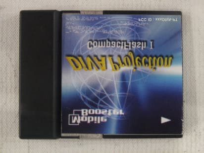
QAZDIVA-PT
Jun 23, 2002Projection Module for PDA
Equipment Class
JBP - Part 15 Class B Computing Device Peripheral